
Create successful ePaper yourself
Turn your PDF publications into a flip-book with our unique Google optimized e-Paper software.
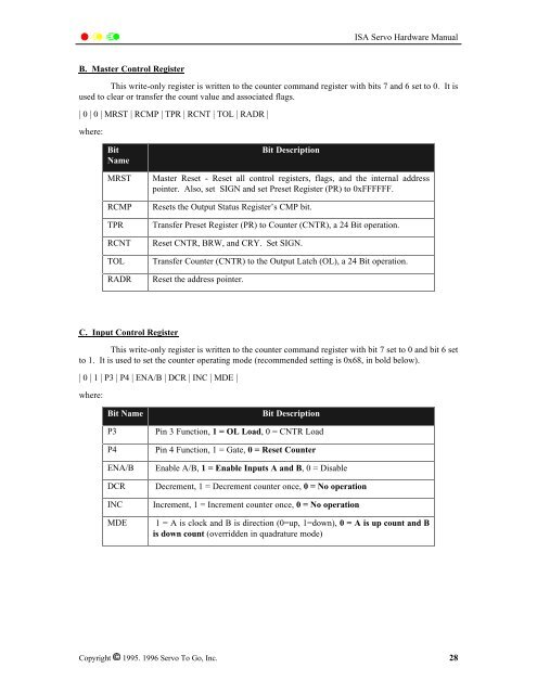
<strong>ISA</strong> <strong>Servo</strong> <strong>Hardware</strong> <strong>Manual</strong>B. Master Control RegisterThis write-only register is written to the counter command register with bits 7 and 6 set to 0. It isused to clear or transfer the count value and associated flags.| 0 | 0 | MRST | RCMP | TPR | RCNT | TOL | RADR |where:BitNameMRSTRCMPTPRRCNTTOLRADRBit DescriptionMaster Reset - Reset all control registers, flags, and the internal addresspointer. Also, set SIGN and set Preset Register (PR) to 0xFFFFFF.Resets the Output Status Register’s CMP bit.Transfer Preset Register (PR) to Counter (CNTR), a 24 Bit operation.Reset CNTR, BRW, and CRY. Set SIGN.Transfer Counter (CNTR) to the Output Latch (OL), a 24 Bit operation.Reset the address pointer.C. Input Control RegisterThis write-only register is written to the counter command register with bit 7 set to 0 and bit 6 setto 1. It is used to set the counter operating mode (recommended setting is 0x68, in bold below).| 0 | 1 | P3 | P4 | ENA/B | DCR | INC | MDE |where:Bit NameP3P4ENA/BDCRINCMDEBit DescriptionPin 3 Function, 1 = OL Load, 0 = CNTR LoadPin 4 Function, 1 = Gate, 0 = Reset CounterEnable A/B, 1 = Enable Inputs A and B, 0 = DisableDecrement, 1 = Decrement counter once, 0 = No operationIncrement, 1 = Increment counter once, 0 = No operation1 = A is clock and B is direction (0=up, 1=down), 0 = A is up count and Bis down count (overridden in quadrature mode)Copyright 1995. 1996 <strong>Servo</strong> To Go, Inc. 28