
Create successful ePaper yourself
Turn your PDF publications into a flip-book with our unique Google optimized e-Paper software.
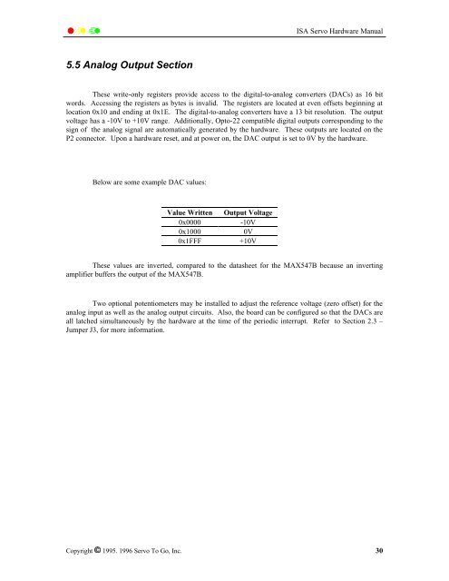
<strong>ISA</strong> <strong>Servo</strong> <strong>Hardware</strong> <strong>Manual</strong>5.5 Analog Output SectionThese write-only registers provide access to the digital-to-analog converters (DACs) as 16 bitwords. Accessing the registers as bytes is invalid. The registers are located at even offsets beginning atlocation 0x10 and ending at 0x1E. The digital-to-analog converters have a 13 bit resolution. The outputvoltage has a -10V to +10V range. Additionally, Opto-22 compatible digital outputs corresponding to thesign of the analog signal are automatically generated by the hardware. These outputs are located on theP2 connector. Upon a hardware reset, and at power on, the DAC output is set to 0V by the hardware.Below are some example DAC values:Value Written Output Voltage0x0000 -10V0x10000V0x1FFF +10VThese values are inverted, compared to the datasheet for the MAX547B because an invertingamplifier buffers the output of the MAX547B.Two optional potentiometers may be installed to adjust the reference voltage (zero offset) for theanalog input as well as the analog output circuits. Also, the board can be configured so that the DACs areall latched simultaneously by the hardware at the time of the periodic interrupt. Refer to Section 2.3 –Jumper J3, for more information.Copyright 1995. 1996 <strong>Servo</strong> To Go, Inc. 30