
You also want an ePaper? Increase the reach of your titles
YUMPU automatically turns print PDFs into web optimized ePapers that Google loves.
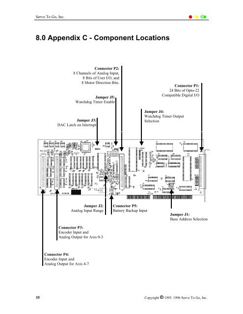
<strong>Servo</strong> To Go, Inc.8.0 Appendix C - Component LocationsConnector P2:8 Channels of Analog Input,8 Bits of User I/O, and8 Motor Direction Bits.Jumper J5:Watchdog Timer EnableJumper J3:DAC Latch on InterruptConnector P1:24 Bits of Opto-22Compatible Digital I/OJumper J4:Watchdog Timer OutputSelectionJumper J2:Analog Input RangeConnector P3:Encoder Input andAnalog Output for Axis 0-3Connector P5:Battery Backup InputJumper J1:Base Address SelectionConnector P4:Encoder Input andAnalog Output for Axis 4-735 Copyright 1995. 1996 <strong>Servo</strong> To Go, Inc.