
Create successful ePaper yourself
Turn your PDF publications into a flip-book with our unique Google optimized e-Paper software.
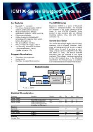
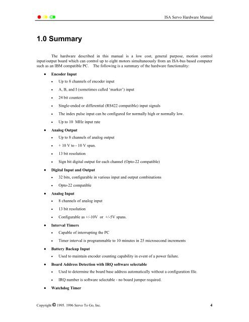
<strong>ISA</strong> <strong>Servo</strong> <strong>Hardware</strong> <strong>Manual</strong>1.0 SummaryThe hardware described in this manual is a low cost, general purpose, motion controlinput/output board which can control up to eight motors simultaneously from an <strong>ISA</strong>-bus based computersuch as an IBM compatible PC. The following is a summary of the hardware functionality:• Encoder Input• Up to 8 channels of encoder input• A, B, and I (sometimes called ‘marker’) input• 24 bit counters• Single-ended or differential (RS422 compatible) input signals• The index pulse input can be configured for normally high or normally low.• Up to 10 MHz input rate• Analog Output• Up to 8 channels of analog output• + 10 V to - 10 V span.• 13 bit resolution• Sign bit digital output for each channel (Opto-22 compatible)• Digital Input and Output• 32 bits, configurable in various input and output combinations• Opto-22 compatible• Analog Input• 8 channels of analog input• 13 bit resolution• Configurable as +/-10V or +/-5V spans.• Interval Timers• Capable of interrupting the PC• Timer interval is programmable to 10 minutes in 25 microsecond increments• Battery Backup Input• Used to maintain encoder counting capability in event of a power failure.• Board Address Detection with IRQ software selectable• Used to determine the board base address automatically without a configuration file.• IRQ number is software selectable - no board jumper required.• Watchdog TimerCopyright 1995. 1996 <strong>Servo</strong> To Go, Inc. 4