Mapping Potential Lake Sturgeon Habitat in the ... - BioSonics, Inc
Mapping Potential Lake Sturgeon Habitat in the ... - BioSonics, Inc
Mapping Potential Lake Sturgeon Habitat in the ... - BioSonics, Inc

You also want an ePaper? Increase the reach of your titles
YUMPU automatically turns print PDFs into web optimized ePapers that Google loves.
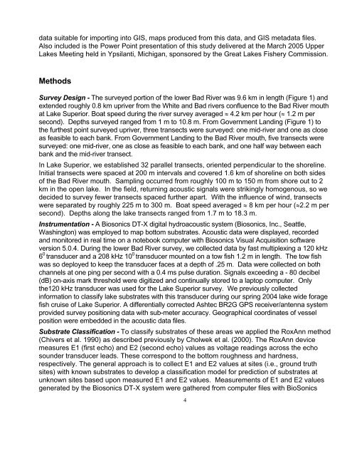
data suitable for import<strong>in</strong>g <strong>in</strong>to GIS, maps produced from this data, and GIS metadata files.Also <strong>in</strong>cluded is <strong>the</strong> Power Po<strong>in</strong>t presentation of this study delivered at <strong>the</strong> March 2005 Upper<strong>Lake</strong>s Meet<strong>in</strong>g held <strong>in</strong> Ypsilanti, Michigan, sponsored by <strong>the</strong> Great <strong>Lake</strong>s Fishery Commission.MethodsSurvey Design - The surveyed portion of <strong>the</strong> lower Bad River was 9.6 km <strong>in</strong> length (Figure 1) andextended roughly 0.8 km upriver from <strong>the</strong> White and Bad rivers confluence to <strong>the</strong> Bad River mouthat <strong>Lake</strong> Superior. Boat speed dur<strong>in</strong>g <strong>the</strong> river survey averaged ≈ 4.2 km per hour (≈ 1.2 m persecond). Depths surveyed ranged from 1 m to 10.8 m. From Government Land<strong>in</strong>g (Figure 1) to<strong>the</strong> fur<strong>the</strong>st po<strong>in</strong>t surveyed upriver, three transects were surveyed: one mid-river and one as closeas feasible to each bank. From Government Land<strong>in</strong>g to <strong>the</strong> Bad River mouth, five transects weresurveyed: one mid-river, one as close as feasible to each bank, and one half way between eachbank and <strong>the</strong> mid-river transect.In <strong>Lake</strong> Superior, we established 32 parallel transects, oriented perpendicular to <strong>the</strong> shorel<strong>in</strong>e.Initial transects were spaced at 200 m <strong>in</strong>tervals and covered 1.6 km of shorel<strong>in</strong>e on both sidesof <strong>the</strong> Bad River mouth. Sampl<strong>in</strong>g occurred from roughly 100 m to 150 m from shore out to 2km <strong>in</strong> <strong>the</strong> open lake. In <strong>the</strong> field, return<strong>in</strong>g acoustic signals were strik<strong>in</strong>gly homogenous, so wedecided to survey fewer transects spaced fur<strong>the</strong>r apart. With <strong>the</strong> <strong>in</strong>fluence of w<strong>in</strong>d, transectswere separated by roughly 225 m to 300 m. Boat speed averaged ≈ 8 km per hour (≈2.2 m persecond). Depths along <strong>the</strong> lake transects ranged from 1.7 m to 18.3 m.Instrumentation - A Biosonics DT-X digital hydroacoustic system (Biosonics, <strong>Inc</strong>., Seattle,Wash<strong>in</strong>gton) was employed to map bottom substrates. Acoustic data were displayed, recordedand monitored <strong>in</strong> real time on a notebook computer with Biosonics Visual Acquisition softwareversion 5.0.4. Dur<strong>in</strong>g <strong>the</strong> lower Bad River survey, we collected data by fast multiplex<strong>in</strong>g a 120 kHz6 0 transducer and a 208 kHz 10 0 transducer mounted on a tow fish 1.2 m <strong>in</strong> length. The tow fishwas so deployed to keep <strong>the</strong> transducer faces at a depth of .25 m. Data were collected on bothchannels at one p<strong>in</strong>g per second with a 0.4 ms pulse duration. Signals exceed<strong>in</strong>g a - 80 decibel(dB) on-axis mark threshold were digitized and cont<strong>in</strong>ually stored to a laptop computer. Only<strong>the</strong>120 kHz transducer was used for <strong>the</strong> <strong>Lake</strong> Superior survey. We previously collected<strong>in</strong>formation to classify lake substrates with this transducer dur<strong>in</strong>g our spr<strong>in</strong>g 2004 lake wide foragefish cruise of <strong>Lake</strong> Superior. A differentially corrected Ashtec BR2G GPS receiver/antenna systemprovided survey position<strong>in</strong>g data with sub-meter accuracy. Geographical coord<strong>in</strong>ates of vesselposition were embedded <strong>in</strong> <strong>the</strong> acoustic data files.Substrate Classification - To classify substrates of <strong>the</strong>se areas we applied <strong>the</strong> RoxAnn method(Chivers et al. 1990) as described previously by Cholwek et al. (2000). The RoxAnn devicemeasures E1 (first echo) and E2 (second echo) values as voltage read<strong>in</strong>gs across <strong>the</strong> echosounder transducer leads. These correspond to <strong>the</strong> bottom roughness and hardness,respectively. The general approach is to collect E1 and E2 values at sites (i.e., ground truthsites) with known substrates to develop a classification model for prediction of substrates atunknown sites based upon measured E1 and E2 values. Measurements of E1 and E2 valuesgenerated by <strong>the</strong> Biosonics DT-X system were ga<strong>the</strong>red from computer files with <strong>BioSonics</strong>4