Digital scanning sonar for fish feeding monitoring in ... - BioSonics, Inc
Digital scanning sonar for fish feeding monitoring in ... - BioSonics, Inc
Digital scanning sonar for fish feeding monitoring in ... - BioSonics, Inc

Create successful ePaper yourself
Turn your PDF publications into a flip-book with our unique Google optimized e-Paper software.
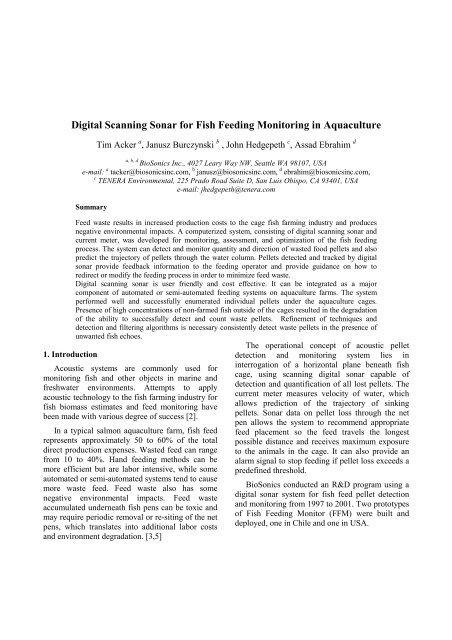
<strong>Digital</strong> Scann<strong>in</strong>g Sonar <strong>for</strong> Fish Feed<strong>in</strong>g Monitor<strong>in</strong>g <strong>in</strong> Aquaculture<br />
Tim Acker a , Janusz Burczynski b , John Hedgepeth c , Assad Ebrahim d<br />
a, b, d<br />
<strong>BioSonics</strong> <strong>Inc</strong>., 4027 Leary Way NW, Seattle WA 98107, USA<br />
e-mail: a tacker@biosonics<strong>in</strong>c.com, b janusz@biosonics<strong>in</strong>c.com, d ebrahim@biosonics<strong>in</strong>c.com,<br />
c TENERA Environmental, 225 Prado Road Suite D, San Luis Obispo, CA 93401, USA<br />
e-mail: jhedgepeth@tenera.com<br />
Summary<br />
Feed waste results <strong>in</strong> <strong>in</strong>creased production costs to the cage <strong>fish</strong> farm<strong>in</strong>g <strong>in</strong>dustry and produces<br />
negative environmental impacts. A computerized system, consist<strong>in</strong>g of digital <strong>scann<strong>in</strong>g</strong> <strong>sonar</strong> and<br />
current meter, was developed <strong>for</strong> <strong>monitor<strong>in</strong>g</strong>, assessment, and optimization of the <strong>fish</strong> <strong>feed<strong>in</strong>g</strong><br />
process. The system can detect and monitor quantity and direction of wasted food pellets and also<br />
predict the trajectory of pellets through the water column. Pellets detected and tracked by digital<br />
<strong>sonar</strong> provide feedback <strong>in</strong><strong>for</strong>mation to the <strong>feed<strong>in</strong>g</strong> operator and provide guidance on how to<br />
redirect or modify the <strong>feed<strong>in</strong>g</strong> process <strong>in</strong> order to m<strong>in</strong>imize feed waste.<br />
<strong>Digital</strong> <strong>scann<strong>in</strong>g</strong> <strong>sonar</strong> is user friendly and cost effective. It can be <strong>in</strong>tegrated as a major<br />
component of automated or semi-automated <strong>feed<strong>in</strong>g</strong> systems on aquaculture farms. The system<br />
per<strong>for</strong>med well and successfully enumerated <strong>in</strong>dividual pellets under the aquaculture cages.<br />
Presence of high concentrations of non-farmed <strong>fish</strong> outside of the cages resulted <strong>in</strong> the degradation<br />
of the ability to successfully detect and count waste pellets. Ref<strong>in</strong>ement of techniques and<br />
detection and filter<strong>in</strong>g algorithms is necessary consistently detect waste pellets <strong>in</strong> the presence of<br />
unwanted <strong>fish</strong> echoes.<br />
1. Introduction<br />
Acoustic systems are commonly used <strong>for</strong><br />
<strong>monitor<strong>in</strong>g</strong> <strong>fish</strong> and other objects <strong>in</strong> mar<strong>in</strong>e and<br />
freshwater environments. Attempts to apply<br />
acoustic technology to the <strong>fish</strong> farm<strong>in</strong>g <strong>in</strong>dustry <strong>for</strong><br />
<strong>fish</strong> biomass estimates and feed <strong>monitor<strong>in</strong>g</strong> have<br />
been made with various degree of success [2].<br />
In a typical salmon aquaculture farm, <strong>fish</strong> feed<br />
represents approximately 50 to 60% of the total<br />
direct production expenses. Wasted feed can range<br />
from 10 to 40%. Hand <strong>feed<strong>in</strong>g</strong> methods can be<br />
more efficient but are labor <strong>in</strong>tensive, while some<br />
automated or semi-automated systems tend to cause<br />
more waste feed. Feed waste also has some<br />
negative environmental impacts. Feed waste<br />
accumulated underneath <strong>fish</strong> pens can be toxic and<br />
may require periodic removal or re-sit<strong>in</strong>g of the net<br />
pens, which translates <strong>in</strong>to additional labor costs<br />
and environment degradation. [3,5]<br />
The operational concept of acoustic pellet<br />
detection and <strong>monitor<strong>in</strong>g</strong> system lies <strong>in</strong><br />
<strong>in</strong>terrogation of a horizontal plane beneath <strong>fish</strong><br />
cage, us<strong>in</strong>g <strong>scann<strong>in</strong>g</strong> digital <strong>sonar</strong> capable of<br />
detection and quantification of all lost pellets. The<br />
current meter measures velocity of water, which<br />
allows prediction of the trajectory of s<strong>in</strong>k<strong>in</strong>g<br />
pellets. Sonar data on pellet loss through the net<br />
pen allows the system to recommend appropriate<br />
feed placement so the feed travels the longest<br />
possible distance and receives maximum exposure<br />
to the animals <strong>in</strong> the cage. It can also provide an<br />
alarm signal to stop <strong>feed<strong>in</strong>g</strong> if pellet loss exceeds a<br />
predef<strong>in</strong>ed threshold.<br />
<strong>BioSonics</strong> conducted an R&D program us<strong>in</strong>g a<br />
digital <strong>sonar</strong> system <strong>for</strong> <strong>fish</strong> feed pellet detection<br />
and <strong>monitor<strong>in</strong>g</strong> from 1997 to 2001. Two prototypes<br />
of Fish Feed<strong>in</strong>g Monitor (FFM) were built and<br />
deployed, one <strong>in</strong> Chile and one <strong>in</strong> USA.
Figure 1. Representative concept <strong>for</strong> deployment of the Fish Feed<strong>in</strong>g Monitor underneath a <strong>fish</strong> farm cage<br />
Figure 1 shows the conceptual diagram of a net<br />
pen, FFM deployment, and waste feed. Fish are fed<br />
with pellets rang<strong>in</strong>g <strong>in</strong> size from 3 to 12 mm,<br />
depend<strong>in</strong>g of <strong>fish</strong> size. Pellets are delivered to <strong>fish</strong><br />
<strong>in</strong> the cage manually or mechanically. Some of the<br />
pellets are eaten by <strong>fish</strong> the balance pass through<br />
the cage. The trajectory of s<strong>in</strong>k<strong>in</strong>g pellets depends<br />
on pellet size, surface delivery po<strong>in</strong>t and velocity of<br />
the water current (speed and direction).<br />
2. Material and Method<br />
different current velocities <strong>for</strong> different pellet sizes.<br />
Selected results are presented <strong>in</strong> Table II.<br />
Table I. Selected results from measurements of Target<br />
Strength of pellets us<strong>in</strong>g 200 kHz, 6° split beam digital<br />
track<strong>in</strong>g <strong>sonar</strong>. Pulse duration 0.4 ms, 10 p<strong>in</strong>gs/second,<br />
pellet orientation vertical.<br />
Pellet Size [mm] Average [dB] Average TS [dB] Standard<br />
Deviation<br />
3.5 -59.4 -62.1 3.4<br />
8.5 -53.7 -55.0 4.7<br />
11 -47.6 -48.9 3.8<br />
2.1. Pellet S<strong>in</strong>k<strong>in</strong>g Model<br />
From 1997 to 1999 <strong>BioSonics</strong> conducted a<br />
series of experiments on <strong>fish</strong> farms, <strong>in</strong> Lake Union<br />
and <strong>in</strong> the University of Wash<strong>in</strong>gton Hydraulic<br />
Laboratory on acoustic measurements, track<strong>in</strong>g,<br />
and <strong>monitor<strong>in</strong>g</strong> of s<strong>in</strong>k<strong>in</strong>g <strong>fish</strong> feed pellets.<br />
Pellets were measured and tracked with<br />
<strong>BioSonics</strong> 201 kHz and 420 kHz split beam digital<br />
echosounders and an active track<strong>in</strong>g <strong>sonar</strong> system<br />
[4]. Acoustic measurements from various pellet<br />
sizes are presented <strong>in</strong> Table I. S<strong>in</strong>k rate (speed and<br />
direction) of <strong>in</strong>dividual pellets was measured under<br />
Table II. Mean S<strong>in</strong>k<strong>in</strong>g Rates (MSR) and Standard<br />
Deviations (SD) of three feed pellet sizes (3.5 mm, 8.5<br />
mm and 11 mm) calculated from data acquired with a<br />
split-beam track<strong>in</strong>g <strong>sonar</strong> 201 kHz, us<strong>in</strong>g pulse duration<br />
τ = 0.1ms and τ = 0.4 ms.<br />
τ = 0.1 [ms] 3.5 mm 8.5 mm 11.0 mm<br />
MSR [m/s] 0.134 0.166 0.201<br />
SD. 0.009 0.006 0.022<br />
τ = 0.4 [ms] 3.5 mm 8.5 mm 11.0 mm<br />
MSR [m/s] 0.121 0.166 0.208<br />
SD 0.004 0.006 0.027
2.2. Pellets Detection and Quantification Algorithm<br />
Numerical echo-<strong>in</strong>tegration algorithms were<br />
developed and tested to count lost pellets. The<br />
method used to determ<strong>in</strong>e pellet loss with a <strong>sonar</strong><br />
sweep or conical scan uses the concept of flux<br />
through a control area, as shown on Figure 2.<br />
The calculation of the flux method of the pellet<br />
detection assumes a known s<strong>in</strong>k<strong>in</strong>g rate of pellets,<br />
which can be determ<strong>in</strong>ed <strong>in</strong> situ us<strong>in</strong>g target<br />
track<strong>in</strong>g, from a model, or from <strong>in</strong> vitro<br />
experiments. Calculation of total pellet loss<br />
requires an estimate of the area through which feed<br />
is lost. As a first approximation, it will be the area<br />
above the conical scan, which is a planar slice<br />
where the <strong>sonar</strong> beam axis <strong>in</strong>tersects a sphere. This<br />
area corresponds directly to the volume that is echo<br />
<strong>in</strong>tegrated <strong>for</strong> density estimates:<br />
⎛ ψ ⎞<br />
A = ⎜ ⎟<br />
⎞<br />
⎜<br />
π<br />
π<br />
⎟ ⎛ r<br />
2<br />
− r<br />
2<br />
(1)<br />
⎝ 2 ⎠⎝<br />
2 1 ⎠<br />
where: A is a planar area of flow [m 2 ],<br />
ψ is the angle swept [radians],<br />
r 1 is the start range of a p<strong>in</strong>g [m] and<br />
r 2 is the end range of a p<strong>in</strong>g [m].<br />
Pellets Fall<br />
Upper<br />
Frustum<br />
Sonar<br />
Lower<br />
Frustum<br />
Planar<br />
Area<br />
Figure 2. Diagram of the method used to determ<strong>in</strong>e the sample<br />
volume of the <strong>sonar</strong> sweep.<br />
The number of lost pellets per unit of time is<br />
equal to the density times the flow of pellets<br />
through the area (m 3 /s). The density of pellets was<br />
estimated by echo <strong>in</strong>tegration <strong>in</strong> the <strong>feed<strong>in</strong>g</strong><br />
monitor program. The flow of pellets is equal to<br />
the s<strong>in</strong>k<strong>in</strong>g rate times the area. There<strong>for</strong>e, the<br />
number of pellets lost per unit of time is:<br />
P<br />
= A ρ ω . (2)<br />
t<br />
where: P is number of lost pellets,<br />
t is time [s],<br />
ρ is density of pellets [number / m 3 ],<br />
ω is s<strong>in</strong>k<strong>in</strong>g rate of pellets [m/s].<br />
Total number of pellets P t lost can be calculated<br />
by multiply<strong>in</strong>g the above loss rate, times the time<br />
<strong>in</strong>terval of <strong>monitor<strong>in</strong>g</strong> the <strong>feed<strong>in</strong>g</strong> T.<br />
P<br />
P t = T<br />
(3)<br />
t<br />
The comb<strong>in</strong>ed loss equation is, lett<strong>in</strong>g<br />
<strong>monitor<strong>in</strong>g</strong> time be Τ :<br />
P t = A ρ ω T (4)<br />
<strong>BioSonics</strong> BioMonitor program reports densities<br />
at each <strong>in</strong>dividual p<strong>in</strong>g (p), and cumulative sum of<br />
densities over all p<strong>in</strong>gs (n), i.e.<br />
ρ and ∑ ρ .<br />
p<br />
n<br />
p=<br />
1<br />
Given constant p<strong>in</strong>g rate and simplify<strong>in</strong>g, the loss<br />
equation can be written:<br />
n<br />
Pt = Aω λ ∑ ρ p<br />
(5)<br />
p=<br />
1<br />
where: λ is p<strong>in</strong>g rate [p<strong>in</strong>gs/s].<br />
3. System Description<br />
The Fish Feed<strong>in</strong>g Monitor (FFM) consists of the<br />
follow<strong>in</strong>g modules: digital <strong>sonar</strong>, current meter, and<br />
computer and software <strong>for</strong> <strong>in</strong>strument control, data<br />
storage, process<strong>in</strong>g and display.<br />
The hardware consists of a <strong>BioSonics</strong> digital<br />
echosounder, a 200 kHz, 6° s<strong>in</strong>gle beam transducer<br />
<strong>in</strong>stalled on a rotator unit, a current meter, and two<br />
computers <strong>for</strong> <strong>in</strong>strument control, data acquisition,<br />
analysis, and data storage.<br />
The transducer, rotator unit and current meter<br />
are deployed below the cage (Figure 1). This<br />
placement allows detection of waste feed pellets<br />
that pass out of the cage and <strong>monitor<strong>in</strong>g</strong> of water<br />
current. S<strong>in</strong>ce <strong>in</strong>dividual pellets have a low target<br />
strength and they can best be detected <strong>in</strong> a small<br />
sampl<strong>in</strong>g volume. The cluttered environment under<br />
the cage (<strong>fish</strong>, cables, anchors, etc) and the close<br />
proximity of the transducer to the cage require a<br />
p
transducer with very low side lobes and <strong>BioSonics</strong><br />
transducers have side lobes of less than –30 dB.<br />
The research prototype of FFM was built around<br />
the exist<strong>in</strong>g technology of the <strong>BioSonics</strong> DE Model<br />
200 kHz, 6 digital <strong>sonar</strong> system [1].<br />
Modifications to the digital <strong>sonar</strong> eng<strong>in</strong>e (both<br />
hardware and software <strong>for</strong> data acquisition) were<br />
necessary to accommodate the <strong>scann<strong>in</strong>g</strong><br />
rotator/transducer assembly. Data file <strong>for</strong> each p<strong>in</strong>g<br />
are stored on the operat<strong>in</strong>g computer hard drive.<br />
Data files conta<strong>in</strong> general <strong>in</strong><strong>for</strong>mation about <strong>sonar</strong><br />
system parameters (e.g. frequency, beamwidth,<br />
transmitted power, receiver sensitivity, pulse<br />
length, threshold etc.), <strong>in</strong><strong>for</strong>mation <strong>for</strong> each<br />
<strong>in</strong>dividual p<strong>in</strong>g <strong>in</strong> a <strong>for</strong>m of echo envelope<br />
amplitude (digitized at a frequency of 41.33 kHz),<br />
digitized phase <strong>in</strong><strong>for</strong>mation of an echo signal (<strong>in</strong><br />
split-beam mode), and rotator motor orientation.<br />
The FFM also <strong>in</strong>corporates <strong>in</strong><strong>for</strong>mation from a<br />
current meter (Falmouth Model ACM-CBP-S, two<br />
component digital Doppler current meter) with<br />
compass.<br />
Several modules of the FFM system were<br />
designed, developed and implemented specifically<br />
<strong>for</strong> this project. These are as follows:<br />
• Scann<strong>in</strong>g Rotator allow<strong>in</strong>g changes to pan and<br />
tilt angle of transducer,<br />
• Rotator Motor drivers and Power Supply,<br />
• Software <strong>for</strong> <strong>scann<strong>in</strong>g</strong> rotator motor control<br />
“BioScan”,<br />
• Lost pellet detection software: “BioMonitor”<br />
with Plane Position Indicator (PPI) of detected<br />
pellets, and lost pellet counter.<br />
3.1. Rotator and Scann<strong>in</strong>g Software (BioScan)<br />
The rotator assembly consists of two stepper<br />
motors (pan and tilt axis) and gearboxes, <strong>in</strong>stalled<br />
<strong>in</strong> an oil-filled, sealed hous<strong>in</strong>g. Two programmable<br />
motor controllers and power unit <strong>for</strong> the rotator are<br />
<strong>in</strong>stalled <strong>in</strong> a separate weatherproof case.<br />
BioScan software was developed <strong>for</strong> control of<br />
the dual-axis rotator step-motors, and is <strong>in</strong>tegrated<br />
with the data acquisition and waste feed <strong>monitor<strong>in</strong>g</strong><br />
software (BioMonitor). BioScan allows <strong>for</strong> control<br />
of the speed, acceleration and deceleration<br />
characteristics of the rotator. The user can control<br />
the position of the motors <strong>in</strong> real-time, program the<br />
movement, or select pre-programmed <strong>scann<strong>in</strong>g</strong><br />
patterns.<br />
3.2. BioMonitor, Waste Feed Monitor<strong>in</strong>g Software.<br />
The BioMonitor software was developed <strong>for</strong><br />
pellet detection, quantification, and visual display.<br />
It receives TCP/IP stream<strong>in</strong>g hydro acoustic data<br />
from the digital echosounder transducer and uses a<br />
high-resolution color echogram, <strong>in</strong> a Plane Position<br />
Indicator (PPI) <strong>for</strong>mat, to display the location and<br />
quantity of lost pellets.<br />
An example of the BioMonitor graphical user<br />
<strong>in</strong>terface is shown <strong>in</strong> Figure 3. The upper part of<br />
the display is the PPI, which shows the range and<br />
acoustic image of detected pellets.<br />
The echo strength of detected pellets is color<br />
coded <strong>in</strong> decibels (dB) <strong>for</strong> graphic display on the<br />
PPI. Lower strength signals (‘cooler’ colors)<br />
<strong>in</strong>dicate small amounts of detected pellets. In the<br />
case of detection of <strong>in</strong>dividual pellets, the target<br />
strength (dB) is directly related to pellet size.<br />
Higher strength (‘hotter’ colors) <strong>in</strong>dicates high<br />
densities of pellets detected.<br />
4. System Test<strong>in</strong>g and Deployment<br />
4.1. System Calibration and Test<strong>in</strong>g.<br />
Prior to <strong>in</strong>tegration of the system components<br />
<strong>for</strong> the FFM, the digital echosounder and motor<br />
control system were calibrated and tested as<br />
<strong>in</strong>dividual modules. A standard target test was also<br />
per<strong>for</strong>med to verify the system per<strong>for</strong>mance<br />
measured dur<strong>in</strong>g standard hydrophone calibration.<br />
After complet<strong>in</strong>g tests of the <strong>in</strong>dividual<br />
modules, the system was <strong>in</strong>tegrated and tested<br />
under various operat<strong>in</strong>g conditions <strong>in</strong> the<br />
calibration tank. In particular, the system’s noise<br />
levels were exam<strong>in</strong>ed dur<strong>in</strong>g active <strong>scann<strong>in</strong>g</strong> of the<br />
rotator motors to determ<strong>in</strong>e if there was any<br />
acoustic signal <strong>in</strong>terference attributable to the<br />
rotators. Results <strong>in</strong>dicate that the noise level of the<br />
system was satisfactory <strong>for</strong> detect<strong>in</strong>g the smallest<br />
of <strong>in</strong>dividual pellets (Target Strength = –65 dB) at a<br />
range of 25 meters, which was the expected<br />
maximum operat<strong>in</strong>g range of the system at the <strong>fish</strong><br />
farm.<br />
Upon completion of the laboratory tests, the<br />
<strong>in</strong>tegrated system was tested at a nearby boat dock.<br />
The purpose of these <strong>in</strong>termediary tests was to<br />
allow further exam<strong>in</strong>ation of the systems<br />
per<strong>for</strong>mance <strong>in</strong> an environment that more closely<br />
approximated that of the <strong>fish</strong> farm.
4.2. Deployment of FFM a Local Fish Farm.<br />
The prototype FFM was tested at the Northwest<br />
Sea Farms net pen facility, located on Ba<strong>in</strong>bridge<br />
Island, Wash<strong>in</strong>gton. Initial tests were conducted<br />
below an empty net pen, with the primary goal of<br />
confirm<strong>in</strong>g the ability of the FFM to detect pellets<br />
under the conditions presented at a typical <strong>fish</strong><br />
farm<strong>in</strong>g facility.<br />
For these tests, the rotator/transducer assembly<br />
was attached to a mount<strong>in</strong>g pole, such that the pole<br />
could be adjusted to any depth <strong>in</strong> the water column<br />
up to 12 meters deep below the <strong>fish</strong> cage.<br />
The rotator/transducer assembly was then<br />
deployed between two net pens conta<strong>in</strong><strong>in</strong>g <strong>fish</strong>, to<br />
test the <strong>sonar</strong> system’s ability to detect and quantify<br />
pellet loss below a functional net pen. Dur<strong>in</strong>g these<br />
tests, <strong>fish</strong> were fed us<strong>in</strong>g the automatic airlift<br />
feeders (IAS “Aero Spreader” Systems Series 1001<br />
SE) used at the <strong>fish</strong> farm. With these feeders,<br />
pellets were blown by air, and spread over the<br />
entire surface area of the net pen.<br />
5. Results and Discussion<br />
In general, the Fish Feed<strong>in</strong>g Monitor per<strong>for</strong>med<br />
well. The system was found to have a high<br />
Signal/Noise ratio, with no noise or <strong>in</strong>terference<br />
from the rotator motors on the acoustic signal. We<br />
demonstrated that we were able to detect <strong>in</strong>dividual<br />
pellets, below the unoccupied net pen, at a range of<br />
25 meters, which is the anticipated range <strong>for</strong> the<br />
commercial prototype. The Signal/Noise ratio was<br />
better than 6 dB <strong>for</strong> a –60 dB target.<br />
The one major problem we encountered <strong>in</strong> the<br />
field-test<strong>in</strong>g of the FFM was due to the presence of<br />
numerous small <strong>fish</strong> beneath the net pens dur<strong>in</strong>g<br />
<strong>feed<strong>in</strong>g</strong> operations. Although this result was not<br />
unexpected (prelim<strong>in</strong>ary test<strong>in</strong>g showed evidence<br />
of small resident <strong>fish</strong> populations), the magnitude<br />
of <strong>fish</strong> density far exceeded our expectations.<br />
Fish aggregations below <strong>fish</strong> farm cages were<br />
attracted to the wasted <strong>fish</strong> food and appeared <strong>in</strong><br />
significant numbers dur<strong>in</strong>g field trials. Although<br />
pellets can be readily detected and quantified by the<br />
digital <strong>sonar</strong> <strong>in</strong> absence of these <strong>fish</strong>, their<br />
abundance <strong>in</strong> the sample volume tends to obscure<br />
the bulk of the s<strong>in</strong>k<strong>in</strong>g pellets, mak<strong>in</strong>g pellet<br />
quantification was impossible with the exist<strong>in</strong>g<br />
technology. It is unknown, at this time, if this<br />
abundance of small <strong>fish</strong> is a seasonal issue or<br />
whether it will be a persistent problem.<br />
Detection of s<strong>in</strong>k<strong>in</strong>g pellets <strong>in</strong> the presence <strong>fish</strong><br />
under the cage is possible, while quantify<strong>in</strong>g them<br />
under these conditions will be more difficult.<br />
Figure 4 illustrates the situation encountered when<br />
the small <strong>fish</strong> are present. This problem will be<br />
addressed <strong>in</strong> a special research project.<br />
Consider<strong>in</strong>g different “behavior” between feed<br />
pellets and <strong>fish</strong>, and us<strong>in</strong>g various techniques of<br />
echo signal process<strong>in</strong>g (such as neural networks<br />
and fuzzy logic classifiers) can potentially be used<br />
<strong>for</strong> separat<strong>in</strong>g pellet and <strong>fish</strong> signals.<br />
Acknowledgements<br />
We thank Bra<strong>in</strong> McFadden (of <strong>BioSonics</strong>) <strong>for</strong><br />
his creative contributions <strong>in</strong> fieldwork. Part of this<br />
research was supported by the US Department of<br />
Agriculture SBIR grant # 2001-00383. Another part<br />
of this project was done under a jo<strong>in</strong>t research<br />
program between <strong>BioSonics</strong> and IFOP of Chile.<br />
References<br />
[1] W. C. Acker, J. Burczynski, J. Dawson, J. Hedgepeth<br />
and D. Wigg<strong>in</strong>s: <strong>Digital</strong> Transducers: A New Sonar<br />
Technology, Sea Technology 40 (1999) pp. 31-35.<br />
[2] A. Bjordal, J.E. Juell, T. L<strong>in</strong>dem and A. Ferno:<br />
Hydroacoustic <strong>monitor<strong>in</strong>g</strong> and <strong>feed<strong>in</strong>g</strong> control <strong>in</strong> cage<br />
rear<strong>in</strong>g of Atlantic salmon, Fish Farm<strong>in</strong>g Technology<br />
(1993) pp. 203-208.<br />
[3] K.P. Ang and R.J. Petrell: Pellet wastage, and<br />
subsurface and surface <strong>feed<strong>in</strong>g</strong> behaviors associated with<br />
different <strong>feed<strong>in</strong>g</strong> systems <strong>in</strong> sea cage farm<strong>in</strong>g of<br />
salmonids, Aquacultural Eng<strong>in</strong>eer<strong>in</strong>g 18 (1998) pp. 95-<br />
115.<br />
[4] J. Hedgepeth, D. Fuhriman, D. Geist and R. Johnson:<br />
Fish movement measured by track<strong>in</strong>g radar type acoustic<br />
transducers, Proceed<strong>in</strong>gs of the Fourth European<br />
Conference on Underwater Acoustics, Rome, 1998, pp.<br />
199-204.<br />
[5] J.E. Juell, D.M. Furevik and A. Bjordal: Demand<br />
Feed<strong>in</strong>g <strong>in</strong> Salmon Farm<strong>in</strong>g by Hydroacoustic Food<br />
Detection, Aquacultural Eng<strong>in</strong>eer<strong>in</strong>g 12 (1993) pp. 155 –<br />
167.
Figure 3. Screen capture from <strong>BioSonics</strong> PPI and pellet detection monitor.<br />
Individual feed pellet traces are <strong>in</strong>dicated, <strong>in</strong> blue, detected at a range of 4 to 8<br />
meters from the FFM. The graph <strong>in</strong> the lower part of figure <strong>in</strong>dicates the number<br />
of pellets <strong>in</strong> each detection and also cumulative value as TOTAL LOSS.<br />
Echoes from<br />
resident <strong>fish</strong> and<br />
from s<strong>in</strong>k<strong>in</strong>g<br />
pellets<br />
Echoes from<br />
s<strong>in</strong>k<strong>in</strong>g pellets<br />
Figure 4. Screen captures <strong>for</strong> <strong>BioSonics</strong> data acquisition software. The <strong>sonar</strong> transducer was<br />
deployed below <strong>fish</strong> cages at the aquaculture facility. Depth range of both echograms 1 to 20<br />
meters. Echo signal level is color-coded; red color <strong>in</strong>dicates largest signal level, and “cooler” colors<br />
<strong>in</strong>dicate signal of lower value. The echogram on left displays a mixture of echo traces from resident<br />
<strong>fish</strong> and from feed pellets with <strong>fish</strong> mov<strong>in</strong>g <strong>in</strong> a random fashion. It was difficult to dist<strong>in</strong>guish<br />
between <strong>fish</strong> and pellets echoes dur<strong>in</strong>g data collection. The right echogram shows only pellet<br />
echoes, <strong>in</strong> the absence of <strong>fish</strong>. The shape of echo trace from s<strong>in</strong>k<strong>in</strong>g pellet is straight l<strong>in</strong>e with a<br />
slope towards right low corner of echogram, <strong>in</strong>dicative of the pellet trajectory (behavior).