BRAKES & CLUTCHES
BRAKES & CLUTCHES
BRAKES & CLUTCHES

Create successful ePaper yourself
Turn your PDF publications into a flip-book with our unique Google optimized e-Paper software.
Brakes & Clutches Deltran PT<br />
Mounting Requirements<br />
Mounting Requirements for Super CB, Standard CB, SAC, SP, ACCE and BIMAC Units<br />
(All plated mounted wrap spring products)<br />
Horizontal & Vertical<br />
Mounting<br />
The Genuine Wrap Spring clutches are<br />
self-contained packaged products<br />
which are easy to mount. A few simple<br />
precautions should be taken to ensure<br />
maximum life.<br />
All Genuine Wrap Spring clutch products<br />
are designed for parallel shaft<br />
applications where they are fully supported<br />
by the shaft on which they are<br />
mounted. In the case of wrap spring<br />
clutch/brakes (CB) the through shaft is<br />
always the output. Connecting the<br />
parallel shaft to the CB input can be<br />
accomplished by use of a belt, chain or<br />
gear drive. CB models must be mounted<br />
with the shaft(s) in a horizontal<br />
position (Figure 1). If vertical mounting<br />
is required, see Figure 2.<br />
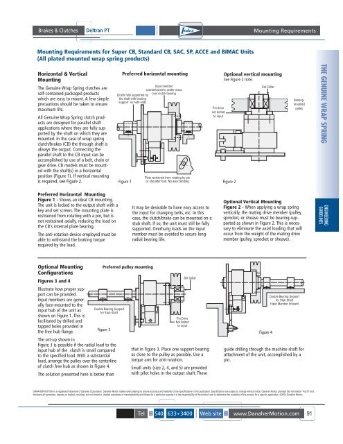
Preferred Horizontal Mounting<br />
Figure 1 - Shows an ideal CB mounting.<br />
The unit is locked to the output shaft with a<br />
key and set screws. The mounting plate is<br />
restrained from rotating with a pin, but is<br />
not restrained axially, reducing the load on<br />
the CB’s internal plate bearing.<br />
The anti-rotation device employed must be<br />
able to withstand the braking torque<br />
required by the load.<br />
Optional Mounting<br />
Configurations<br />
Figures 3 and 4<br />
Illustrate how proper support<br />
can be provided.<br />
Input members are generally<br />
face-mounted to the<br />
input hub of the unit as<br />
shown on Figure 1. This is<br />
facilitated by drilled and<br />
tapped holes provided in<br />
the free hub flange.<br />
Double Bearing Support<br />
for Stub Shaft<br />
Figure 3<br />
The set-up shown in<br />
Figure 3 is possible if the radial load to the<br />
input hub of the clutch is small compared<br />
to the specified load. With a substantial<br />
load, arrange the pulley over the centerline<br />
of clutch free hub as shown in Figure 4.<br />
The solution presented here is better than<br />
Preferred horizontal mounting<br />
Clutch fully supported by<br />
the shaft with bearing<br />
support on both ends<br />
Figure 1<br />
Preferred pulley mounting<br />
Input member<br />
counterbored to center mass<br />
over clutch bearing<br />
Plate restrained from rotating by pin<br />
or shoulder bolt. No axial binding<br />
It may be desirable to have easy access to<br />
the input for changing belts, etc. In this<br />
case, the clutch/brake can be mounted on a<br />
stub shaft. If so, the unit must still be fully<br />
supported. Overhung loads on the input<br />
member must be avoided to secure long<br />
radial bearing life.<br />
DANAHER MOTION is a registered trademark of Danaher Corporation. Danaher Motion makes every attempt to ensure accuracy and reliability of the specifications in this publication. Specifications are subject to change without notice. Danaher Motion provides this information "AS IS" and<br />
disclaims all warranties, express or implied, including, but not limited to, implied warranties of merchantability and fitness for a particular purpose.It is the responsibility of the product user to determine the suitability of this product for a specific application. ©2004 Danaher Motion.<br />
+<br />
Pin Drive<br />
Not Bolted<br />
to Input<br />
Set Collar<br />
that in Figure 3. Place one support bearing<br />
as close to the pulley as possible. Use a<br />
torque arm for anti-rotation.<br />
Small units (size 2, 4, and 5) are provided<br />
with pilot holes in the output shaft. These<br />
Pin drive<br />
not bolted<br />
to input<br />
Optional vertical mounting<br />
See Figure 2 note.<br />
Figure 2<br />
Set Collar<br />
Figure 4<br />
Bearingmounted<br />
pulley<br />
Optional Vertical Mounting<br />
Figure 2 - When applying a wrap spring<br />
vertically, the mating drive member (pulley,<br />
sprocket, or sheave must be bearing-supported<br />
as shown in Figure 2. This is necessary<br />
to eliminate the axial loading that will<br />
occur from the weight of the mating drive<br />
member (pulley, sprocket or sheave).<br />
Double Bearing Support<br />
for Stub Shaft<br />
Input Member Inboard<br />
guide drilling through the machine shaft for<br />
attachment of the unit, accomplished by a<br />
pin.<br />
Tel : 540 633 3400 Web site : www.DanaherMotion.com 91<br />
THE GENUINE WRAP SPRING<br />
ENGINEERING<br />
GUIDELINES