Diesel distributor fuel-injection pumps VE - K-Jet.org
Diesel distributor fuel-injection pumps VE - K-Jet.org
Diesel distributor fuel-injection pumps VE - K-Jet.org

You also want an ePaper? Increase the reach of your titles
YUMPU automatically turns print PDFs into web optimized ePapers that Google loves.
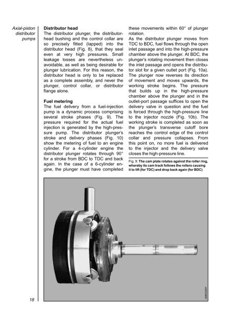
Axial-piston<strong>distributor</strong><strong>pumps</strong>Distributor headThe <strong>distributor</strong> plunger, the <strong>distributor</strong>headbushing and the control collar areso precisely fitted (lapped) into the<strong>distributor</strong> head (Fig. 8), that they sealeven at very high pressures. Smallleakage losses are nevertheless unavoidable,as well as being desirable forplunger lubrication. For this reason, the<strong>distributor</strong> head is only to be replacedas a complete assembly, and never theplunger, control collar, or <strong>distributor</strong>flange alone.Fuel meteringThe <strong>fuel</strong> delivery from a <strong>fuel</strong>-<strong>injection</strong>pump is a dynamic process comprisingseveral stroke phases (Fig. 9). Thepressure required for the actual <strong>fuel</strong><strong>injection</strong> is generated by the high-pressurepump. The <strong>distributor</strong> plunger’sstroke and delivery phases (Fig. 10)show the metering of <strong>fuel</strong> to an enginecylinder. For a 4-cylinder engine the<strong>distributor</strong> plunger rotates through 90°for a stroke from BDC to TDC and backagain. In the case of a 6-cylinder engine,the plunger must have completedthese movements within 60° of plungerrotation.As the <strong>distributor</strong> plunger moves fromTDC to BDC, <strong>fuel</strong> flows through the openinlet passage and into the high-pressurechamber above the plunger. At BDC, theplunger’s rotating movement then closesthe inlet passage and opens the <strong>distributor</strong>slot for a given outlet port (Fig. 10a).The plunger now reverses its directionof movement and moves upwards, theworking stroke begins. The pressurethat builds up in the high-pressurechamber above the plunger and in theoutlet-port passage suffices to open thedelivery valve in question and the <strong>fuel</strong>is forced through the high-pressure lineto the injector nozzle (Fig. 10b). Theworking stroke is completed as soon asthe plunger’s transverse cutoff borereaches the control edge of the controlcollar and pressure collapses. Fromthis point on, no more <strong>fuel</strong> is deliveredto the injector and the delivery valvecloses the high-pressure line.Fig. 9: The cam plate rotates against the roller ring,whereby its cam track follows the rollers causingit to lift (for TDC) and drop back again (for BDC)18UMK0328Y