Diesel distributor fuel-injection pumps VE - K-Jet.org
Diesel distributor fuel-injection pumps VE - K-Jet.org
Diesel distributor fuel-injection pumps VE - K-Jet.org

You also want an ePaper? Increase the reach of your titles
YUMPU automatically turns print PDFs into web optimized ePapers that Google loves.
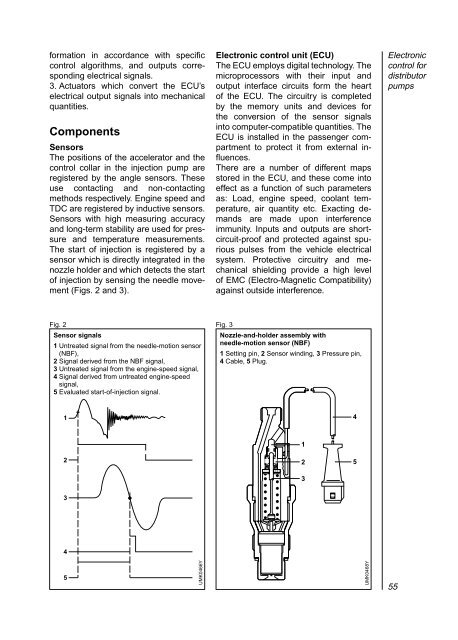
formation in accordance with specificcontrol algorithms, and outputs correspondingelectrical signals.3. Actuators which convert the ECU’selectrical output signals into mechanicalquantities.ComponentsSensorsThe positions of the accelerator and thecontrol collar in the <strong>injection</strong> pump areregistered by the angle sensors. Theseuse contacting and non-contactingmethods respectively. Engine speed andTDC are registered by inductive sensors.Sensors with high measuring accuracyand long-term stability are used for pressureand temperature measurements.The start of <strong>injection</strong> is registered by asensor which is directly integrated in thenozzle holder and which detects the startof <strong>injection</strong> by sensing the needle movement(Figs. 2 and 3).Electronic control unit (ECU)The ECU employs digital technology. Themicroprocessors with their input andoutput interface circuits form the heartof the ECU. The circuitry is completedby the memory units and devices forthe conversion of the sensor signalsinto computer-compatible quantities. TheECU is installed in the passenger compartmentto protect it from external influences.There are a number of different mapsstored in the ECU, and these come intoeffect as a function of such parametersas: Load, engine speed, coolant temperature,air quantity etc. Exacting demandsare made upon interferenceimmunity. Inputs and outputs are shortcircuit-proofand protected against spuriouspulses from the vehicle electricalsystem. Protective circuitry and mechanicalshielding provide a high levelof EMC (Electro-Magnetic Compatibility)against outside interference.Electroniccontrol for<strong>distributor</strong><strong>pumps</strong>Fig. 2 Fig. 3Sensor signals1 Untreated signal from the needle-motion sensor(NBF),2 Signal derived from the NBF signal,3 Untreated signal from the engine-speed signal,4 Signal derived from untreated engine-speedsignal,5 Evaluated start-of-<strong>injection</strong> signal.Nozzle-and-holder assembly withneedle-motion sensor (NBF)1 Setting pin, 2 Sensor winding, 3 Pressure pin,4 Cable, 5 Plug.1421235345UMK0466YUMK0468Y55