Diesel distributor fuel-injection pumps VE - K-Jet.org
Diesel distributor fuel-injection pumps VE - K-Jet.org
Diesel distributor fuel-injection pumps VE - K-Jet.org

You also want an ePaper? Increase the reach of your titles
YUMPU automatically turns print PDFs into web optimized ePapers that Google loves.
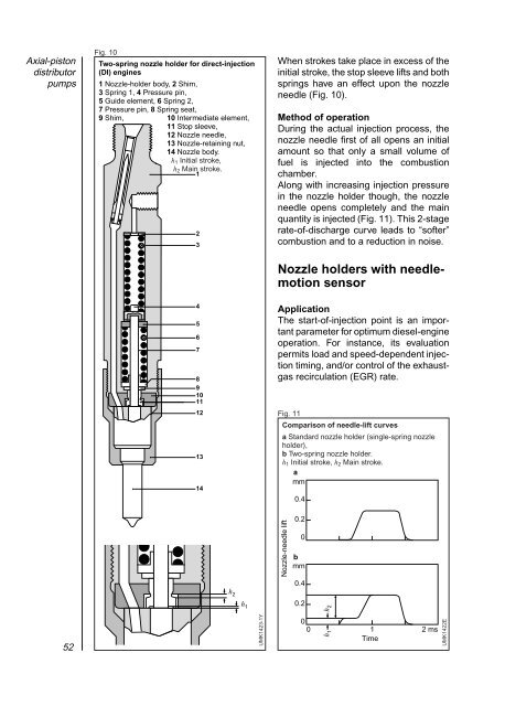
Axial-piston<strong>distributor</strong><strong>pumps</strong>Fig. 10Two-spring nozzle holder for direct-<strong>injection</strong>(DI) engines1 Nozzle-holder body, 2 Shim,3 Spring 1, 4 Pressure pin,5 Guide element, 6 Spring 2,7 Pressure pin, 8 Spring seat,9 Shim, 10 Intermediate element,11 Stop sleeve,12 Nozzle needle,13 Nozzle-retaining nut,14 Nozzle body.h 1 Initial stroke,h 2 Main stroke.123When strokes take place in excess of theinitial stroke, the stop sleeve lifts and bothsprings have an effect upon the nozzleneedle (Fig. 10).Method of operationDuring the actual <strong>injection</strong> process, thenozzle needle first of all opens an initialamount so that only a small volume of<strong>fuel</strong> is injected into the combustionchamber.Along with increasing <strong>injection</strong> pressurein the nozzle holder though, the nozzleneedle opens completely and the mainquantity is injected (Fig. 11). This 2-stagerate-of-discharge curve leads to “softer”combustion and to a reduction in noise.Nozzle holders with needlemotionsensor4567891011121314ApplicationThe start-of-<strong>injection</strong> point is an importantparameter for optimum diesel-engineoperation. For instance, its evaluationpermits load and speed-dependent <strong>injection</strong>timing, and/or control of the exhaustgasrecirculation (EGR) rate.Fig. 11Comparison of needle-lift curvesa Standard nozzle holder (single-spring nozzleholder),b Two-spring nozzle holder.h 1 Initial stroke, h 2 Main stroke.amm0.40.20bmm0.4h 2h 1Nozzle-needle lift0.2h 252UMK1423-1Y00 1Timeh 12 msUMK1422E