ICAF System with pneumatic release - Fireflex.com
ICAF System with pneumatic release - Fireflex.com
ICAF System with pneumatic release - Fireflex.com

Create successful ePaper yourself
Turn your PDF publications into a flip-book with our unique Google optimized e-Paper software.
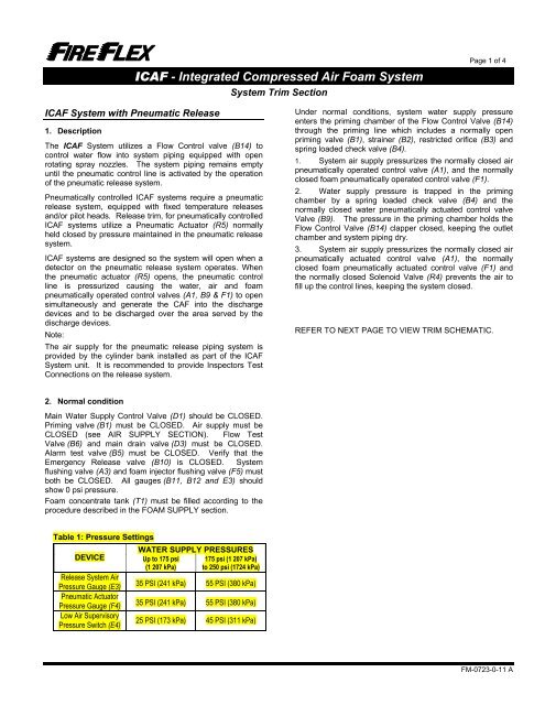
<strong>ICAF</strong> - Integrated Compressed Air Foam <strong>System</strong><strong>System</strong> Trim SectionPage 1 of 4<strong>ICAF</strong> <strong>System</strong> <strong>with</strong> Pneumatic Release1. DescriptionThe <strong>ICAF</strong> <strong>System</strong> utilizes a Flow Control valve (B14) tocontrol water flow into system piping equipped <strong>with</strong> openrotating spray nozzles. The system piping remains emptyuntil the <strong>pneumatic</strong> control line is activated by the operationof the <strong>pneumatic</strong> <strong>release</strong> system.Pneumatically controlled <strong>ICAF</strong> systems require a <strong>pneumatic</strong><strong>release</strong> system, equipped <strong>with</strong> fixed temperature <strong>release</strong>sand/or pilot heads. Release trim, for <strong>pneumatic</strong>ally controlled<strong>ICAF</strong> systems utilize a Pneumatic Actuator (R5) normallyheld closed by pressure maintained in the <strong>pneumatic</strong> <strong>release</strong>system.<strong>ICAF</strong> systems are designed so the system will open when adetector on the <strong>pneumatic</strong> <strong>release</strong> system operates. Whenthe <strong>pneumatic</strong> actuator (R5) opens, the <strong>pneumatic</strong> controlline is pressurized causing the water, air and foam<strong>pneumatic</strong>ally operated control valves (A1, B9 & F1) to opensimultaneously and generate the CAF into the dischargedevices and to be discharged over the area served by thedischarge devices.Note:The air supply for the <strong>pneumatic</strong> <strong>release</strong> piping system isprovided by the cylinder bank installed as part of the <strong>ICAF</strong><strong>System</strong> unit. It is re<strong>com</strong>mended to provide Inspectors TestConnections on the <strong>release</strong> system.Under normal conditions, system water supply pressureenters the priming chamber of the Flow Control Valve (B14)through the priming line which includes a normally openpriming valve (B1), strainer (B2), restricted orifice (B3) andspring loaded check valve (B4).1. <strong>System</strong> air supply pressurizes the normally closed air<strong>pneumatic</strong>ally operated control valve (A1), and the normallyclosed foam <strong>pneumatic</strong>ally operated control valve (F1).2. Water supply pressure is trapped in the primingchamber by a spring loaded check valve (B4) and thenormally closed water <strong>pneumatic</strong>ally actuated control valveValve (B9). The pressure in the priming chamber holds theFlow Control Valve (B14) clapper closed, keeping the outletchamber and system piping dry.3. <strong>System</strong> air supply pressurizes the normally closed air<strong>pneumatic</strong>ally actuated control valve (A1), the normallyclosed foam <strong>pneumatic</strong>ally actuated control valve (F1) andthe normally closed Solenoid Valve (R4) prevents the air tofill up the control lines, keeping the system closed.REFER TO NEXT PAGE TO VIEW TRIM SCHEMATIC.2. Normal conditionMain Water Supply Control Valve (D1) should be CLOSED.Priming valve (B1) must be CLOSED. Air supply must beCLOSED (see AIR SUPPLY SECTION). Flow TestValve (B6) and main drain valve (D3) must be CLOSED.Alarm test valve (B5) must be CLOSED. Verify that theEmergency Release valve (B10) is CLOSED. <strong>System</strong>flushing valve (A3) and foam injector flushing valve (F5) mustboth be CLOSED. All gauges (B11, B12 and E3) shouldshow 0 psi pressure.Foam concentrate tank (T1) must be filled according to theprocedure described in the FOAM SUPPLY section.Table 1: Pressure SettingsDEVICERelease <strong>System</strong> AirPressure Gauge (E3)Pneumatic ActuatorPressure Gauge (F4)Low Air SupervisoryPressure Switch (E4)WATER SUPPLY PRESSURESUp to 175 psi 175 psi (1 207 kPa)(1 207 kPa) to 250 psi (1724 kPa)35 PSI (241 kPa) 55 PSI (380 kPa)35 PSI (241 kPa) 55 PSI (380 kPa)25 PSI (173 kPa) 45 PSI (311 kPa)FM-0723-0-11 A