ICAF System with pneumatic release - Fireflex.com
ICAF System with pneumatic release - Fireflex.com
ICAF System with pneumatic release - Fireflex.com

You also want an ePaper? Increase the reach of your titles
YUMPU automatically turns print PDFs into web optimized ePapers that Google loves.
Operation &Maintenance ManualFM-0723-0-02 A
Integrated Compressed Air Foam <strong>System</strong><strong>with</strong> Pneumatic ReleaseOwner's Operation and Maintenance ManualFM-0723-0-06 A
OWNER'S OPERATION & MAINTENANCE MANUAL<strong>ICAF</strong> - Integrated Compressed Air Foam <strong>System</strong>FireFlex <strong>System</strong>s Inc.1935 Lionel-Bertrand BlvdBoisbriand, QC (Canada) J7H 1N8Tel: (450) 437-3473 Toll free: (866) 347-3353Fax: (450) 437-1930Web Site: http://www.fireflex.<strong>com</strong> - E-Mail: info@fireflex.<strong>com</strong>FM-0723-0-06 A
OWNER'S OPERATION & MAINTENANCE MANUAL<strong>ICAF</strong> - Integrated Compressed Air Foam <strong>System</strong>Table of contents<strong>ICAF</strong> COMPRESSED AIR FOAM SYSTEM WITH PNEUMATIC RELEASEAND FIREFLEX ARC-1 CONTROL PANELDescriptionForm N oGeneral .......................................................................................................................................FM-0723-0-071. Applicable standards2. Listings & Approvals3. Environment4. General description5. FeaturesConfiguration DescriptionRelease systemsInstallationPreliminary inspection before placing the system in servicePlacing the system in serviceImportant settingsMechanical trim section1. <strong>System</strong> operationPost discharge instructionsInspection, tests and maintenanceControls Section ........................................................................................................................FM-0723-0-17User Interface1. <strong>System</strong> status lamps2. Keyboard – <strong>System</strong> main control keys3. Keyboard – Menu navigation keys4. Keyboard – User defined keys5. Local alphanumeric display<strong>System</strong> sequence of operation<strong>System</strong> wiring details<strong>ICAF</strong> <strong>System</strong> Trim Schematic ..................................................................................................FM-0723-0-111. Description2. Normal conditionTrim schematicTrim <strong>com</strong>ponentsContinued on next page…FM-0723-0-06 A
OWNER'S OPERATION & MAINTENANCE MANUAL<strong>ICAF</strong> - Integrated Compressed Air Foam <strong>System</strong>Table of contents (cont'd)Air Supply Section.....................................................................................................................FM-0723-0-121. Design & selection2. Interconnection piping to <strong>ICAF</strong> system3. Operation4. Recharge cylinders5. Maintenance and InspectionFoam Supply Section ................................................................................................................FM-0723-0-131. Foam storage tank2. Foam concentrate3. Foam tank design and selection4. Interconnection piping to <strong>ICAF</strong> system5. Operation6. Filling procedure7. Maintenance and Inspection<strong>System</strong> Characteristics Section ..............................................................................................FM-0723-0-14Mounting & installation detailsDimensional dataUser Notes .................................................................................................................................FM-0723-0-16Limited WarrantyFM-0723-0-06 A
OWNER'S OPERATION & MAINTENANCE MANUAL<strong>ICAF</strong> - Integrated Compressed Air Foam <strong>System</strong>Copyright © 2004 FireFlex <strong>System</strong>s Inc.All Rights ReservedReproduction or use, <strong>with</strong>out express written permission from FireFlex <strong>System</strong>s Inc, of any portion of this manual is prohibited.While all reasonable efforts have been taken in the preparation of this manual to assure its accuracy, FireFlex <strong>System</strong>s Incassumes no liability resulting from any errors or omissions in this manual, or from the use of the information contained herein.<strong>ICAF</strong> ® is a registered trademark of FireFlex <strong>System</strong>s Inc.FireFlex <strong>System</strong>s Inc. reserves the right to make changes to this manual and the data sheets here<strong>with</strong> at any time, <strong>with</strong>out priornotification.FM-0723-0-06 A
OWNER'S OPERATION & MAINTENANCE MANUAL<strong>ICAF</strong> - Integrated Compressed Air Foam <strong>System</strong>FM-0723-0-06 A
<strong>ICAF</strong> - Integrated Compressed Air Foam <strong>System</strong>General SectionPage 1 of 10General1. Applicable StandardsDesign and installation of CAF (Compressed Air Foam)systems are covered by NFPA 11, via TIA (Tentative InterimAmendment) #05-1. Complete design and installation shallbe prepared in full accordance <strong>with</strong> FireFlex's Design Manual(FM-090M-0-01).Working plans shall be prepared only by persons fullyexperienced and qualified in the design of fixed CompressedAir Foam systems. Working plans shall be reviewed byFireFlex's engineering department prior to installation. Nodeviation from these documents shall be made <strong>with</strong>out priorpermission from FireFlex <strong>System</strong>s Inc.Before the installation, the contractor installing the systemshall be familiar <strong>with</strong> the following documents and standards:- NFPA 11, Standard for Low-, Medium- and High-Expansion Foam- NFPA 13, Standard for the Installation of Sprinkler<strong>System</strong>s;- NFPA 72, National Fire Alarm Code;- Applicable Local & State Building Codes;- Any additional requirements of the Local AuthorityHaving Jurisdiction.2. Listings and ApprovalsIn addition to being fabricated under strict ISO-9001manufacturing and quality control procedures, your <strong>ICAF</strong><strong>System</strong> has also been tested and approved by FactoryMutual Research under the heading: "IntegratedCompressed Air Foam Extinguishing <strong>System</strong> for Fixed PipingNetworks, Class 5135" when installed <strong>with</strong> specific<strong>com</strong>ponents.CAUTION ! Any unauthorized modification or additionmade on-site to a factory built Approved system will voidthis Approval. Such modifications or additions may alsovoid the system's warranty as well. Consult FireFlex<strong>System</strong>s Inc. Engineering Department before proceeding<strong>with</strong> any such modifications or additions.3. EnvironmentAll <strong>ICAF</strong> <strong>System</strong>s shall be installed in a dry and cleanlocation. Verify that all equipment is properly heated andprotected to prevent freezing and physical damage.The system and its <strong>com</strong>ponents must be kept free of foreignmatter, freezing conditions, corrosive atmospheres,contaminated water supplies, and any condition that couldimpair its operation or damage the <strong>com</strong>ponents.The frequency of the inspections and maintenance will varydepending on these environmental conditions. The owner isresponsible for maintaining the fire protection system anddevices in proper operating condition.4. General DescriptionCompressed Air Foam (CAF) is formed by <strong>com</strong>bining airunder pressure, water and foam concentrate in the rightproportions, and then sending it through piping for distributionon the protected area.Integrated Compressed Air Foam (<strong>ICAF</strong>) <strong>System</strong>s for fixedpiping networks consist of a <strong>com</strong>plete system including the<strong>com</strong>pressed air supply equipment, the water control valve,the foam tank and a mixing chamber, all pre-assembled, prewiredand factory tested. All electrical and mechanical<strong>com</strong>ponents of the system are contained in single or multipleunits and ready to be connected to a fixed piping network.The CAF is carried using standard piping network as used forconventional sprinkler or foam systems. To distribute theCAF over the hazard area, nozzles specially developed forCAF are used. These nozzles are offered in different typesfor various applications. The nozzles are rotary type andinsure uniform CAF distribution over the protected area.A detection network is used in parallel <strong>with</strong> the open typenozzles. This network may be <strong>pneumatic</strong> or electric and maybe actuated by manual, fixed temperature, rate-of-risetemperature, smoke or other means. When the detectionsystem operates, it gives an alarm and activates the <strong>ICAF</strong><strong>System</strong>. Because <strong>ICAF</strong> <strong>System</strong>s are often used in extrahazardoccupancies, electrical and <strong>pneumatic</strong> detectionsystems are by far the most <strong>com</strong>mon.The connections required for installation are the water supplyinlet, the <strong>com</strong>pressed air and the foam concentrateinterconnection <strong>with</strong> the system trim, CAF discharge outlet,open type main drain, electrical connections <strong>with</strong> air cylinderspressure transducer and the electrical detection and alarmconnections. The discharge outlet is connected to a fixedpiping system of open nozzles.The <strong>ICAF</strong> system is supervised in order to monitor itsintegrity. The electrical detectors and associated wiring arealso supervised.Note: Each <strong>ICAF</strong> <strong>System</strong> mixing chamber is identified <strong>with</strong>its unique Serial Number. This number is located on asticker on the mixing chamber inside the cabinet and isused to maintain a record in our <strong>com</strong>puterized data base.Have these Serial Numbers handy when calling forinformation on your unit (format is MIX-XXXXX).5. FeaturesYour <strong>ICAF</strong> <strong>System</strong> is superior to many other productsavailable on the market now and has been manufactured bythe <strong>com</strong>pany that has introduced and developed the conceptof integrated fire protection systems on the market.Main features are:- Very efficient suppression capability using a minimalamount of water- Trouble free design for safe and easy application- Available in different sizes and configuration to suithazards requirementsFM-0723-0-07 C
Page 2 of 10<strong>ICAF</strong> - Integrated Compressed Air Foam <strong>System</strong>General Section- Very dependable stainless steel pressure vessel typefoam tank, <strong>with</strong>out bladder- Air supply cylinders bank factory assembled and tested- User-friendly standardized owner's manual <strong>with</strong> everyunit- Unique serial number on every mixing chamber- Trim fully assembled and tested at the factory- Grooved end water supply and drain connections onboth sides of the cabinet- Sturdy 14 Gauge steel cabinet painted fire red <strong>with</strong> ovenbaked polyester powder on phosphate base (powdercoated)- Textured rust proof finish- Neoprene gasket on all doors to eliminate vibrations- Easily removable doors for ease of access- Key-alike locks on all cabinet doors- Manufactured under ISO-9001 quality controlprocedures.Configuration DescriptionAn <strong>ICAF</strong> <strong>System</strong> is a fixed deluge-type fire suppressionsystem which totally floods an area or hazard <strong>with</strong><strong>com</strong>pressed air foam through a piping system of opennozzles. The system piping is empty until the system isactivated by a <strong>pneumatic</strong>, electric or manual <strong>release</strong> system.Single zone configuration can be used to protect smallerhazards whereas multiple zones and multiple mixingchambers configurations can be used to protect largerhazards or a <strong>com</strong>bination of smaller independent hazards.<strong>System</strong> requires a reliable and automatic water supply. Airsupply is provided by <strong>com</strong>pressed air cylinders mounted on askid and includes an air pressure regulator. Foamconcentrate is contained inside a stainless steel tank. Uponsystem activation, the foam concentrate tank is pressurizedand water, air and foam concentrate are injected and mixedtogether inside a mixing chamber. Compressed Air Foam isthen generated and moves inside the piping network towardthe distribution nozzles.<strong>ICAF</strong> <strong>System</strong>s trims including water, air and foam controls,CAF mixing chamber and <strong>release</strong> system are factoryassembled in cabinets and available in self-contained,remote controlled and extension unit configurations to suitproject's requirements. A description of the available unitsfollows: Self-Contained UnitThis unit includes all the mechanical controls & trims,CAF mixing chamber(s) and is provided <strong>with</strong> the ARC-1releasing control panel.Components size and quantity of mixing chambers aredetermined by the system's flow and configurationrequired to supply the nozzles in the hazard(s). Remote Controlled UnitThis unit is used when an additional zone is required tobe protected by the same system. This unit includes allthe mechanical controls, trims and CAF mixingchamber(s) and is provided <strong>with</strong> a field wiring junction boxin lieu of the releasing control panel enclosure. Thisshould then be connected to the control panel of the selfcontainedunit.Components size and quantity of mixing chambers aredetermined by the system's flow and configurationrequired to supply the nozzles in the hazards. Extension UnitThis unit is used when additional mixing chambers arerequired to supply a single zone <strong>with</strong> a larger amount ofnozzles. This unit includes the CAF mixing chamber(s)<strong>with</strong>out any controls or releasing control panel. It shouldbe used in parallel <strong>with</strong> a self-contained unit or a remotecontrolled unit.Water SupplyCAF technology offers an important reduction in the watersupply requirements <strong>com</strong>pared to standard sprinklers orfoam systems. The system can operate <strong>with</strong> a waterpressure in the range of 50 to 175 psi (345 to 1206 kPa).The <strong>ICAF</strong> <strong>System</strong> is dependable, automatic and capable ofproviding the required flow and pressure for the requiredduration.<strong>ICAF</strong> <strong>System</strong> uses <strong>pneumatic</strong>ally actuated globe valves for¾" (20 mm) diameter or Listed fire protection flow controlvalves for 1½" (40 mm) diameters and up.All the valves are rated up to a maximum of 175 psi WWP(1206 kPa) and are available in the following diameters: ¾" (20 mm) 1½" (40 mm) 2" (50 mm) 3" (80 mm)When water pumps are required for system operation, theyshall be designed and installed in accordance <strong>with</strong> NFPA 20,Standard for the Installation of Centrifugal Fire Pumps.The water system shall be designed and installed inaccordance <strong>with</strong> NFPA 24, Standard for the Installation ofPrivate Fire Service Mains and their Appurtenances. Astrainer shall be provided on water supplies containing solidslikely to clog orifices. Such strainers shall be provided <strong>with</strong> acleanout port and shall be arranged to facilitate inspection,maintenance and replacement.Air SupplyCAF is 90% <strong>com</strong>pressed air. Air is provided by cylindersbank as described in the Air Supply Section.The connection is used to supply <strong>com</strong>pressed air betweenthe cylinders bank and the <strong>ICAF</strong> <strong>System</strong>. The piping isfactory prepared according to installation arrangement and issupplied <strong>with</strong> the system. The system can be configured for: Single air interconnection line (circled item 4). Multiple air interconnection lines (circled item 4).FM-0723-0-07 C
<strong>ICAF</strong> - Integrated Compressed Air Foam <strong>System</strong>Foam SupplyFoam concentrate is stored inside a stainless steel pressurevessel type tank as described in the Foam Supply Section.There are two interconnection lines provided on all foamstorage tanks. One connection is used to pressurize thefoam storage tank <strong>with</strong> <strong>com</strong>pressed air (circled item 3) onalarm condition, the other to provide foam concentrate to themixing chamber (circled item 2). Piping between the foamstorage tank and the <strong>ICAF</strong> <strong>System</strong> is factory preparedaccording to the installation arrangement and is supplied <strong>with</strong>the system.<strong>System</strong> SupervisionThe ARC-1 <strong>release</strong> control panel supervises the air andwater supplies to insure system's reliability at all times.A high pressure transducer (C7) is provided to supervisecylinder bank pressure. The intent of this device is to providea supervisory signal if the cylinder bank pressure goes underthe minimum pressure required to provide air supply for thespecified discharge time. A cylinder bank pressure under2200 psi (15,158 kPa) will cause the controller to go in asupervisory alarm mode.An alarm pressure switch (B15) is provided <strong>with</strong> an alarm testvalve (B5) and a drain valve (B6). The alarm pressure switchis operated through the system's water alarm line when thesystem is discharged. <strong>System</strong> actuation, manual orautomatic, will cause the control panel to go under alarm andflow confirmation modes.The main control valve (B10) is supervised from abnormalposition by an integrated supervisory switch. Thesupervisory switch supervises the valve in an open positionand will cause the controller to go in a supervisory alarmmode in case the main control valve is not in a <strong>com</strong>pletelyopen position.Release <strong>System</strong>sThe system can be activated manually, electrically usingsolenoid valves or <strong>pneumatic</strong>ally using a pilot line. Whenelectrically activated, the solenoid valves are controlled byFireFlex's ARC-1 <strong>release</strong> controller listed for releasing and<strong>com</strong>patible <strong>with</strong> the solenoid valves. Electric Fail Safe Release:Electrically controlled <strong>ICAF</strong> <strong>System</strong>s require an electricSolenoid Valve (R2) controlled by the Approved ARC-1Control Panel <strong>with</strong> <strong>com</strong>patible detection devices (ifprovided <strong>with</strong> this system, see Controls Section fordetails). The Failsafe mode maintains the systemactivated in case of total power failure (AC and DC) of the<strong>release</strong> control panel. An emergency <strong>release</strong> valve (R1)is provided for manual override in case of a malfunction ofthe <strong>release</strong> control panel.In fire condition, when the detection condition is satisfiedthe ARC-1 Control Panel energizes the SolenoidValve (R2) open, the <strong>pneumatic</strong> control line is thenpressurized causing the water, air and foam<strong>pneumatic</strong>ally activated control valves (A1, B9 & F1) toopen simultaneously and generate the CAF through apiping system into the discharge devices and to beGeneral SectionPage 3 of 10discharged over the area served by the dischargedevices. Electric Release:Electrically controlled <strong>ICAF</strong> <strong>System</strong>s require an electricSolenoid Valve (R2) controlled by the Approved ARC-1Control Panel <strong>with</strong> <strong>com</strong>patible detection devices (ifprovided <strong>with</strong> this system - see Controls Section fordetails). An emergency <strong>release</strong> valve (R1) is provided formanual override in case of a malfunction of the <strong>release</strong>control panel.In fire condition, when the detection condition is satisfiedthe ARC-1 Control Panel energizes the SolenoidValve (R2) open, the <strong>pneumatic</strong> control line is thenpressurized causing the water, air and foam<strong>pneumatic</strong>ally activated control valves (A1, B9 & F1) toopen simultaneously and generate the CAF through apiping system into the discharge devices and to dischargeover the area served by the discharge devices. Pneumatic Release:Pneumatically controlled <strong>ICAF</strong> <strong>System</strong>s require a<strong>pneumatic</strong> <strong>release</strong> system, equipped <strong>with</strong> fixedtemperature <strong>release</strong>s, and/or pilot heads. An emergency<strong>release</strong> valve (R1) is provided for manual override in caseof a malfunction of the <strong>release</strong> line.Release trim, for <strong>pneumatic</strong>ally controlled <strong>ICAF</strong> <strong>System</strong>sutilizes a Pneumatic Actuator (R5) normally held closedby pressure maintained in the <strong>pneumatic</strong> <strong>release</strong> system.The air supply for the <strong>pneumatic</strong> <strong>release</strong> piping system isprovided by the cylinders bank installed as part of the<strong>ICAF</strong> <strong>System</strong> unit. It is re<strong>com</strong>mended to provideInspectors Test Connections on the <strong>release</strong> system.In fire condition, the low pressure resulting in theoperation of the <strong>pneumatic</strong> <strong>release</strong> system causes thePneumatic Actuator (R5) to open, the <strong>pneumatic</strong> controlline is then pressurized causing the water, air and foam<strong>pneumatic</strong>ally operated control valves (A1, B9 & F1) toopen simultaneously and generate the CAF through apiping system into the discharge devices and to dischargeover the area served by the discharge devices. Manual Release.Manually actuated <strong>ICAF</strong> <strong>System</strong>s provide a manualmeans for the user to actuate the system. Manualactuation is ac<strong>com</strong>plished by turning the manual <strong>release</strong>valve (R1) in the open position (identified "EmergencyRelease" on the front of the unit).In fire condition, by turning the "Emergency Release"valve in the open position the user will cause the<strong>pneumatic</strong> control line to pressurize, causing the water,air and foam <strong>pneumatic</strong>ally operated control valves (A1,B9 & F1) to open simultaneously and generate the CAFthrough a piping system into the discharge devices and todischarge over the area served by the discharge devices.FM-0723-0-07 C
Page 4 of 10<strong>ICAF</strong> - Integrated Compressed Air Foam <strong>System</strong>General SectionInstallation<strong>ICAF</strong> <strong>System</strong>s shall be located, installed, or suitablyprotected so as to not be subjected to mechanical, chemical,or other damage that could render them inoperative. Foamconcentrates are subject to freezing or deterioration fromprolonged storage at high temperatures, the system shalltherefore be located in a room <strong>with</strong> ambient temperaturebetween 40 ° F to 110 ° F (4 ° C to 43 ° C).Although it is preferable to locate the system outside theprotected area, in the case where there is no otheralternative, provisions should be made to ensure that thesystem is not going to be exposed to fire or mechanicaldamage in a manner that would affect its operation.<strong>System</strong>s shall also be installed so that inspection, testing,recharging, and other maintenance are facilitated andinterruption to protection is held to a minimum.1. Install the <strong>ICAF</strong> <strong>System</strong> unit, cylinders bank and foamconcentrate tank according to the technical datasupplied.Note: The drain collector shall be connected to an opendrain. Do not restrict or reduce drain piping.2. Install the open nozzles piping network in accordance<strong>with</strong> the <strong>ICAF</strong> <strong>System</strong>'s Design Manual (FM-090M-0-01).3. Install the releasing piping (if applicable), detection andsignaling circuits in accordance <strong>with</strong> applicable NFPAstandards.4. Conform to local municipal or other codes regardinginstallations of fire protection systems.5. Perform preliminary inspection outlined below prior toputting system in service.6. Put the system into operation as outlined below.7. Perform the annual inspection sequence and test eachdetector and alarm unit.8. If the system does not operate as it should, make thenecessary corrections according to manuals issued orconsult your distributor or FireFlex <strong>System</strong>s Inc.9. Make sure that the building owner or a delegatedrepresentative has received instructions regarding theoperation of the system.Preliminary inspection before placing thesystem in service(Refer to TRIM SCHEMATIC section)1. Open door to mechanical section. Main Water SupplyControl Valve (B10) should be CLOSED. Primingvalve (B1) must be CLOSED. Air supply must beCLOSED (see AIR SUPPLY SECTION). Flow TestValve (B6) and main drain valve (B16) must beCLOSED. Alarm test valve (B5) must be CLOSED.Emergency Release valve (R1) is CLOSED. <strong>System</strong>flushing valve (A3) and foam injector flushing valve (F5)must be CLOSED. All gauges (B11, B12, B17 and F4)should show 0 psi pressure.2. Connect all detection and alarm audible devices(provided by others) according to electrical schematics(see field wiring diagrams in SYSTEM WIRING section).3. Connect the AC power for the control panel on aseparate circuit breaker in the electric distribution panel(see TBA field wiring diagram in SYSTEM WIRINGsection).Note: Do not use these circuit breakers for other parallelapplications. If necessary, equip each circuit breaker <strong>with</strong>a security seal in order to avoid accidental closing.4. After the system is set, operation of the system willrequire the pressurization of the actuation line to openthe <strong>pneumatic</strong>ally operated control valves. This may beby automatic or manual operation of one of the <strong>release</strong>systems described above. For specific trimarrangement, refer to TRIM SCHEMATIC section.Note: Electric Release: Solenoid valves, system controlpanels and electrical detectors must be <strong>com</strong>patible.Consult ARC-1 Installation & Operation ManualFM-072Z-0-01 for devices <strong>com</strong>patibility charts.Placing the system in service:(Refer to TRIM SCHEMATIC section)1. Verify the following:a) The system Main Water Supply Control Valve (B10)is CLOSED.b) The system has been properly drained.c) Flow Test Valve (B6) is OPEN.d) The Emergency Release Valve (R1) is CLOSED.e) The system water supply piping is pressurized up tothe CLOSED Main Water Supply Valve (B10) andthe priming line is pressurized up to the CLOSEDPriming Valve (B1).f) The system flushing valve(s) (A3) is(are) CLOSED.g) The foam injector flushing valve (F5) is CLOSED.2. Verify that all releasing devices are set and that auxiliarydrain valves are CLOSED.a) OPEN Priming Valve (B1).3. OPEN Main Drain Valve(s) (B16).4. PARTIALLY OPEN Main Water Supply ControlValve (B10).5. When full flow develops from the Flow Test Valve (B6),CLOSE the Flow Test Valve.a) Verify that there is no flow from the open Main DrainValve (B16).6. CLOSE Main Drain Valve(s) (B16).7. FULLY OPEN and secure the Main Water SupplyControl Valve (B10).8. Verify that the Alarm Test Valve (B5) is CLOSED andthat all other valves are in their "normal" operatingposition.FM-0723-0-07 C
<strong>ICAF</strong> - Integrated Compressed Air Foam <strong>System</strong>General SectionPage 5 of 109. Depress the plunger of the Drip Check Valve (B7). Nowater should flow from the Drip Check when the plungeris pushed.10. Open air supply, (Refer to AIR SUPPLY section fordetails).11. Place the foam supply in SET condition, (Refer to FOAMSUPPLY section for details).12. Check and repair any leaks.13. On new installations, systems that have been placed outof service, or where new equipment has been installed,trip test system to verify that all equipment functionsproperly. Refer to INSPECTION & MAINTENANCE –ANNUALLY section for instructions.CAUTION ! Performing a trip test results in operation of the<strong>ICAF</strong> <strong>System</strong>. CAF will flow into the distribution piping.Take necessary precautions to prevent any damage.14. After <strong>com</strong>pleting the trip test, perform instructions inINPECTION & MAINTENANCE – SEMI-ANNUALLYsection.Note: When a valve has been removed from service and issubject to freezing or will be out of service for anextended period of time, all water must be removedfrom the priming chamber, trim piping, water supplypiping and any other trapped areas.15. Notify the Authority Having Jurisdiction, remote stationalarm monitors, and those in the affected area that thesystem is in service.Mechanical trim section(Refer to TRIM SCHEMATIC section)1. <strong>System</strong> OperationIn the SET condition:<strong>System</strong> water supply pressure enters the primingchamber of the Flow Control Valve (B14) through thepriming line which includes a normally open primingvalve (B1), strainer (B2), restricted orifice (B3) and springloaded check valve (B4).<strong>System</strong> air supply pressurizes the normally closed air<strong>pneumatic</strong>ally operated control valve (A1), and the<strong>pneumatic</strong> control lines. Electric Fail Safe Release: In the SET condition, watersupply pressure is trapped in the priming chamber by aspring loaded check valve (B4) and the normally closedWater <strong>pneumatic</strong>ally actuated control valve (B9). Thepressure in the priming chamber holds the Flow ControlValve (B14) clapper closed, keeping the outlet chamberand system piping dry.<strong>System</strong> air supply pressurizes the normally closed air<strong>pneumatic</strong>ally actuated control valve (A1) and thenormally closed Solenoid Valve (R2) prevents the air to fillup the <strong>pneumatic</strong> control lines, keeping the systemclosed. The control line vent Solenoid Valve isclosed (R4). Electric Release: In the SET condition, water supplypressure is trapped in the priming chamber by a springloaded check valve (B4) and the normally closed water<strong>pneumatic</strong>ally actuated control valve (B9). The pressurein the priming chamber holds the Flow Control Valve(B14) clapper closed, keeping the outlet chamber andsystem piping dry.<strong>System</strong> air supply pressurizes the normally closed air<strong>pneumatic</strong>ally actuated control valve (A1) and thenormally closed Solenoid Valve (R2) prevents the air to fillup the <strong>pneumatic</strong> control lines, keeping the systemclosed. Pneumatic Release: In the SET condition, water supplypressure is trapped in the priming chamber by a springloaded check valve (B4) and the normally closed water<strong>pneumatic</strong>ally actuated control valve (B9). The pressurein the priming chamber holds the Flow ControlValve (B14) clapper closed, keeping the outlet chamberand system piping dry.<strong>System</strong> air supply pressurizes the normally closed air<strong>pneumatic</strong>ally actuated control valve (A1) and the<strong>pneumatic</strong> <strong>release</strong> system. The Pneumatic Actuator (R5)is held closed by pressure maintained in the <strong>pneumatic</strong><strong>release</strong> system, preventing the air to fill up the <strong>pneumatic</strong>control lines, keeping the system closed. Manual Release: In the SET condition, water supplypressure is trapped in the priming chamber by a springloaded check valve (B4) and the normally closed water<strong>pneumatic</strong>ally actuated control valve (B9). The pressurein the priming chamber holds the Flow ControlValve (B14) clapper closed, keeping the outlet chamberand system piping dry.<strong>System</strong> air supply pressurizes the normally closed air<strong>pneumatic</strong>ally actuated control valve (A1). The normallyclosed Emergency Release Valve (R1) prevents the air tofill up the <strong>pneumatic</strong> control lines, keeping the systemclosed.In a FIRE condition: Electric Fail Safe Release: When the detection systemoperates, system Control Panel activates an alarm andenergizes normally closed Solenoid valve (R2) to open. Electric Release <strong>System</strong>: When the detection systemoperates, system Control Panel activates an alarm andenergizes normally closed three way Solenoid valve (R2)to open. Pneumatic Release <strong>System</strong>: When a releasing deviceoperates, pressure in the <strong>pneumatic</strong> <strong>release</strong> systemescapes, causing the Pneumatic Actuator (R5) to open. Manual Release: When the Emergency ReleaseValve (R1) is opened, the pressure control line ispressurized and the <strong>pneumatic</strong>ally actuated controlvalves for water (B9), air (A1) and foam (F1) are allopened simultaneously.FM-0723-0-07 C
Page 6 of 10<strong>ICAF</strong> - Integrated Compressed Air Foam <strong>System</strong>General SectionPressure is <strong>release</strong>d from the priming chamber to theopen drain manifold faster than it is supplied through therestricted orifice (B3). The Flow Control Valve (B14)clapper opens to allow water to flow into the systempiping and alarm devices, causing the water flow alarmconnected to the Alarm Pressure Switch (B15) to activate.The foam <strong>pneumatic</strong>ally actuated control valve (F1)opens, pressurizing the foam concentrate tank <strong>with</strong> airand expelling the foam concentrate in the foam injectionline through the dip tube. Water, air and foamconcentrate being supplied at the mixing chamber,Compressed Air Foam (CAF) is then generated andmoves inside the piping network toward the distributionnozzles.When the discharge time has elapsed: Electric Fail Safe Release: The Control Panel deenergizesthe normally closed Solenoid valve (R2),allowing it to close, the normally closed solenoid (R4) isenergized allowing the pressure control line to vent andclose the <strong>pneumatic</strong>ally actuated control valves forwater (B9), air (A1) and foam (F1). The Flow ControlValve (B14) re-primes and closes, stopping the flow ofwater through the piping system. Electric Release <strong>System</strong>: The Control Panel de-energizesthe normally closed three way Solenoid valve (R2),allowing it to close. The pressure control line is thenvented allowing the <strong>pneumatic</strong>ally actuated control valvesfor water (B9), air (A1) and foam (F1) to close. The FlowControl Valve (B14) re-primes and closes, stopping theflow of water through the piping systemEmergency Shut-off instructions(Refer to TRIM SCHEMATIC section)1. Press and hold the F3 function key labelled: "<strong>System</strong>Shut-Off" on the keypad of the ARC-1 panel until itsadjacent red lamp is turned ON.2. Close the system main water supply control valve (B10)inside the <strong>ICAF</strong> cabinet. The red lamp labelled"Discharge suspended" will turn ON.Note: This special function is not intended to be used priorto the CAF discharge.Post Discharge Instructions(Refer to TRIM SCHEMATIC section)To take the system Out of Service:Warning ! Placing the control valves or detection systemout of service may eliminate the fire protection capabilitiesof the system. Prior to proceeding, notify all AuthoritiesHaving Jurisdiction. Consideration should be given toemploy a fire patrol in the affected areas.<strong>ICAF</strong> <strong>System</strong>s that have been exposed to a fire must bereturned to service as soon as possible. The entire systemmust be inspected for damage, and repaired or replaced asnecessary.1. Close Water Supply Control Valve (B10).2. Open system Main Drain Valve(s) (B16).3. Open the <strong>System</strong> Flushing Valve (A3) to flush the pipingnetwork.4. Open the Foam Injectors Flushing Valve (F5) to flush thefoam injectors.5. Silence alarms (if provided; refer to CONTROL PANELsection for additional details).Note: Electric alarms controlled by a pressure switchinstalled in the ½" (15mm) NPT connection for a NoninterruptibleAlarm Pressure Switch cannot be shut-offuntil the Flow Control Valve (B14) is reset or taken out ofservice.6. For Pneumatic Release <strong>System</strong>s, shut-off the air supply(refer to TRIM SCHEMATIC section).7. Close Priming Valve (B1) (optional).8. Close Air Supply (Refer to AIR SUPPLY for details).9. Replace any detectors, pilot heads or other <strong>release</strong>device that have operated.10. Replace any nozzle that have been damaged orexposed to fire conditions. Obstructed nozzles may becleaned and re-installed.11. Perform all maintenance procedures re<strong>com</strong>mended inMAINTENANCE, describing individual <strong>com</strong>ponents ofthe system that has operated.Placing the system back in service afteroperation(Refer to TRIM SCHEMATIC section)IMPORTANT: After a fire, make sure it is <strong>com</strong>pletelyextinguished. If necessary, place a fire patrol in the zonecovered by the system. <strong>ICAF</strong> <strong>System</strong>s that have beensubjected to fire must be returned to service as soon aspossible. The entire system must be inspected fordamage, and repaired or replaced as necessary.1. Verify that the system has been properly drained. MainWater Supply Control Valve (B10) and priming valve(B1) must be CLOSED. Flow Test Valve (B6) and maindrain valves (B16) should be OPEN.2. Open the <strong>System</strong> Flushing Valve(s) (A3) to flush thepiping network.3. Open the Foam Injectors Flushing Valve (F5) to flush thefoam injectors.4. Air supply must be CLOSED (see AIR SUPPLYSECTION). Verify that the Emergency Releasevalve (R1) is CLOSED. <strong>System</strong> flushing valve (A3) andfoam injector flushing valve (F5) must both be CLOSED.All gauges (B11, B12, B17 and F4) should show 0 psipressure.5. Refill the foam concentrate tank (T1) according to theprocedure described in the FOAM SUPPLY section.FM-0723-0-07 C
<strong>ICAF</strong> - Integrated Compressed Air Foam <strong>System</strong>General SectionPage 7 of 106. Refill the <strong>com</strong>pressed air cylinders bank (C2) accordingto the procedure described in the AIR SUPPLY section.NOTICE: Empty cylinders must be recharged by FireFlex orits trained authorized agent. Contact FireFlex After SalesSupport Department for information about the nearestauthorized agent to your location.7. Reset the <strong>System</strong> Control Panel (refer to CONTROLPANEL section).8. Open priming valve (B1).9. Open Flow Test Valve (B6).10. Partially open Main Water Supply Valve (B10), when fullflow develops from Flow Test Valve (B6), close the FlowTest Valve. Verify that there is no flow from the <strong>System</strong>Main Drain Valves (B16).11. Close the <strong>System</strong> Main Drain Valve(s) (B16).12. Fully open and secure the Main Water Supply ControlValve (B10).13. Verify that the Alarm Test Valve (B5) and all other valvesare at their NORMAL operating position.14. Depress the plunger of Drip Check (B7). No watershould flow from the Drip Check when the plunger ispushed.15. Open air supply (refer to AIR SUPPLY section fordetails).16. Place the foam supply in NORMAL condition (refer toFOAM SUPPLY for details).17. Reset the <strong>System</strong> Control Panel.18. Notify the Authority Having Jurisdiction, remote stationalarm monitors, and those in the affected area that thesystem is in service.FM-0723-0-07 C
Page 8 of 10<strong>ICAF</strong> - Integrated Compressed Air Foam <strong>System</strong>Inspection & Maintenance SectionInspections, test & maintenanceRegular inspections, tests, and maintenance should beperformed at intervals specified in this document to verify thatthe <strong>ICAF</strong> <strong>System</strong> is in good operating condition and that itfunctions as intended. Components shall be restored to fulloperational condition following inspection and testing.The frequency of the inspections may vary due tocontaminated water supplies, corrosive or humidatmospheres as well as the condition of the air supply to thesystem. In addition to the instructions here<strong>with</strong>, localAuthority Having Jurisdiction may have additionalmaintenance, testing and inspection requirements whichmust be followed.Records.1. Records of inspections, tests, and maintenance of thesystem and its <strong>com</strong>ponents shall be maintained by theowner and made available to the Authority HavingJurisdiction upon request.2. Records shall indicate the procedure performed (e.g.,inspection, test, or maintenance), the organization thatperformed the work, the results, and the date.3. Original records shall be retained for the life of thesystem.4. Test results shall be <strong>com</strong>pared <strong>with</strong> those of the originalacceptance test (if available) and <strong>with</strong> the most recenttest results.Warning ! Any system maintenance which involves placinga control valve or detection system out of service mayeliminate the fire protection capabilities of that system.Prior to proceeding, notify all Authorities HavingJurisdiction. Consideration should be given to theemployment of a fire patrol in the affected areas.RESPONSIBILITY of the Owner.1. The responsibility for properly maintaining the<strong>com</strong>pressed air foam system shall be that of the ownerof the property.2. Inspection, testing, and maintenance shall beimplemented in accordance <strong>with</strong> procedures meeting orexceeding those established in this document.3. These tasks shall be performed by FireFlex's authorizedpersonnel who have developed <strong>com</strong>petence throughtraining and experience.4. It is the responsibility of the owner to promptly correct orrepair deficiencies, damaged parts, or impairmentsfound while performing the inspection, test, andmaintenance requirements of this document.5. Corrections and repairs shall be performed by qualifiedFireFlex's authorized personnel.6. The building owner shall not make changes in theoccupancy, the use or process, or the materials used orstored in the building <strong>with</strong>out evaluation of the fireprotection systems for their capability to protect the newoccupancy, use, or materials.7. Where changes are identified, the owner shall promptlytake steps to evaluate the adequacy of the installedsystem in order to protect the building or hazard inquestion. Where the evaluation reveals a deficiencycausing a threat to life or property, the owner shall makeappropriate corrections.FM-0723-0-07 C
<strong>ICAF</strong> - Integrated Compressed Air Foam <strong>System</strong>Inspection & Maintenance SectionPage 9 of 10The following requirements are based upon NFPA-25:Monthly:INSPECTION:<strong>ICAF</strong> Discharge Nozzles:<strong>ICAF</strong> discharge nozzles shall be inspected visually andmaintained to ensure that they are in place, continue to beaimed or pointed in the direction intended in the systemdesign, and are free from external loading and corrosion.Misaligned discharge nozzles shall be adjusted (aimed) byvisual means, and the discharge patterns shall be checked atthe next scheduled flow test.Only <strong>ICAF</strong> Discharge nozzles are approved and shall beused <strong>with</strong> <strong>ICAF</strong> <strong>System</strong>. Inspection shall verify that unlisted<strong>com</strong>binations of discharge nozzles have not beensubstituted.Control Valves:The valve inspection shall verify that the valves are in thefollowing condition:1. In the normal open or closed position2. Properly sealed, locked, or supervised3. Accessible4. Provided <strong>with</strong> appropriate wrenches5. Free from external leaksFlow Control Valves:Valve enclosure heating equipment for <strong>ICAF</strong> <strong>System</strong>s subjectto freezing shall be inspected during cold weather for itsability to maintain a minimum temperature of at least 4°C(40°F).The gauge on the supply side of the flow control valve shallindicate that the normal supply water pressure is beingmaintained.The gauge monitoring the <strong>ICAF</strong> system air pressure shall beinspected monthly to verify that it indicates that normalpressure is being maintained.The flow control valve shall be externally inspected to verifythe following:1. The valve is free from physical damage.2. All trim valves are in the appropriate open or closedposition.3. The valve seat is not leaking.4. Electrical <strong>com</strong>ponents are in service.Quarterly:INSPECTION:Drainage:The area beneath and surrounding a <strong>ICAF</strong> <strong>System</strong> shall beinspected to ensure that drainage facilities, such as trapsumps and drainage trenches, are not blocked and retentionembankments or dikes are in good repair.<strong>System</strong> Piping and Fittings:<strong>System</strong> piping and fittings shall be inspected for thefollowing:1. Mechanical damage (e.g., broken piping or crackedfittings)2. External conditions (e.g., missing or damaged paint orcoatings, rust, and corrosion)3. Misalignment or trapped sections4. Low point drains (automatic or manual)5. Location and condition of rubber-gasketed fittingsHangers and Supports:Hangers and supports shall be inspected for the followingand repaired as necessary:1. Condition (e.g., missing or damaged paint or coating,rust, and corrosion)2. Secure attachment to structural supports and piping3. Damaged or missing hangersTEST:Water-Flow Alarm:All water-flow alarms shall be tested in accordance <strong>with</strong> themanufacturer’s instructions.Semiannually:TEST:Supervisory Switches:A distinctive signal shall indicate movement from the valve’snormal position during either the first two revolutions of ahand wheel or when the stem of the valve has moved onefifthof the distance from its normal position.The signal shall not be restored at any valve position exceptthe normal position.FM-0723-0-07 C
Page 10 of 10<strong>ICAF</strong> - Integrated Compressed Air Foam <strong>System</strong>Inspection & Maintenance SectionAnnually:TEST:Control Valve:Each control valve shall be operated through its full rangeand returned to its normal position.Main Drain:A main drain test shall be conducted to determine whetherthere has been a change in the condition of the water supplypiping and control valves.Operational Test:Operational tests shall be conducted to ensure that the <strong>ICAF</strong><strong>System</strong> responds as designed, both automatically andmanually.The test procedures shall simulate anticipated emergencyevents so the response of the <strong>ICAF</strong> <strong>System</strong> can beevaluated.Protection shall be provided for any devices or equipmentsubject to damage by system discharge during tests.Where the nature of the protected property is such that CAFcannot be discharged for test purposes, the trip test shall beconducted in a manner that does not necessitate dischargein the protected area.Where the nature of the protected property is such that CAFcannot be discharged unless protected equipment is shutdown (e.g., energized electrical equipment), a full flowsystem test shall be conducted at the next scheduledshutdown. In all cases, the test frequency shall not exceed 3years.Where discharge from the system discharge devices wouldcreate a hazardous condition or conflict <strong>with</strong> localrequirements, an approved alternate method to achieve fullflow conditions shall be permitted.Response Time:Under test conditions, the automatic fire detection systems,when exposed to a test source, shall operate <strong>with</strong>in therequirements of NFPA 72, National Fire Alarm Code, for thetype of detector provided and the response time shall berecorded.Discharge Time:The time lapse between operation of detection systems andwater delivery time to the protected area shall be recordedfor open discharge devices.Discharge Patterns:The discharge patterns from all of the nozzles shall beobserved to ensure that patterns are not impeded by pluggednozzles and to ensure that nozzles are correctly positionedand that obstructions do not prevent discharge patterns fromcovering surfaces to be protected.Where obstructions occur, the piping and nozzles shall becleaned and the system retested.Pressure Readings:Pressure readings shall be recorded at the main control valveand the CAF outlet.Readings shall be <strong>com</strong>pared to the design pressures toensure the original system design requirements are met.Multiple <strong>System</strong>s:The maximum number of systems expected to operate incase of fire shall be tested simultaneously to check theadequacy of the water supply.Manual Operation:Manual actuation devices shall be tested.Return to Service:After the full flow test, the system shall be returned to servicein accordance <strong>with</strong> the instructions described in this manual.Low points in the <strong>ICAF</strong> <strong>System</strong> shall be drained after eachoperation.Records indicating the date the <strong>ICAF</strong> <strong>System</strong> was last trippedand the tripping time as well as the individual andorganization conducting the test shall be maintained at alocation or in a manner readily available for review by theAuthority Having Jurisdiction.MAINTENANCE:Strainers:Priming line strainer (basket or screen) shall be removed,cleaned and inspected.Every 5 years:TEST:Gauges:Gauges shall be tested every 5 years by <strong>com</strong>parison <strong>with</strong> acalibrated gauge. Gauges not accurate to <strong>with</strong>in 3 percent ofthe full scale shall be recalibrated or replaced.INSPECTION:Flow Control Valve:The interior of the flow control valve shall be inspected toverify that all <strong>com</strong>ponents operate properly. Internal<strong>com</strong>ponents shall be cleaned, repaired, or replaced asnecessary.FM-0723-0-07 C
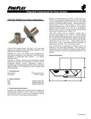
<strong>ICAF</strong> - Integrated Compressed Air Foam <strong>System</strong>Controls SectionPage 1 of 8User InterfaceAlpha-Numeric DisplaySection visiblethroughthe door window<strong>System</strong> LEDIndicatorsAC PowerAudiblesSilenceGround FaultPartialDisableReleaseDischargeAcknowledgeAlarm Silence/ Activate<strong>System</strong>ResetAlarmSupervisoryTrouble<strong>System</strong> Status LEDsand Operation KeysFunctionKeysF1F2F3InspectionLogNot Used<strong>System</strong>Shut-offLogActivatedDischargeSuspendedShut-Off KeyActivatedLeftRightMenu / ExitUp / PreviousDown / NextEnterMenuNavigation KeysFM-072C-0-275 AContrast Adjustment1. <strong>System</strong> Status LampsAlarm, Trouble and Supervisory lamps will flash for theirrespective events until acknowledged, at which point thelamp will illuminate steadily. The local Alphanumeric Displaywill provide additional details for every event (refer to screendetails in the text).- "AC POWER": A green lamp that illuminates steadily toindicate the presence of AC power and flashes whensystem is on battery power only.- "AUDIBLES SILENCE": A yellow lamp that illuminatessteadily when the ALARM SILENCE switch has beendepressed after an alarm. Lamp will begin flashing uponsubsequent alarm.- "GROUND FAULT": A yellow lamp that illuminates steadilyduring a ground fault condition.- "PARTIAL DISABLE": A yellow lamp that illuminatessteadily when any input or output circuit is disabled by theuser.- "RELEASE": A red lamp that illuminates steadily whensolenoid(s) is (are) activated and <strong>release</strong> occurs. Thislamp will flash when discharge is stopped (cycling typesystems only).- "DISCHARGE": A red lamp that illuminates steadily whenthe actual water flow has occurred.- "ALARM": Red lamp that flashes when an alarm occursand be<strong>com</strong>es steady after event have been acknowledged.- "SUPERVISORY": A yellow lamp that flashes uponactivation of a supervisory device (such as a tamper switchand air pressure switch or sensor) and be<strong>com</strong>es steadyafter event have been acknowledged.- "TROUBLE": A yellow lamp that flashes for any troublecondition and be<strong>com</strong>es steady after event have beenacknowledged. <strong>System</strong> internal routines trouble willactivate the trouble signals continuously.- "OPTION LAMPS": The three (3) option lamps (factorydefinedand identified Led1, Led2 & Led3) are used forvarious special functions.Contrast Adjustment: A small potentiometer is provided onthe circuit board to adjust the LCD contrast level. Thispotentiometer (shown above) can be accessed from thebottom of the LCD module when the cabinet door is openand adjusted <strong>with</strong> a small flat screwdriver.FM-0723-0-17 B
Page 2 of 8<strong>ICAF</strong> - Integrated Compressed Air Foam <strong>System</strong>Controls Section2. Keyboard - <strong>System</strong> Main Control KeysPanel is provided <strong>with</strong> a membrane type keyboard as shownon the previous page. Local sounder will beep once everytime a valid control key is depressed. Sounder will beeptwice anytime an invalid entry is made or user is scrolling toofast <strong>with</strong> the navigation keys. Various system main controlkeys are described below:ACKNOWLEDGE: Every new event must beacknowledged. Depressing this key will acknowledgealarms, supervisory and troubles while in their respectiveevents screen. The panel has alarm and trouble resound<strong>with</strong> lamp flash on subsequent events <strong>with</strong> alphanumericannunciation. The flashing lamp turns steady and the localsounder is silenced once all events have beenacknowledged.As shown above, before any event is acknowledged, theAlphanumeric Display shows the three letter code 'NAK' infront of the event description. Once acknowledged by theuser, this code changes to 'ACK'.By default, each event has to be acknowledgedindependently. The user can define in the TECHNICALSETUP - PARAMETERS menu that holding the key for 2seconds will acknowledge all the current category of eventsat once. When this feature is enabled, a second beep willconfirm the <strong>com</strong>mand has been executed and all events willdisplay the code 'ACK'.ALARM SILENCE / ACTIVATE: When alarms aresounding, pressing once on this key will turn off allthe audible devices connected to the silenceable NotificationAppliance Circuits (but not the Releasing Circuits). TheAUDIBLES SILENCE lamp will illuminate.When alarms are not sounding, pressing and holding the keyfor 2 seconds will activate the Alarm Condition, theNotification Appliance Circuits and the <strong>System</strong> Alarm Relaysbut not the Releasing Circuit(s). The ALARM ACTIVATEfunction of the key is always available and both functions arelatching, so will require a SYSTEM RESET to clear.SYSTEM RESET: The SYSTEM RESET key willonly operate while the system is either displaying anormal operating screen for lamp test or once all events inthe <strong>System</strong> Event Screens have been acknowledged. Tryingto reset the system while any event is still not acknowledgedwill silence the system buzzer momentarily, then make itbeep twice and finally continuously again. Once all eventsare duly acknowledged, a full reset sequence should takeonly a few seconds to <strong>com</strong>plete.Under normal conditions, pressing on the SYSTEM RESETkey make the local sounder beep once and will also performa LAMP TEST function.Under alarm, supervisory or trouble conditions, once allevents have been acknowledged and cleared, pressing onceon this key resets the system and breaks power to allinitiating device circuits, 4-wire smoke power and optionboards. It will also clear any activated output circuits.Should any alarm or trouble still exists after the reset, theywill automatically re-activate the panel (subsequent alarmfunction).3. Keyboard - Menu Navigation KeysUP / PREVIOUS: Pressing on this key once will scrollup the highlight to the PREVIOUS line on theAlphanumeric Display or increase the value of a digit.Pressing and holding the key will scroll fast up through thevalues of a digit.DOWN / NEXT: Pressing on this key once will scrolldown the highlight through the NEXT line on theAlphanumeric Display or decrease the value of a digit.Pressing and holding the key will scroll fast down through thevalues of a digit.LEFT ARROW: Pressing on this key once will scrollthe cursor (underscore) sideways to highlight thePREVIOUS digit or field on the Alphanumeric Display.RIGHT ARROW: Pressing on this key once will scrollthe cursor (underscore) sideways to highlight theNEXT digit or field on the Alphanumeric Display.Every time a valid navigation key is depressed, the localsounder will beep once. Holding the UP or DOWN keydepressed for 2 seconds will return the cursor (highlight onthe active item) directly up to the first or last item or field ofany list, depending on the key selected.The UP or DOWN keys will also scroll up or down a full pagein a list of items, thus accelerating navigation when used thesame way.Depressing the same key again when already at thebeginning or the end of a list will make the local sounderbeep twice to indicate an invalid entry. Any invalid entry willalso make the sounder beep twice.ENTER: This key is used to make and confirmchoices in the various user menus. It is also used tovalidate an entry or select an option.While <strong>with</strong>in the <strong>System</strong> Normal or <strong>System</strong> Event screens,pressing and holding the ENTER key for 2 seconds will giveaccess to specific system data screens.First screen displays the SENSORS LIST / TEMPERATUREas shown below, where up to 6 sensors pressures can bedisplayed. The cursor also highlights the screen name beingaccessed in the first line as shown below:FM-0723-0-17 B
<strong>ICAF</strong> - Integrated Compressed Air Foam <strong>System</strong>Controls SectionPage 3 of 8Fault condition for troubleshooting purposes. Refer toTROUBLESHOOTING section for additional details.In the TIMER STATUS screen, all the set values of thevarious timers are displayed as shown in the example below(actual screen may differ depending on systemconfiguration):<strong>System</strong> Temperature is displayed in the lower part of thisscreen. Trouble signal will be activated on high or lowtemperature indications (levels are factory defined). Thisvalue is used for system performance analysis and shouldnot be used as a thermometer.While in this screen, pressing on the RIGHT or LEFT keyswill scroll to display the BATTERY INFO. / GROUND FAULTstatus screen or the TIMER STATUS screen as shownbelow.In the BATTERY INFO screen the upper portion of thescreen displays the actual battery voltage, current and size.A minus sign in the Battery Current indication shows batteryload when the system is powered by the batteries:- BATTERY SIZE is displaying the value entered initially atthe factory or by the user. Refer to MENUS – BASICSETUP for additional details. CHARGING MODE is alsodisplayed in this section as per the current status ofbatteries:- TRICKLE indicates a fully loaded battery on low chargemode.- CHARGING indicates a low battery condition on highcharge mode and will also display a timer showing howlong the condition has been active.- DISABLE is displayed whenever the charger is turned off.This condition appears when system is in alarm state,when a battery fault has occurred or when AC power is off.- TEST indicates that the batteries are in the system'sAutomatic Battery Test mode (after a cold start or 30 daysafter last test). This mode also displays a timer showinghow long the condition has been active. If a bad conditionof battery is detected, system will go on trouble condition.The bottom section's GROUND FAULT STATUS indication isfor technician use and displays factory codes on GroundPressing on the MENU/EXIT key will exit the displayaltogether and return to the default screen.Note: Next time the user will access this display, system willautomatically return to the last screen it was displayingbefore exiting, making a quick return to the same datamuch easier.MENU / EXIT: Pressing and holding this key for 2seconds activates the user menu screen on theAlphanumeric Display and when pressed once <strong>with</strong>ina menu item, is used to exit from this menu item. To exitfrom the menu entirely, press and hold the key for 2 seconds.Typically, the display will automatically return to its defaultmode if no key activity is detected for a period of about 5minutes.Once modifications have been done in a menu section,exiting the menu will save all the new data for the entiresection in the system's memory. Individual items don't needto be saved individually.4. Keyboard - Function KeysThese three keys are configured forF1 F2 F3 special functions adapted to the <strong>ICAF</strong>system mode, but their programming isnot accessible to the user and is made at the factory. Thekeys functions are only available to the user when in theNormal Screen and while navigating through the <strong>System</strong>Events Screen.Note: The keys usage is also contextual – depending on themenu or utility, they can be used to perform other systemsrelated functions.- F1: INSPECTION LOG is used in conjunction <strong>with</strong> theARC-1 PC Interface software. It is used at the factory fortesting <strong>com</strong>plex sequence of operations <strong>with</strong> the help of aPC connected to the system, by setting up a flag in thesequence of operation. Once the sequence of operation isactivated, the PC will display all the events that occurredbetween the activation and the de-activation of this flag,making <strong>com</strong>plex sequences verification easier. The logcan also be printed for archiving.FM-0723-0-17 B
Page 4 of 8<strong>ICAF</strong> - Integrated Compressed Air Foam <strong>System</strong>Controls SectionPressing on the key will illuminate the LOG ACTIVATEDLED adjacent to the switch.- F2: Not used.- F3: SYSTEM SHUT-OFF is a special function associated<strong>with</strong> <strong>ICAF</strong> Extinguishing systems. Pressing on thisfunction key anytime during the discharge sequence andthen manually closing the water main supply control valvewill <strong>com</strong>pletely stop the flow of the foam agent. TheSHUT-OFF KEY ACTIVATED LED adjacent to the switchwill be illuminated while the function is active.Typically, to activate any function press and hold the key for2 seconds. Press and hold the key again to return to itsnormal status. Key status will also be indicated on the alphanumericdisplay bottom section as described earlier.5. Local Alphanumeric DisplayThe ARC-1 ® Analog Release Controller is provided <strong>with</strong> alocal Alphanumeric Display, Model LAA, mounted on thefront door that provides detailed indications for status display,operation and programming of the system. It is provided <strong>with</strong>a soft membrane keyboard accessible by opening the frontkey locked door. The alphanumeric display and the mainindicating lamps are visible through the door window at alltimes.Upon initial power up, the local sounder will be heard for 2seconds then will automatically stop. At the same time, theAlphanumeric Display will be<strong>com</strong>e momentarily blank andthen will show a scrolling "<strong>System</strong> Reset" indication. It willalso momentarily display the "P&P in Progress" indicationwhile the system's Plug and Play routine is executed.Note: The Plug & Play routine is automatically verifyingsystem integrity and module placement at both the initialstart-up and system reset.The start-up procedure should last only a few seconds, afterwhich, if the system is back under normal condition, theAlphanumeric Display will show the <strong>System</strong> Normal screen,similar to the one shown below:Note: Should the start-up routine take more than 2 minutesand system seems to be hung, perform a cold reset byremoving power to the unit and back. If problemcontinues, contact your nearest FireFlex AuthorizedDistributor.This screen displays the system configuration descriptionsuch as Fixed Discharge <strong>System</strong> in the example above andthe system status in a black window.The black bottom line typically shows current date and timeon the left and right respectively. In the center, the FunctionKeys status indicator code displays status of an activatedfunction for the corresponding key: A "1" indicates a functionis activated by Function Key F1, a "2" for F2 and a "3" for F3.No change or a "0" indicates that the function key(s) is(are)normal or not, assigned to any special function. Refer toparagraph 4 for additional details.Depending on the specific menu screen, an alternate bottomblack line shows number of alarms, supervisory and troubleevents, followed by the current date and time when an eventis present.Note: All the Alphanumeric Display screens shownthroughout this manual are typical and for generalinformation only. Actual screen details may varydepending on selected configuration and conditions.Time and date on initial start-up will show default values andwill have to be adjusted by the user (see MENUS – ACCESSLEVEL 2 for detailed instructions). Furthermore, time anddate will return to the last event values in memory every timethe system power is <strong>com</strong>pletely removed (both AC andbattery stand-by).Upon any event, the <strong>System</strong> Normal screen will change tothe <strong>System</strong> Event screen and show all current events andtheir status.Shown below is a flow chart describing in which order thesystem keys must be operated in case of various events:SINGLE EVENT OPERATION:NEW EVENT ACKNOWLEDGE RESETMULTI EVENTS OPERATION:EVENTS:ALARMSUPERVISORYTROUBLEACKNOWLEDGEALARM(S)ACKNOWLEDGESUPERVISORY(S)ACKNOWLEDGETROUBLE(S)(only after all eventshave been processed)RESET(only after all eventshave been processed)Here is a simulated <strong>System</strong> Event screen illustrating thevarious displays:FM-0723-0-17 B
<strong>ICAF</strong> - Integrated Compressed Air Foam <strong>System</strong>Controls SectionPage 5 of 8CIR.ID displays a 5 digit code used by the factory, describingmodule placement, circuit type, zone number and type ofactivation. Refer to TROUBLESHOOTING in Appendix Dfor additional details on these codes.DATE displays the date and time stamp at which thehighlighted event occurred.Note: Alarms have priority and will always override any otherevent. The alarm screen will always display first and overany other screen that might be displayed at the time of thealarm.The first line in the screen gives the number of events percategory in the following priority: Alarm, Supervisory andTrouble. Scrolling through the three categories is done usingthe following keys:Pressing on the RIGHT ARROW key will move thehighlight to the next category of events at the right, ie:from Alarm to Supervisory or from Supervisory toTrouble. When doing so, events of the highlighted categorywill be listed below.Pressing on the LEFT ARROW key will move thehighlight to the previous category of events at the left,i.e.: from Trouble to Supervisory or from Supervisoryto Alarm. When doing so, events of the highlightedcategory will be listed below.Note: The same function is applicable whenever the first lineof the display shows a few choices <strong>with</strong> one highlighted asshown in the figure above.Current events are displayed in the list, identified as 'NAK' forNot Acknowledged, or 'ACK' for Acknowledged, the firstevent remaining highlighted until acknowledged. Up to 99events are displayed per screen – (for the full list of events,use the EVENTS LOG). Note the cursor at the right side ofthe screen. The position of the black square indicates howfar in the list the display has gone.Next is the technical section, displaying various data for thehighlighted event:TYPE is a three letter code displaying which type of event ishighlighted where:ALM = AlarmTBL = TroubleSUP = SupervisoryNOP = Not Operated.OCCUR displays the number of occurrences of the event,which is particularly useful in case of intermittent events tosee how many times the event occurred. Total number ofoccurrences displayed in the even log is factory limited:- Alarms: 5- Supervisory: 4- Troubles: 3STATUS shows the actual status of the circuit where:ACT = ActiveNRM = Normal.ENABLE indicates if the circuit is Enabled (yes) or Disabled(no).<strong>System</strong> Sequence of OperationIMPORTANT NOTICE ! The detailed sequence of operationdescribed below is specifically written for your application.Other system's operation may differ greatly depending onthe system's requirements and particulars of the projects.Always refer to the Sequence of Operation provided <strong>with</strong>your unit for precise information.The heat detectors are wired on two zones for operation incrossed zones mode.The activation of EITHER detection zones will cause thefollowing:On the Control Panel Annunciator:- the zone in alarm will be displayed.- the ALARM LED will flash- the local buzzer will sound.<strong>System</strong> Output Activation:- an ALARM contact for the ALARM transmission to theMain Fire Alarm Building panel will be activated.- an ALARM signalling circuit will be activated.The activation of BOTH detection zones (crossed zones)will cause the following:On the Control Panel Annunciator:- the zones in alarm will be displayed.- the ALARM LED will flash- the local buzzer will sound.- the Release LED will illuminate- the Discharge LED will illuminate<strong>System</strong> Output Activation:- an ALARM contact for the ALARM transmission to theMain Fire Alarm Building panel will be activated.- an ALARM signalling circuit will be activated.- the <strong>release</strong> circuit will be activated and the CAFdischarge will occur.- the DISCHARGE contact will be activated for auxiliaryfunction.The activation of electrical emergency manual <strong>release</strong>station will cause the following:On the Control Panel Annunciator:- the zone in alarm (MANUAL PULL) will be displayed.- the ALARM LED will flash- the local buzzer will sound.- the Release LED will illuminate.- the Discharge LED will illuminateFM-0723-0-17 B
Page 6 of 8<strong>ICAF</strong> - Integrated Compressed Air Foam <strong>System</strong>Controls Section<strong>System</strong> Output Activation:- an ALARM contact for the ALARM transmission to theMain Fire Alarm Building panel will be activated.- an ALARM signalling circuit will be activated.- The <strong>release</strong> circuit will be activated and the CAFdischarge will occur.- The DISCHARGE contact will be activated for auxiliaryfunction.The activation of mechanical emergency manual stationinside the <strong>ICAF</strong> cabinet will cause the following:On the Control Panel Annunciator:- the zone in alarm (WATERFLOW) will be displayed.- the ALARM LED will flash- the local buzzer will sound.- the Discharge LED will illuminate<strong>System</strong> Output Activation:- an ALARM contact for the ALARM transmission to theMain Fire Alarm Building panel will be activated.- an ALARM signalling circuit will be activated.- the CAF discharge will occur and the DISCHARGEcontact will be activated for auxiliary function.Automatic DischargeNote: BEFORE CLOSING A VALVE OR ACTIVATING ANALARM, ADVISE THE SECURITY GUARD AND THECENTRAL SUPERVISORY STATION. THIS IS TOAVOID DISPATCHING THE FIRE DEPARTMENT INCASE OF A FALSE ALARM.Inspection LogThe function key F1 labelled "Inspection Log" is used inconjunction <strong>with</strong> the ARC-1 Remote Interface software forPC.The CAF discharge will occur for 10 minutes. At the end ofthe soak timer, the CAF discharge will automatically stop.The Release LED will then start flashing.Emergency discharge Shut-OffBecause the <strong>ICAF</strong> <strong>System</strong> cannot be turned off by theoperation of a single valve as is the case for a standardsprinkler system, a manual shut-off function is provided. TheCAF discharge can be manually suspended using thefollowing sequence of operation:1. Press and hold the function key F3 labelled: "<strong>System</strong>Shut-Off" on the keypad of the ARC-1 panel until itsadjacent red lamp is turned On.2. Close the system main water supply valve inside the<strong>ICAF</strong> cabinet. The red lamp labelled "Dischargesuspended" will turn On.Note: Mechanical emergency <strong>release</strong> valve must be innormal position prior the CAF discharge shut-off.IMPORTANT: After a fire, make sure it is <strong>com</strong>pletelyextinguished. If necessary, place a fire patrol in thezone covered by the system. Foam systems that havebeen subjected to fire must be returned to service assoon as possible. The entire system must be inspectedfor damage, and repaired or replaced as necessary.Warning! DO NOT CLOSE THE WATER SUPPLY TOMAKE REPAIRS WITHOUT PLACING A FIRE PATROLIN THE AREA COVERED BY THE SYSTEM. THEPATROL SHALL REMAIN THERE UNTIL THE SYSTEMIS BACK IN OPERATION. Advise local authorities of thenecessary work over the fire protection equipment.Follow emergency procedures required by codes and theAuthority Having Jurisdiction during system maintenance.FM-0723-0-17 B
<strong>ICAF</strong> - Integrated Compressed Air Foam <strong>System</strong>Controls SectionPage 7 of 8<strong>System</strong> Wiring DetailsThe following is a detail of the modules provided <strong>with</strong> thissystem and their placement location followed by the wiringdiagrams of each of these modules.<strong>ICAF</strong> <strong>System</strong> Modules Placement Detail:Power Supply & BatteryCharger ModulesAC Power SupplyTerminalsTransducersModulesReleasing PanelControl ModulesInput / OutputModulesPSATIABlankSCAGIA SSA SIASOA ARA BlankBlankBlankBlank12TBA34BCA1117772Y Y228883R94 9 R3394410101055511111166612 1212N.U.N.U.N.U.172839410511612N.U.1728394105 11612N.U.TBBBattery RacksGrounding BarFactory WiredTBB ModuleSSA Module – <strong>System</strong> Supervisory Circuits:FM-0723-0-17 B
Page 8 of 8<strong>ICAF</strong> - Integrated Compressed Air Foam <strong>System</strong>Controls SectionTIA Module – Pressure Transducers Interface:SIA Module – Supervised Input Zones:TYPICAL CLASS 'B' / STYLE 'B' ZONESFACTORY WIRINGFACTORY WIRINGSOA Module – Supervised Output Circuits:TYPICAL CLASS 'B' / STYLE 'Z' CIRCUITSTBA Factory Wiring Terminal Strip:INPUT POWER SOURCEFACTORY WIRINGTBB Factory Wiring Terminal Strip:ARA Module – Auxiliary Relay Outputs:FACTORY WIRINGFM-0723-0-17 B
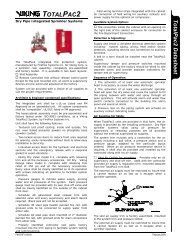
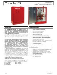
<strong>ICAF</strong> - Integrated Compressed Air Foam <strong>System</strong><strong>System</strong> Trim SectionPage 1 of 4<strong>ICAF</strong> <strong>System</strong> <strong>with</strong> Pneumatic Release1. DescriptionThe <strong>ICAF</strong> <strong>System</strong> utilizes a Flow Control valve (B14) tocontrol water flow into system piping equipped <strong>with</strong> openrotating spray nozzles. The system piping remains emptyuntil the <strong>pneumatic</strong> control line is activated by the operationof the <strong>pneumatic</strong> <strong>release</strong> system.Pneumatically controlled <strong>ICAF</strong> systems require a <strong>pneumatic</strong><strong>release</strong> system, equipped <strong>with</strong> fixed temperature <strong>release</strong>sand/or pilot heads. Release trim, for <strong>pneumatic</strong>ally controlled<strong>ICAF</strong> systems utilize a Pneumatic Actuator (R5) normallyheld closed by pressure maintained in the <strong>pneumatic</strong> <strong>release</strong>system.<strong>ICAF</strong> systems are designed so the system will open when adetector on the <strong>pneumatic</strong> <strong>release</strong> system operates. Whenthe <strong>pneumatic</strong> actuator (R5) opens, the <strong>pneumatic</strong> controlline is pressurized causing the water, air and foam<strong>pneumatic</strong>ally operated control valves (A1, B9 & F1) to opensimultaneously and generate the CAF into the dischargedevices and to be discharged over the area served by thedischarge devices.Note:The air supply for the <strong>pneumatic</strong> <strong>release</strong> piping system isprovided by the cylinder bank installed as part of the <strong>ICAF</strong><strong>System</strong> unit. It is re<strong>com</strong>mended to provide Inspectors TestConnections on the <strong>release</strong> system.Under normal conditions, system water supply pressureenters the priming chamber of the Flow Control Valve (B14)through the priming line which includes a normally openpriming valve (B1), strainer (B2), restricted orifice (B3) andspring loaded check valve (B4).1. <strong>System</strong> air supply pressurizes the normally closed air<strong>pneumatic</strong>ally operated control valve (A1), and the normallyclosed foam <strong>pneumatic</strong>ally operated control valve (F1).2. Water supply pressure is trapped in the primingchamber by a spring loaded check valve (B4) and thenormally closed water <strong>pneumatic</strong>ally actuated control valveValve (B9). The pressure in the priming chamber holds theFlow Control Valve (B14) clapper closed, keeping the outletchamber and system piping dry.3. <strong>System</strong> air supply pressurizes the normally closed air<strong>pneumatic</strong>ally actuated control valve (A1), the normallyclosed foam <strong>pneumatic</strong>ally actuated control valve (F1) andthe normally closed Solenoid Valve (R4) prevents the air tofill up the control lines, keeping the system closed.REFER TO NEXT PAGE TO VIEW TRIM SCHEMATIC.2. Normal conditionMain Water Supply Control Valve (D1) should be CLOSED.Priming valve (B1) must be CLOSED. Air supply must beCLOSED (see AIR SUPPLY SECTION). Flow TestValve (B6) and main drain valve (D3) must be CLOSED.Alarm test valve (B5) must be CLOSED. Verify that theEmergency Release valve (B10) is CLOSED. <strong>System</strong>flushing valve (A3) and foam injector flushing valve (F5) mustboth be CLOSED. All gauges (B11, B12 and E3) shouldshow 0 psi pressure.Foam concentrate tank (T1) must be filled according to theprocedure described in the FOAM SUPPLY section.Table 1: Pressure SettingsDEVICERelease <strong>System</strong> AirPressure Gauge (E3)Pneumatic ActuatorPressure Gauge (F4)Low Air SupervisoryPressure Switch (E4)WATER SUPPLY PRESSURESUp to 175 psi 175 psi (1 207 kPa)(1 207 kPa) to 250 psi (1724 kPa)35 PSI (241 kPa) 55 PSI (380 kPa)35 PSI (241 kPa) 55 PSI (380 kPa)25 PSI (173 kPa) 45 PSI (311 kPa)FM-0723-0-11 A
Page 2 of 4Trim Schematic:<strong>ICAF</strong> - Integrated Compressed Air Foam <strong>System</strong><strong>System</strong> <strong>with</strong> <strong>pneumatic</strong> <strong>release</strong><strong>System</strong> Trim SectionFM-0723-0-11 A
<strong>ICAF</strong> - Integrated Compressed Air Foam <strong>System</strong><strong>System</strong> Trim SectionPage 3 of 4Trim Components:A. AIR SUPPLY:A1 Air <strong>pneumatic</strong>ally operated control valve (N.C.)A2 Safety valveA3 <strong>System</strong> flushing valveA4 Air supply pressure gauge & valveA5 Clapper check valveB. WATER SUPPLY:B1 Priming valveB2 'Y' StrainerB3 ⅛" Restricted orificeB4 Spring loaded check valveB5 Alarm test valveB6 Flow test valveB7 Drip check valveB8 Drain check valveB9 Water <strong>pneumatic</strong>ally actuated control valve (N.C.)B10 Water supply control valveB11 Priming pressure water gauge & valveB12 Water supply presure gauge & valveB13 Clapper check valveB14 Flow control valveB15 Alarm pressure switchB16 Main drain valveC. CAF MIXING CHAMBER:C1 Mixing chamberC2 Foam injectorC3 Air injectorC4 Water injectorR. RELEASE SYSTEM:R1 Emergency <strong>release</strong> valveR2 3-Way N.C. 24Vdc solenoid valve (actuation)R3 N/AR4 N/AR5 Pneumatic actuator #1R6 Pneumatic actuator #2R7 ½" Supervised ball valveR8116" Restricted orificeR9 ¼" Ball valveR10 Pilot line pressure gaugeR11 Pilot line pressure supervisory switchR12116" Restricted orificeR13 ¼" Vent ball valveF. FOAM SUPPLY:F1 Foam <strong>pneumatic</strong>ally actuated control valve (N.C.)F2 Foam injection line 'Y' strainerF3 Spring loaded check valveF4 Foam injection line pressure gaugeF5 Foam injector flushing valveFM-0723-0-11 A
Page 4 of 4<strong>ICAF</strong> - Integrated Compressed Air Foam <strong>System</strong><strong>System</strong> Trim SectionFM-0723-0-11 A
<strong>ICAF</strong> - Integrated Compressed Air Foam <strong>System</strong>Air Supply SectionPage 1 of 4Air Supply SectionCompressed Air Foam is <strong>com</strong>posed of 90% <strong>com</strong>pressed air.This air is provided by DOT and TC certified <strong>com</strong>pressed aircylinders (C2) pressurized to 2,400 psi (16,536 kPa). Eachcylinder is supplied <strong>with</strong> a cylinder valve (C4) equipped <strong>with</strong> asafety relief disc (C3), which provides relief at 3600-4000 psi.Factory adjusted air pressure regulators (C5) are used toreduce the storage air pressure to a working pressure of100 psi (689 kPa) for the system operation.The cylinders bank pressure is supervised by a pressuretransducer (C7) that sends a low pressure supervisory signalwhen storage pressure goes under 2200 psi (15,158 kPa).That pressure represents the minimum pressure required toprovide air supply for the specified system discharge time.A safety valve (A2 - mounted in the cabinet) is also used atthe outlet of the air pressure regulator (C5) to protect thesystem from high pressure in case of malfunction. Theworking air pressure on the system side (downstream of theair regulator) is adjusted to a maximum of 150 psi(1034 kPa).The cylinders bank is factory assembled on a painted steelskid and includes the cylinders, support brackets, valves,high pressure tubing, discharge manifold (C8) and all thenecessary hardware.Cylinder Valve Guards (not shown) are used instead ofcylinder caps, eliminating the repetitive costs associated <strong>with</strong>the use of cylinder caps. These guards protects the cylinderheads during shipment, therefore no protective caps have tobe removed and most importantly, no tubing or fittings arerequired to be installed after receiving.The cylinders bank is also provided <strong>with</strong> a refilling outlet (C9),which allows refilling the <strong>com</strong>plete bank on-site <strong>with</strong> a highpressure <strong>com</strong>pressor, <strong>with</strong>out having to remove any otherparts or having to transport the cylinders to a filling plant.The skid mounted cylinders bank is available <strong>with</strong> single ortwin pressure regulator (C5) assemblies and is available inthe following storage capacities: up to 4 cylinders up to 8 cylinders up to 6 cylinders up to 10 cylinders up to 12 cylinders1. Air supply design and selection:The number of cylinders (C2) and regulators (C5) establishedat the design stage is based on both the maximum systemflow and discharge time required for the largest single hazardprotected or group of hazards that are protectedsimultaneously. FireFlex's program will take that intoaccount when calculating the system's capacity.Note regarding air cylinders: The calculated number of<strong>com</strong>pressed air cylinders is based on a storagetemperature of 70 ° F (21 ° C), for a storage temperaturerange between 60 ° F and 80 ° F (15.5 ° C and 26.6 ° C). Anystorage temperature outside this range must be taken intoconsideration during system design phase.2. Interconnection Piping to <strong>ICAF</strong> <strong>System</strong>There is one interconnection line (item 4) provided on all aircylinders banks. This connection is used to supply<strong>com</strong>pressed air between the cylinders bank and the <strong>ICAF</strong><strong>System</strong>. Piping is factory prepared according to installationarrangement and is supplied <strong>with</strong> the system.Fig. 1 - Cylinders Bank dimensions & capacity:StorageCapacityDimensions(inches)Nbr of cyls. Width Length Height4 246 368 24 48 8210 601272FM-0723-0-12 B
Page 2 of 4<strong>ICAF</strong> - Integrated Compressed Air Foam <strong>System</strong>Air Supply Section3. Operation5. Maintenance and inspection:.1 To OPEN Air Supply:.a Before opening any cylinder valve, verify that thepiping between the cylinder bank and the <strong>ICAF</strong><strong>System</strong> is properly installed and secured..b Slowly open one cylinder valve (C4) and check forany leak between the cylinder valve, the manifoldand the <strong>ICAF</strong> <strong>System</strong> air supply line (circled item 4).If there is no leak, pressure will build up in themanifold and the piping..c Once pressure is stabilized, pressure gauge (C6)should indicate a minimum pressure of 2200 psi. andpressure transducer (C7) should indicate a normalstatus at the ARC-1 Release controller..d Air pressure gauge (A4) inside the <strong>ICAF</strong> <strong>System</strong>cabinet should indicate a pressure of 100 psi. Referto TRIM SCHEMATIC section..e Open all of the remaining cylinders..2 To CLOSE air supply:.a Close all cylinders valves (C4)..b Bleed system manifold and air supply line by openingsystem flushing valve (A3). Refer to TRIMSCHEMATIC section.4. Recharge cylinders:After a system discharge or when cylinder pressure is underthe minimum re<strong>com</strong>mended pressure, cylinders must berefilled <strong>with</strong> dry air to a storage pressure of 2400 psi @ 70 ° F(16,536 kPa @ 21 ° C). The following steps must be followedbefore sending the cylinders for refilling..a Close all cylinder valves (C4)..b Bleed system manifold and air supply line by openingsystem flushing valve (A3). Refer to TRIMSCHEMATIC section..c After all the pressure is removed, pressure gauge(C6) should indicate a pressure of 0 psi..d Remove pressure regulator assembly (C5) andpressure gauge (C6)..e Properly plug manifold outlet to prevent any dirt fromcontaminating manifold during transport.Regular inspections, tests, and maintenance should beperformed at intervals specified in this document to verify thatthe air supply is in good operating condition and that itfunctions as intended.Cylinder inspection:Storage air pressure shall be checked at least semi-annually.If the air cylinders bank shows a pressure under 2200 psi. itshall be refilled or replaced.Hydrostatic test:High-pressure cylinders used in <strong>ICAF</strong> systems shall not berecharged <strong>with</strong>out a hydrostatic test (and remarking) if morethan 5 years have elapsed from the date of the last test.Cylinders continuously in service <strong>with</strong>out discharging shall bepermitted to be retained in service for a maximum of 12 yearsfrom the date of the last hydrostatic test. At the end of 12years, they shall be discharged and retested before beingreturned to service.Cylinders continuously in service <strong>with</strong>out discharging shall begiven a <strong>com</strong>plete external visual inspection every 5 years ormore frequently if required. The visual inspection shall be inaccordance <strong>with</strong> Section 3 of CGA C-6, Standard for VisualInspection of Steel Compressed Gas Cylinders, except thatthe cylinders need not be emptied or stamped while underpressure. Inspections shall be made only by <strong>com</strong>petentpersonnel and the results recorded on both of the following:(1) A record tag permanently attached to each cylinder(2) A suitable inspection reportA <strong>com</strong>pleted copy of the inspection report shall be furnishedto the owner of the system or an authorized representative.These records shall be retained by the owner for the life ofthe system.Where external visual inspection indicates that the containerhas been damaged, additional strength tests shall berequired.NOTICE: Empty cylinders must be recharged by FireFlexor its trained authorized agent. Contact FireFlex AfterSales Support Department for information about thenearest authorized agent to your location.FM-0723-0-12 B
<strong>ICAF</strong> - Integrated Compressed Air Foam <strong>System</strong>Air Supply SectionPage 3 of 4Figure 2 – Compressed Air Cylinders Bank(Rack mounted)Air supply Components:C1Cylinders rackC5Pressure regulatorC2Compressed air cylinderC6Pressure gaugeC3Safety <strong>release</strong> diskC7Pressure transducerC4Cylinder valveC8High pressure manifoldC9Refilling outletFM-0723-0-12 B
Page 4 of 4<strong>ICAF</strong> - Integrated Compressed Air Foam <strong>System</strong>Air Supply SectionThis page is left blank intentionally.FM-0723-0-12 B
<strong>ICAF</strong> - Integrated Compressed Air Foam <strong>System</strong>Foam Supply SectionPage 1 of 6Foam Supply Section1. Foam Storage TankFoam concentrate is stored inside a stainless steel pressurevessel type tank (T1) stamped according to ASME SectionVIII Div. 1. Storage tank is normally unpressurized; maximumworking pressure is 150 psi (1033 kPa). The tank is supplied<strong>with</strong> a safety relief valve (T8) set at 135 psi (930 kPa) forprotection against over-pressurization.Foam storage tank is factory assembled and includes all thevalves, trim and hardware as shown on Figure 2. Manualvalves are provided to fill the tank (T9) <strong>with</strong> foam concentrateand to <strong>release</strong> the air pressure (T6) after a CAF discharge. Asight gauge (T5) is also provided to allow visual verification ofthe tank foam concentrate normal level.2. Foam ConcentrateCAF system shall be used <strong>with</strong> the following foamconcentrates and concentrations:Foam concentrateConcentrationHydrocarbonsNational Foam Aer-O-Lite 3% 2%National Foam Aer-O-Water 3EM 3% 2%Polar SolventsAnsul Ansulite 3X3 LV 6%Shelf LifeThe shelf life of any foam concentrate is maximized by properstorage conditions and maintenance. Factors affecting shelflife are wide temperature changes, extreme high or lowtemperatures, evaporation, dilution, and contamination byforeign materials. Properly stored foam concentrates havebeen tested and shown no significant loss of fire fightingperformance, even after 15 years. For further details, see theFoam Concentrate Data Sheet.Environmental and Toxicological InformationFoam concentrates used <strong>with</strong> Compressed Air Foam <strong>System</strong>sare biodegradable. However, as <strong>with</strong> any substance, careshould be taken to prevent discharge from entering groundsurface water, or storm drains. Since facilities vary widely bylocation, disposal should be made in accordance <strong>with</strong> federal,state and local regulations. For further details, see the foamConcentrate Data Sheet and Material Safety Data Sheet.3. Foam tank design and selectionThe capacity established at the design stage is based on boththe maximum system flow and discharge time required for thelargest single hazard protected or group of hazards that areprotected simultaneously; FireFlex's design software will takethat into account when calculating the system's capacity.Consequently, multiple foam tanks can be installed in parallelto satisfy project requirements.4. Interconnection Piping to <strong>ICAF</strong> <strong>System</strong>There are two interconnection lines provided on all foamstorage tanks. One connection is used to pressurize thefoam storage tank <strong>with</strong> <strong>com</strong>pressed air (circled item 3), theother to provide foam concentrate to the mixing chamber(circled item 2). Piping between the foam storage tank andthe <strong>ICAF</strong> <strong>System</strong> is factory prepared according to theinstallation arrangement and supplied <strong>with</strong> the system.Figure 1 - Storage tank dimensions & capacity:H8"ANominal Dimensions (in) Outlet (NPTF) ManholeCapacity USGal A D H B C E25 35 16 4335 23 24 31 1"50 33 24 41100 66 24 74N/A200 54 36 62 2" 1"300 67 38 75400 67 48 75450 78 48 86 3" flange16" X 12"500 65 54 73BCDEFM-0723-0-13 D
Page 2 of 6<strong>ICAF</strong> - Integrated Compressed Air Foam <strong>System</strong>Foam Supply Section5. OperationFoam storage tankThe storage tank (T1) contains foam concentrate underatmospheric pressure in normal conditions. Upon actuation ofthe system, the foam <strong>pneumatic</strong>ally activated control valve(F1) opens, pressurizing the storage tank <strong>with</strong> air andexpelling the foam concentrate in the foam injection linethrough a dip tube (F2). Foam concentrate is then injected inthe mixing chamber (C1) through a calibrated orifice (C2)sized to generate CAF in the correct proportions.Foam Tank Normal conditionsBefore placing the foam tank in service, verify that the pipingbetween the foam tank and the <strong>ICAF</strong> <strong>System</strong> is properlyinstalled and secured.1. Tank drain valve (T3) is locked CLOSED.2. Tank refill valve (T9) is locked CLOSED.3. Tank refill vent valve (T6) is locked CLOSED.4. Sight gauge isolation valves (T4) are locked CLOSED.5. Foam tank pressure gauge (T7) shows 0 psi (0 kPa)pressure.(Refer to Figure 1 for foam storage tank schematic)Sight gaugeThe sight gauge (T5) is a device used to provide visualindication of the foam concentrate level in the storage tank(T1) during the system periodic inspections. Sight gauge (T5)shall not show any reading during normal stand-by andoperating conditions since both its isolation valves (T4) shouldbe locked CLOSED.Level check procedure:(Refer to figure 2- Foam storage tank schematic).Normal inspection: Under normal standby conditions, foamstorage tank (T1) is not pressurized. Sight gauge (T5) shouldnot show any reading and tank pressure gauge (T7) shouldbe at 0 psi (0 kPa).1. Verify that foam storage tank pressure gauge (T7) shows0 psi (0 kPa) pressure.2. OPEN both sight gauge isolation valves (T4).3. SLOWLY OPEN tank refill vent valve (T6), allowing thefoam concentrate stored in the tank to reach its level inthe sight gauge tube.4. Check the sight gauge (T5) level:a) If level is normal, CLOSE the bottom sight gaugeisolation valve (T4) and drain concentrate from levelgauge tube by opening the tank drain valve (T3).Once the level gauge tube is drained, CLOSE tankdrain valve (T3), both sight gauge isolation valves(T4) and the tank refill vent valve (T6).b) If level is below normal, add foam concentrate upto normal level by following FILLING PROCEDUREdescribed in section 6.After a system dischargeFoam storage tank (T1) is pressurized when operated;therefore pressure must be relieved before a sight gauge(T5) reading can be taken after a discharge.1. To allow air to vent from the foam storage tank,SLOWLY AND PARTIALLY OPEN tank refill vent valve(T6) until tank pressure gauge (T7) indicates 0 psi (0kPa) pressure.2. OPEN both sight gauge isolation valves (T4).3. SLOWLY OPEN tank refill vent valve (T6). This willallow the remaining foam concentrate in the tank toreach its level in the sight gauge tube.4. Check sight gauge level (T5).a) If level is normal, CLOSE the bottom sight gaugeisolation valve (T4) and drain concentrate from levelgauge tube by opening the tank drain valve (T3).Once the level gauge tube is drained, CLOSE tankdrain valve (T3), both sight gauge isolation valves(T4) and the tank refill vent valve (T6).b) If level is below normal, add foam concentrate upto normal level by following FILLING PROCEDUREdescribed in section 6.6. Filling ProcedureNOTICE: USE ONLY FOAM CONCENTRATEAPPROVED FOR FIREFLEX'S COMPRESSED AIRFOAM SYSTEM.SAFETY NOTICE: Foam concentrates are primary eyeirritants, and contact <strong>with</strong> the eyes should be avoided.Users are advised to wear protective equipmentwhen filling foam tank. If foam concentrate enters theeyes, flush them well <strong>with</strong> water and seek immediatemedical attention. For further details, see foamconcentrate Material Safety Data Sheet.1. Before starting the fill procedure, insure that the foamstorage tank (T1) is not pressurized. Verify that foamstorage tank pressure gauge (T7) shows 0 psi (0 kPa)pressure.2. Verify that you have in hand the amount of foamconcentrate that corresponds to the storage tank ratedcapacity.3. Storage Tank Drain Valve (T3) and Level Sight GaugeIsolation Valves (T4) should be closed.4. Open the Foam Refill Valve (T9) and the Foam RefillVent Valve (T6).5. Prime and connect the concentrate pumping apparatusto the Foam Refill Valve (T9). Use a Hand-operatedDrum Pump, a Centrifugal Pump or Pneumatic OperatedDiaphragm Pump.FM-0723-0-13 C
<strong>ICAF</strong> - Integrated Compressed Air Foam <strong>System</strong>Foam Supply SectionPage 3 of 66. Slowly start to pump the concentrate into the storagetank and adjust the flow to avoid concentrate overflows atthe Foam Refill Vent Valve (T6).7. When approximately 90% of the nominal charge hasbeen pumped, stop pumping and open the level sightgauge isolation valves (T4) to check the sight gauge (T5)level.8. Resume pumping at a very slow rate and stop pumpingwhen level reaches about halfway in the sight gauge.9. CLOSE bottom sight gauge isolation valve (T4) and drainconcentrate from level gauge tube by opening tank drainvalve (T3).10. Once the level gauge tube is drained, CLOSE tank drainvalve (T3) and both sight gauge isolation valves (T4).11. CLOSE the Foam Refill Valve (T9) and the Foam RefillVent Valve (T6).7. Maintenance and inspectionsRegular inspections, tests, and maintenance should beperformed at intervals specified in this document to verify thatthe foam supply is in good operating condition and that itfunctions as intended. The system shall be so arranged thattests can be performed <strong>with</strong> as little loss of foam as practical.Components shall be restored to full operational conditionfollowing inspection and testing.Foam Tank Normal conditionsVerify that all valves are in the proper position (refer to page 2and the foam storage tank schematic).Foam concentrate level checkRegular inspections should be performed to verify theconcentrate level, follow the level check procedure describedon page 2. If the concentrate is lower than re<strong>com</strong>mended,refer to the refilling instructions on page 3.Foam sample analysisInspection of foam concentrates and their containers shall bemade for evidence of excessive sludging or deterioration.Inspection shall include a qualitative test of the foamconcentrate normally conducted by the manufacturer.Presence of specific quantities of concentrates in systemstorage equipment in service ready position and quantities ofreserve concentrates on hand shall be checked <strong>with</strong>requirements for same.Eight ounce (8 oz.) (250 ml) samples of foam concentrateshould be taken from the Storage tank drain valve (T3). Foamsamples may be sent to FireFlex <strong>System</strong>s.Either glass or plastic bottles are satisfactory, provided theyare leak-proof and well packaged. The sample(s) must belabelled and provide the location, type of concentrate, lotnumber and date, storage container, name and phonenumber of the person sending the sample(s). The sample(s)will be evaluated for appearance, foam expansion, drain time,and film spread, as <strong>com</strong>pared to foam standards.Foam sample collection procedure:(Refer to figure 2- Foam storage tank schematic)Under normal standby conditions, foam storage tank (T1) isnot pressurized. Sight gauge (T5) should not show anyreading and tank pressure gauge (T7) should be at 0 psi(0 kPa).1. Verify that foam storage tank pressure gauge (T7)shows 0 psi (0 kPa) pressure.2. OPEN both sight gauge isolation valves (T4).3. SLOWLY OPEN tank refill vent valve (T6), allowing thefoam concentrate stored in the tank to reach its level inthe sight gauge tube.4. Collect the sample of foam concentrate by openingstorage tank drain valve (T3).5. Once the sample is collected, close the storage tankdrain valve (T3).6. CLOSE bottom sight gauge isolation valve (T4) anddrain concentrate from level gauge tube by opening tankdrain valve (T3). Once the level gauge tube is drained,CLOSE tank drain valve (T3), both sight gauge isolationvalves (T4) and tank refill vent valve (T6).Foam injection line testing procedure(Refer to TRIM SCHEMATIC in the <strong>ICAF</strong> <strong>System</strong> section)Regular tests should be performed to verify that the foaminjection line is not clogged by any debris or coagulated foamconcentrate that would impair its proportioning rate.Under normal standby conditions, foam injection line is notpressurized. Foam injection line pressure gauge (F4) shouldread 0 psi (0 kPa).1. <strong>System</strong>'s air supply should be open; air pressure gauge(A4) inside the <strong>ICAF</strong> <strong>System</strong> cabinet should indicate apressure of 100 psi.2. OPEN foam injector flushing valve (F5).3. Wait approximately 5 seconds or until pressure stabilizesat the foam injection line pressure gauge (F4).4. CLOSE foam injector flushing valve (F5).5. Foam injection line pressure gauge (F4) should ventquickly and indicate 0 psi (0 kPa) after a few seconds.6. If the foam injection line doesn't vent properly, the foaminjector (C2) shall be disassembled, cleaned, andreassembled.FM-0723-0-13 D
Page 4 of 6<strong>ICAF</strong> - Integrated Compressed Air Foam <strong>System</strong>Foam Supply SectionFoam injection line post discharge testing procedure(Refer to TRIM SCHEMATIC in the <strong>ICAF</strong> <strong>System</strong> section)A test should be performed to verify that the foam injectionline is not clogged by any debris or coagulated foamconcentrate that would impair its proportioning rate.Under normal standby conditions, foam injection line is notpressurized. Foam injection line pressure gauge (F4) shouldread 0 psi (0 kPa).1. <strong>System</strong>'s air supply should be open; air pressure gauge(A4) inside the <strong>ICAF</strong> <strong>System</strong> cabinet should indicate apressure of 100 psi.2. OPEN foam injector flushing valve (F5).3. Wait approximately 1 minute or until pressure stabilizesat the Foam injection line pressure gauge (F4).4. CLOSE foam injector flushing valve (F5).5. Foam injection line pressure gauge (F4) should ventquickly and indicate 0 psi (0 kPa) after a few seconds.6. If the foam injection line doesn't vent properly, the foaminjector (C2) shall be disassembled, cleaned, andreassembled.Foam injection strainer maintenanceRemove, clean and replace foam injection line strainer (F2)screen in original position (Note: In some instances, a highpressure water jet or steam may be required for effectivecleaning) Inspect cover gasket for damage. Replace ifnecessary.Inspection Frequency Table<strong>System</strong>/ComponentFrequencyFoam tank normal conditionsMonthlyFoam concentrate level checkAnnuallyFoam sample analysisAnnuallyFoam injection line testQuarterlyFoam injection strainer maintenanceAnnuallyFM-0723-0-13 C
<strong>ICAF</strong> - Integrated Compressed Air Foam <strong>System</strong>Foam Supply SectionPage 5 of 6Figure 2 – Foam storage tank schematic:Foam storage tank <strong>com</strong>ponents:T1 Foam storage tankT2 Dip tubeT3 Storage tank drain valveT4 Level sight gauge isolation valveT5 Foam level sight gaugeT6 Foam refill vent valveT7 Pressure gaugeT8 Pressure safety valveT9 Foam refill valveFM-0723-0-13 D
Page 6 of 6<strong>ICAF</strong> - Integrated Compressed Air Foam <strong>System</strong>Foam Supply SectionThis page is left blank intentionally.FM-0723-0-13 D
<strong>ICAF</strong> - Integrated Compressed Air Foam <strong>System</strong><strong>System</strong> Characteristics SectionPage 1 of 4Cabinet for Self-Contained Unit(With Control Panel)The <strong>ICAF</strong> unit cabinet is made of sturdy 14 gauge steel,measuring 36" x 20" x 71" (91,4 x 50,8 x 180,3 cm) or 46" x24" x 71" (116,8 x 61 x 180,3 cm) depending on theconfiguration provided. Refer to Figure 1 for dimensions.All surfaces are rust proof coated, inside and outside, <strong>with</strong>fire red, oven baked polyester powder on phosphate base.Cabinet is provided <strong>with</strong> individual access doors for thehydraulic and electrical sections and the emergency <strong>release</strong><strong>with</strong> a neoprene gasket to avoid vibrations.Electrical junction boxes are integrated <strong>with</strong> the cabinet forconnection of detection system, auxiliary contacts andsignaling devices. Knockouts can be drilled by the installingcontractor on-site but have to meet the restrictions indicatedon Figure 2.Gauges to indicate air, water supply pressure and primingwater pressure are all visible through clear Lexan windows.IMPORTANT! <strong>ICAF</strong> units are NOT designed to beinstalled where they will be subjected to outdoors and/orfreezing conditions. Refer to ENVIRONMENTAL DATAfor additional details. Subjecting the unit to conditionsoutside these limitations might hamper the normaloperation of the system.Cabinet doors are provided <strong>with</strong> hinges that can easily bedisassembled on site to remove the door assemblies forservicing. The cabinet assembly is pre-assembled, prewired,and factory tested under ISO-9001 conditions.Note: The mechanical section of the <strong>ICAF</strong> and theelectrical section are provided in two separate enclosures,stacked one on top of the other.FM-0723-0-14 C
Page 2 of 4<strong>ICAF</strong> - Integrated Compressed Air Foam <strong>System</strong><strong>System</strong> Characteristics SectionFigure 1 – Dimensions:2" MAX.VOPTIONAL OUTLET(DRILLED ONLY WHEN2 nd MIXING CHAMBER IS REQUIREDSIZE VARIES ACCORDINGTO MIXING CHAMBER SIZEMIXING CHAMBER 2SCH.40 GROOVED OUTLETSIZE VARIES ACCORDINGTO MIXING CHAMBER SIZEENMIXING CHAMBER 1SCH.40 GROOVED OUTLETDRAIN - SCH.40 GROOVED OUTLETNBASLWMWATER INLETSCH.40 GROOVED OUTLETMKGHSee NoteDFJT9/16" DIA. (4 HOLES)TNote: Access holes provided onenclosure bottom plate to accessanchoring holes.TUA = WATER INLET DIAMETERB = DRAIN PIPE DIAMETERTFLOOR ANCHORING TEMPLATEUFM-08GC-0-1C.dwg<strong>System</strong>Size A B D E F G H J K L M N S T U V W¾" 2" 2" 36" 57" 20" 4" 8⅞" 9" 18½" 3½" 6" 2" 49½" 2¾" 4" 14" 39¼"1½" 2" 2" 36" 57" 20" 4" 8⅞" 9" 18½" 3½" 6" 2" 49½" 2¾" 4" 14" 39¼"2" 2" 2" 36" 57" 20" 4" 8⅞" 9" 18½" 3½" 6" 2" 49½" 2¾" 4" 14" 39¼"3" 4" 2" 36" 57" 20" 4" 9⅞" 9" 18½" 3½" 6" 2" 49½" 2¾" 4" 14" 39¼"Note: Dimension W and S are nominal and may vary by about ¼". Drain pipe shall be connected to an open drain.FM-0723-0-14 C
<strong>ICAF</strong> - Integrated Compressed Air Foam <strong>System</strong><strong>System</strong> Characteristics SectionPage 3 of 4Drilling Guide:When drilling in the cabinet to install wiring conduits or pipes,use only the shaded area shown below. Always avoid drillinginto internal <strong>com</strong>ponents.Figure 2 – Drilling detail:Wiring Routing:Wiring shown in Figure 3 below indicates typical WiringRouting for Power Limited Circuits.Refer to FIELD WIRING DIAGRAM and drilling guide abovefor details.IMPORTANT ! Drill holes in the two shadedareas only to avoid internal <strong>com</strong>ponents andabout 1/2" from cabinet rear edge as shown.5"15"3"FM-072C-0-251 B.dwg9"Figure 3 – Wiring routing:Power-limited Circuits wiringAC Power Supply WiringTypical Shielded wiringKnock-outs (drilled by contractor)PSATIA Blank SCA GIA SSA SIA SOA ARABlank Blank Blank BlankTBAYRYRBCATBBTBBFM-072C-0-254B.dwgFactory wiringFM-0723-0-14 C
Page 4 of 4<strong>ICAF</strong> - Integrated Compressed Air Foam <strong>System</strong><strong>System</strong> Characteristics SectionThis page is left blank intentionally.FM-0723-0-14 C
<strong>ICAF</strong> - Integrated Compressed Air Foam <strong>System</strong>Notes & WarrantyPage 1 of 2User NotesFM-0723-0-16 B
Page 2 of 2<strong>ICAF</strong> - Integrated Compressed Air Foam <strong>System</strong>Notes & WarrantyLimited WarrantyFireFlex <strong>System</strong>s inc. (known herein as "the Manufacturer")warrants to its customer that its products shall be free ofdefects in material [or part(s)] and workmanship for a periodof twelve (12) months from the date of original delivery, undernormal use and service by the Customer (and provided thatthe product has been properly installed and maintained).The obligation of the Manufacturer is case of a claim madeby the Customer hereunder, shall be, at the Manufacturer'soption, to repair or replace, free of charge for parts or labor,any product or part, which in the opinion of the Manufacturer,shall be proven to be defective.The present warranty shall be void should the product [orpart(s)] be altered by anyone other than the Manufacturer. Incase of a claim under the present warranty, the Customermust contact the Manufacturer's Customer ServiceDepartment as soon as he is aware of a claim and, subject tothe authorization of the manufacturer, return the defectiveproduct [or part(s)], transportation prepaid, to the addresslisted below.This warranty constitutes the entire warranty given by theManufacturer to the Customer <strong>with</strong> respect to the product.The present warranty is non-transferable and nonassignable.The Manufacturer does not represent that theproducts will prevent any loss by fire or otherwise or that theproduct will in all cases provide the protection for which it hasbeen installed or intended.The Customer acknowledges that the Manufacturer is not aninsurer. The manufacturer shall not be liable for any loss ordamages of any nature whatsoever, including but not limitedto incidental or special or consequential damages includingbut not limited to, property damages, personal injury, revenueloss or lost profits, inconveniences, transportation charges orother damages suffered by anyone.There are no other warranties, expressed or implied <strong>with</strong>regard to the products, other than those contained herein.Some jurisdictions may not allow limitations on how long anexpressed warranty lasts, so the above limitations may notapply to you. Under no circumstances, shall theManufacturer be liable for any loss of, or damage to property,direct or indirect, incidental or special or consequentialdamages, arising out of the use or inability to use theManufacturer's products.The Manufacturer shall not be liable for any personal injurywhich may arise in the course of or as a result of the use ofthe manufacturer's products.This warranty replaces all previous warranties and is the onlywarranty given by the Manufacturer <strong>with</strong> respect to itsproducts. This warranty shall not be modified, unless suchmodification is made in writing by an executive officer of theManufacturer.In consideration of the warranty provisions contained herein,the Customer hereby waives the benefit of any statutorywarranty or protection or remedy to which he may be entitledunder the terms of any sales of goods act or similarlegislation available to him in any jurisdiction in which theCustomer carries on business.Special Limitation: Due to their self dischargecharacteristics when not charged during extended storageperiods, batteries supplied <strong>with</strong> releasing control panels arecovered by the above warranty for a period limited to three(3) months only.Products Support1-866-347-3353When you bought this <strong>ICAF</strong> Integrated Compressed AirFoam <strong>System</strong> from FireFlex <strong>System</strong>s Inc., you got the besttechnology available… You also got the best people…People who make it easy and convenient for you to own ourproducts.Outstanding products support doesn't just mean helpingfixing products when they fail. When you need our help,knowledgeable professionals will give you fast, personalassistance.Our Products Support organization is dedicated to helpingyou be<strong>com</strong>e <strong>com</strong>fortable <strong>with</strong> FireFlex <strong>System</strong>s Inc. byanswering questions about our products, warranty andservice procedures and by helping you learn how to installand use our products more effectively.The number above is a toll free number to Products Support.Please save it and keep it for the day when you may have totest us.FireFlex <strong>System</strong>s inc.1935, Lionel-Bertrand Blvd.Boisbriand, QuebecCanada J7N 1N8Tel.: (450) 437-3473 - Fax: (450) 437-1930Toll Free: (866) 347-3353Web site: http://www.fireflex.<strong>com</strong>FM-0723-0-16 B