ICAF System with pneumatic release - Fireflex.com
ICAF System with pneumatic release - Fireflex.com
ICAF System with pneumatic release - Fireflex.com

You also want an ePaper? Increase the reach of your titles
YUMPU automatically turns print PDFs into web optimized ePapers that Google loves.
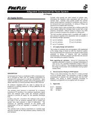
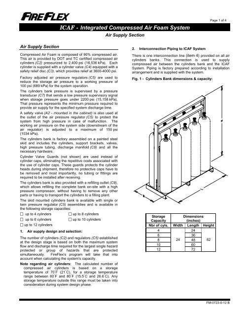
<strong>ICAF</strong> - Integrated Compressed Air Foam <strong>System</strong>Air Supply SectionPage 1 of 4Air Supply SectionCompressed Air Foam is <strong>com</strong>posed of 90% <strong>com</strong>pressed air.This air is provided by DOT and TC certified <strong>com</strong>pressed aircylinders (C2) pressurized to 2,400 psi (16,536 kPa). Eachcylinder is supplied <strong>with</strong> a cylinder valve (C4) equipped <strong>with</strong> asafety relief disc (C3), which provides relief at 3600-4000 psi.Factory adjusted air pressure regulators (C5) are used toreduce the storage air pressure to a working pressure of100 psi (689 kPa) for the system operation.The cylinders bank pressure is supervised by a pressuretransducer (C7) that sends a low pressure supervisory signalwhen storage pressure goes under 2200 psi (15,158 kPa).That pressure represents the minimum pressure required toprovide air supply for the specified system discharge time.A safety valve (A2 - mounted in the cabinet) is also used atthe outlet of the air pressure regulator (C5) to protect thesystem from high pressure in case of malfunction. Theworking air pressure on the system side (downstream of theair regulator) is adjusted to a maximum of 150 psi(1034 kPa).The cylinders bank is factory assembled on a painted steelskid and includes the cylinders, support brackets, valves,high pressure tubing, discharge manifold (C8) and all thenecessary hardware.Cylinder Valve Guards (not shown) are used instead ofcylinder caps, eliminating the repetitive costs associated <strong>with</strong>the use of cylinder caps. These guards protects the cylinderheads during shipment, therefore no protective caps have tobe removed and most importantly, no tubing or fittings arerequired to be installed after receiving.The cylinders bank is also provided <strong>with</strong> a refilling outlet (C9),which allows refilling the <strong>com</strong>plete bank on-site <strong>with</strong> a highpressure <strong>com</strong>pressor, <strong>with</strong>out having to remove any otherparts or having to transport the cylinders to a filling plant.The skid mounted cylinders bank is available <strong>with</strong> single ortwin pressure regulator (C5) assemblies and is available inthe following storage capacities: up to 4 cylinders up to 8 cylinders up to 6 cylinders up to 10 cylinders up to 12 cylinders1. Air supply design and selection:The number of cylinders (C2) and regulators (C5) establishedat the design stage is based on both the maximum systemflow and discharge time required for the largest single hazardprotected or group of hazards that are protectedsimultaneously. FireFlex's program will take that intoaccount when calculating the system's capacity.Note regarding air cylinders: The calculated number of<strong>com</strong>pressed air cylinders is based on a storagetemperature of 70 ° F (21 ° C), for a storage temperaturerange between 60 ° F and 80 ° F (15.5 ° C and 26.6 ° C). Anystorage temperature outside this range must be taken intoconsideration during system design phase.2. Interconnection Piping to <strong>ICAF</strong> <strong>System</strong>There is one interconnection line (item 4) provided on all aircylinders banks. This connection is used to supply<strong>com</strong>pressed air between the cylinders bank and the <strong>ICAF</strong><strong>System</strong>. Piping is factory prepared according to installationarrangement and is supplied <strong>with</strong> the system.Fig. 1 - Cylinders Bank dimensions & capacity:StorageCapacityDimensions(inches)Nbr of cyls. Width Length Height4 246 368 24 48 8210 601272FM-0723-0-12 B