A New Design for Audio Clipping Pre-amplifiers Based on ... - IJME
A New Design for Audio Clipping Pre-amplifiers Based on ... - IJME
A New Design for Audio Clipping Pre-amplifiers Based on ... - IJME
Create successful ePaper yourself
Turn your PDF publications into a flip-book with our unique Google optimized e-Paper software.
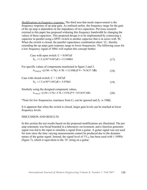
Modificati<strong>on</strong>s in frequency resp<strong>on</strong>se: The third area that needs improvement is thefrequency resp<strong>on</strong>se of op amp gain. As outlined earlier, the frequency range <str<strong>on</strong>g>for</str<strong>on</strong>g> the gainof the op amp is dependent <strong>on</strong> the impedance of two capacitors. <str<strong>on</strong>g>Pre</str<strong>on</strong>g>vious researchexternal to this paper has proposed widening this frequency bandwidth by changing thevalues of these capacitors. This proposed design is to be implemented by c<strong>on</strong>necting acapacitor in parallel using a SPST switch to another capacitor that is in series with ‘R I ’ .When the switch is closed, the parallel capacitance combinati<strong>on</strong> alters ‘Z I ’, therebyextending the op amps gain resp<strong>on</strong>se range to lower frequencies. The following cases <str<strong>on</strong>g>for</str<strong>on</strong>g>a low frequency signal of 30Hz will explain this c<strong>on</strong>cept further.Case with open switch: C = 0.047uFX C = 1/2π (30* 0.047µF) = 112.88KΩ(17)For specific values of comp<strong>on</strong>ents menti<strong>on</strong>ed in figure 2 and 3,A VMAX = [(1M+4.7K)/ 4.7K + 112.88K)]*9 = 76.9(37.7dB) (18)Case with closed switch: C = 1.047uFX C = 1/2π (30*1.047µF) = 5.07KΩ(19)Similarly using the designed comp<strong>on</strong>ent values,A VMAX = [(1M + 4.7K) / 4.7K + 5.07K)]*9 = 925.8(59.3dB)(20)*Note <str<strong>on</strong>g>for</str<strong>on</strong>g> low frequencies, reactance from C F can be ignored and Z F is 1MΩ.It is apparent that when the switch is closed, larger gain levels can be reached at lowerfrequency levels.DISCUSSION AND RESULTSIn this secti<strong>on</strong> the test results based <strong>on</strong> the proposed modificati<strong>on</strong>s are illustrated. The preamp schematic was bread boarded in a laboratory envir<strong>on</strong>ment, and a functi<strong>on</strong> generatorsignal was fed to the input to simulate a signal from a guitar. A guitar signal was not used<str<strong>on</strong>g>for</str<strong>on</strong>g> tests since the time varying measurements cannot be produced due to the dynamicnature of the guitar signal. Instead, the signal level of 1V AC has been used with 1.109Hz(figure 7), which is equivalent to the ‘D’ string <strong>on</strong> a guitar.Internati<strong>on</strong>al Journal of Modern Engineering Volume 8, Number 1 Fall 2007 120


