A New Design for Audio Clipping Pre-amplifiers Based on ... - IJME
A New Design for Audio Clipping Pre-amplifiers Based on ... - IJME
A New Design for Audio Clipping Pre-amplifiers Based on ... - IJME

Create successful ePaper yourself
Turn your PDF publications into a flip-book with our unique Google optimized e-Paper software.
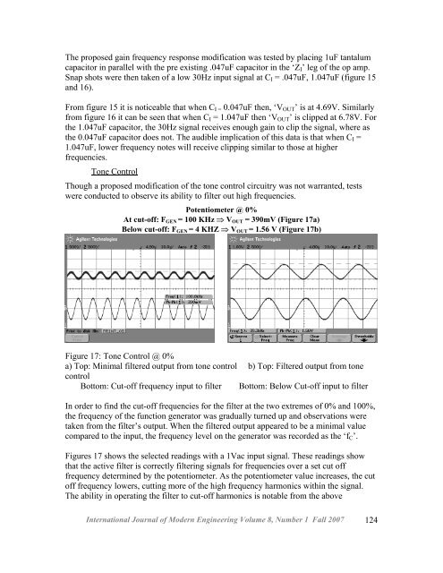
The proposed gain frequency resp<strong>on</strong>se modificati<strong>on</strong> was tested by placing 1uF tantalumcapacitor in parallel with the pre existing .047uF capacitor in the ‘Z I ’ leg of the op amp.Snap shots were then taken of a low 30Hz input signal at C I = .047uF, 1.047uF (figure 15and 16).From figure 15 it is noticeable that when C I = 0.047uF then, ‘V OUT ’ is at 4.69V. Similarlyfrom figure 16 it can be seen that when C I = 1.047uF then ‘V OUT ’ is clipped at 6.78V. Forthe 1.047uF capacitor, the 30Hz signal receives enough gain to clip the signal, where asthe 0.047uF capacitor does not. The audible implicati<strong>on</strong> of this data is that when C I =1.047uF, lower frequency notes will receive clipping similar to those at higherfrequencies.T<strong>on</strong>e C<strong>on</strong>trolThough a proposed modificati<strong>on</strong> of the t<strong>on</strong>e c<strong>on</strong>trol circuitry was not warranted, testswere c<strong>on</strong>ducted to observe its ability to filter out high frequencies.Potentiometer @ 0%At cut-off: F GEN = 100 KHz ⇒ V OUT = 390mV (Figure 17a)Below cut-off: F GEN = 4 KHZ ⇒ V OUT = 1.56 V (Figure 17b)Figure 17: T<strong>on</strong>e C<strong>on</strong>trol @ 0%a) Top: Minimal filtered output from t<strong>on</strong>e c<strong>on</strong>trol b) Top: Filtered output from t<strong>on</strong>ec<strong>on</strong>trolBottom: Cut-off frequency input to filter Bottom: Below Cut-off input to filterIn order to find the cut-off frequencies <str<strong>on</strong>g>for</str<strong>on</strong>g> the filter at the two extremes of 0% and 100%,the frequency of the functi<strong>on</strong> generator was gradually turned up and observati<strong>on</strong>s weretaken from the filter’s output. When the filtered output appeared to be a minimal valuecompared to the input, the frequency level <strong>on</strong> the generator was recorded as the ‘f C ’.Figures 17 shows the selected readings with a 1Vac input signal. These readings showthat the active filter is correctly filtering signals <str<strong>on</strong>g>for</str<strong>on</strong>g> frequencies over a set cut offfrequency determined by the potentiometer. As the potentiometer value increases, the cutoff frequency lowers, cutting more of the high frequency harm<strong>on</strong>ics within the signal.The ability in operating the filter to cut-off harm<strong>on</strong>ics is notable from the aboveInternati<strong>on</strong>al Journal of Modern Engineering Volume 8, Number 1 Fall 2007 124