A New Design for Audio Clipping Pre-amplifiers Based on ... - IJME
A New Design for Audio Clipping Pre-amplifiers Based on ... - IJME
A New Design for Audio Clipping Pre-amplifiers Based on ... - IJME

You also want an ePaper? Increase the reach of your titles
YUMPU automatically turns print PDFs into web optimized ePapers that Google loves.
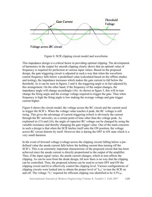
Figure 6: SCR clipping circuit model and wave<str<strong>on</strong>g>for</str<strong>on</strong>g>msThis impedance design is a critical factor in providing optimal clipping. The developmentof harm<strong>on</strong>ics in the output <str<strong>on</strong>g>for</str<strong>on</strong>g> smooth clipping clearly shows that an optimal value offrequency is required <str<strong>on</strong>g>for</str<strong>on</strong>g> perfecti<strong>on</strong> at various input values. <str<strong>on</strong>g>Based</str<strong>on</strong>g> <strong>on</strong> the proposeddesign, the gate triggering circuit is adjusted in such a way that when the wave<str<strong>on</strong>g>for</str<strong>on</strong>g>mcentral frequency falls below a predefined value (calculated based <strong>on</strong> the offline studiesand testing), the impedance increases which makes the gate current to fall below thethreshold. As it can be seen in figures 3 and 4, the triggering angle is in fact adjusted bythis arrangement. On the other hand, if the frequency of the output changes, theimpedance angle will change accordingly (16). As shown in figure 5, this will in turnchange the firing angle and the average voltage required to trigger the gate. Thus whenfrequency is high the firing angle is low making the average voltage and gate triggercurrent higher.Figure 6 shows the circuit model, the voltage across the RC circuit and the current usedto trigger the SCR’s. When the voltage value reaches it peak, the RC voltage is stillrising. This gives the advantage of current triggering (which is obviously the currentthrough the RC network), <strong>on</strong> a certain point of time other than the voltage peak. Asexplained in (15) and (16), the angle of capacitor RC voltage can be changed by using thevariable resistance and thereby changing the gate trigger value. One of the main c<strong>on</strong>cernsin such a design is that when the SCR latches itself <strong>on</strong>to the ON positi<strong>on</strong>, the voltageacross RC circuit distorts by itself. However this is during the OFF to ON state which is avery small durati<strong>on</strong>.In the event of <str<strong>on</strong>g>for</str<strong>on</strong>g>ward voltage (voltage across the clipping circuit) falling below a predefinedvalue the anode current falls below the holding current thus turning off theSCR’s. This is an extremely important characteristic of the proposed circuit that has beenachieved since the anode current is directly proporti<strong>on</strong>al to the output of the amplifier.Thus, if the input signal varies, the anode current changes, which in turn affects theclipping. As can be seen from the diode design, till now there is no way that the clippingcan be c<strong>on</strong>trolled. Thus, the proposed scheme can be used to a) turn OFF and ON theclipping circuit and b) to effectively c<strong>on</strong>trol the clipping level. Various c<strong>on</strong>figurati<strong>on</strong>s ofclipping circuits were looked into to obtain the proper level of ‘I GT ’ to turn the SCR <strong>on</strong>and off. The voltage ‘V 2 ’ required <str<strong>on</strong>g>for</str<strong>on</strong>g> efficient clipping was identified to be 4.5V DC .Internati<strong>on</strong>al Journal of Modern Engineering Volume 8, Number 1 Fall 2007 119