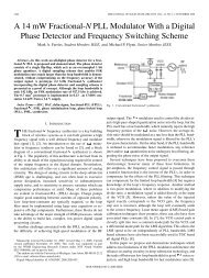
www.ietdl.orgFig. 3Proposed transition from CBCPW <strong>to</strong> <strong>rectangular</strong> <strong>waveguide</strong>a CBCPW <strong>to</strong> <strong>rectangular</strong> <strong>waveguide</strong> transition. It includes a transition from CBCPW <strong>to</strong> CPW, CPW <strong>to</strong> reduced-height <strong>waveguide</strong> mode and reduced-height<strong>waveguide</strong> mode <strong>to</strong> standard <strong>waveguide</strong> modeb Top view, side view and a side view of the back-<strong>to</strong>-back structurec Equivalent circuit model for the transition for Z CBCPW ¼ 50 V, Z CPW ¼ 85 V, X t ¼ 2j 140 V, X ¼ 2j 110 V, n ¼ 1, X b ¼ 2j 8 V, X p ¼ +j 58 V,X step ¼ 2j 1000 V, l backshort ¼ 5mm¼ l g /3, l 2 ¼ 10 mm ¼ 2l g /3, l 3 ¼ 17 mm. Waveguide dimensions are set as the standard dimensions of WR-28Ka-band <strong>waveguide</strong>sd Reflection and transmission coefficients of the circuit model of the back-<strong>to</strong>-back structure for the initial values of the elements <strong>to</strong> achieve a low conversion lossFig. 4 Optimised transition with HFSS is compared <strong>to</strong> the initialdesign based on the circuit model for a back-<strong>to</strong>-back transitionand shows good agreement and improved performancethe <strong>to</strong>p. Basically the <strong>to</strong>p layer and the membrane areprotecting the active components that excite or receive the<strong>waveguide</strong> signal. <strong>In</strong> order <strong>to</strong> test the transition and be able<strong>to</strong> make contact <strong>to</strong> the probe, the <strong>to</strong>p layer of the membraneis also patterned with a CPW line and is connected <strong>to</strong> thebot<strong>to</strong>m layer through via holes as shown in Fig. 7. Withthis transition, the structure can be fed from the <strong>to</strong>p by50 V GSG probes.To fabricate this structure at Ka-band, the lower partsincluding the CBCPW, reduced-height <strong>waveguide</strong> andstandard-height <strong>waveguide</strong> are machined on an ultramachinablealloy 360 brass plate and are gold-plated <strong>to</strong>prevent oxidation. Rogers Duroid 5880 with 1/4 oz (8mm)electrodeposited copper foil is used as the <strong>to</strong>p cover of the<strong>waveguide</strong> as well as the membrane for CBCPW. Thethickness of the substrate is chosen <strong>to</strong> be 0.127 mm (5 mil),thin enough <strong>to</strong> act as the membrane. Both sides of thesubstrate are patterned and connected by metalised via holesas shown in Fig. 7. Additional vias are drilled in thesubstrate in order <strong>to</strong> suppress the substrate mode. Thefabricated parts are represented in Fig. 8.446 IET Microw. Antennas Propag., 2012, Vol. 6, Iss. 4, pp. 443–449& The <strong>In</strong>stitution of Engineering and Technology 2012doi: 10.1049/iet-map.2011.0194
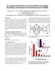
www.ietdl.orgFig. 5The optimised structurea Electric field distribution at 30 GHz for a back-<strong>to</strong>-back transition with S 1 ¼ 1.46 mm, W 1 ¼ 0.37 mm, S 2 ¼ 0.972 mm, W 2 ¼ 0.247 mm, W WG ¼ 7.112 mm,h WG ¼ 3.556 mm, h 1 ¼ 0.379 mm, h 2 ¼ 1.65 mm, t ¼ 0.49 mm, l 1 ¼ 5.024 mm, l 2 ¼ 9.97 mm and l 3 ¼ 16.8 mmb Side view: E-<strong>plane</strong> cross section (<strong>waveguide</strong> centre at maximum E-field)c Reflection and transmission coefficients for the back-<strong>to</strong>-back transition at Ka-bandd Transmission coefficient at the passbandDifferent techniques were tested <strong>to</strong> bond the substrate <strong>to</strong> thebrass unit. <strong>In</strong>itially solder paste and silver epoxy were used.However, since a high temperature is needed for pastesand epoxies, the substrate was warped and damaged, andthe brass unit was oxidised. Also, the results were notsatisfac<strong>to</strong>ry because of misalignments and air gaps aroundthe edges. <strong>In</strong> addition, the solder reflow caused shortcircuits in the substrate during the bonding process.Moreover, many times the thin pins were bent and easilyFig. 6Bandwidth enhancementa Proposed three-pole structure for enhanced bandwidthbS-parameters of the transitionBandwidth of the transition is increased <strong>to</strong> about 15% as a result of having athree-pole structure by adding one resonance, a shorting pin and a stepdiscontinuity with h 3 ¼ 2.26 mm, l 1 ¼ 5 mm, l 2 ¼ 10 mm, l 4 ¼ 3.3 mm,l 5 ¼ 6 mm. Additional resonances can be introduced for further enhancement.broken during bonding at high temperatures. The best resultswere obtained by screwing the two units <strong>to</strong>gether. Since thesubstrate is very thin, a thick metal plate is used on <strong>to</strong>p of it<strong>to</strong> ensure that sufficient pressure is applied <strong>to</strong> the substrateand brass unit <strong>to</strong> prevent possible air gaps. The silver-platedlong rigid steel wires are snapped in<strong>to</strong> holes drilled on thebot<strong>to</strong>m of the reduced-height <strong>waveguide</strong> and soldered. Thepins pass through holes cut on the substrate <strong>to</strong> facilitatealignment of the substrate and the unit.After bonding, the structure is fed by ground-signal-ground(GSG) probes connected <strong>to</strong> the network analyser using Kabandflexible cables. Prior <strong>to</strong> measurement it is essentialthat the probes and cables be calibrated. For this purpose,on-substrate thru-reflect-line (TRL) calibration lines aresimulated and designed. For TRL calibration, threecalibration standards are fabricated on the same substrate.These include two line segments with known phase shiftsfor thru measurements and an open-ended line with aknown electrical length for reflection measurement. Aftercalibration, S-parameters of the transition are measured andpresented in Fig. 9. The measurement results show a goodagreement with the simulation, around 9% of the bandwidthbelow 210 dB for return loss and over 21 dB for insertionloss. The observed deviations from the simulation areattributed <strong>to</strong> misalignment, especially near the pin positionsand possible air gaps between the substrate and the brassunit. The air gap should be of lesser concern since screwsconnecting the substrate <strong>to</strong> the brass unit should applyenough pressure <strong>to</strong> make good metal-<strong>to</strong>-metal contact.Since alignment is done with hand, small misalignment canlead <strong>to</strong> small deviations from the ideal response. Toexamine this hypothesis, a simulation was carried out wherethe <strong>to</strong>p substrate was shifted <strong>to</strong> one side by a very smallamount <strong>to</strong> produce about 300 mm translational displacementat the pin position. This is a typical length that might bemisaligned by manually aligning. Fig. 10 shows theIET Microw. Antennas Propag., 2012, Vol. 6, Iss. 4, pp. 443–449 447doi: 10.1049/iet-map.2011.0194 & The <strong>In</strong>stitution of Engineering and Technology 2012


![[Sample B: Approval/Signature Sheet]](https://img.yumpu.com/34084789/1/190x245/sample-b-approval-signature-sheet.jpg?quality=85)