
You also want an ePaper? Increase the reach of your titles
YUMPU automatically turns print PDFs into web optimized ePapers that Google loves.
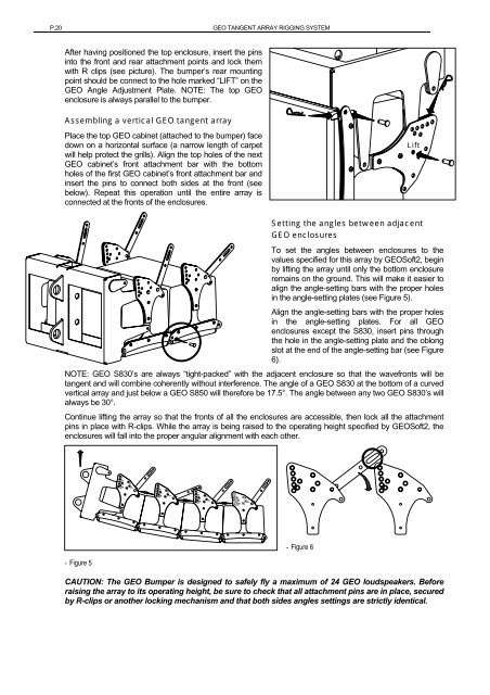
P.20 <strong>GEO</strong> TANGENT ARRAY RIGGING SYSTEMAfter having positioned the top enclosure, insert the pinsinto the front and rear attachment points and lock themwith R clips (see picture). The bumper’s rear mountingpoint should be connect to the hole marked “LIFT” on the<strong>GEO</strong> Angle Adjustment Plate. NOTE: The top <strong>GEO</strong>enclosure is always parallel to the bumper.Assembling a vertical <strong>GEO</strong> tangent arrayPlace the top <strong>GEO</strong> cabinet (attached to the bumper) facedown on a horizontal surface (a narrow length of carpetwill help protect the grills). Align the top holes of the next<strong>GEO</strong> cabinet’s front attachment bar with the bottomholes of the first <strong>GEO</strong> cabinet’s front attachment bar andinsert the pins to connect both sides at the front (seebelow). Repeat this operation until the entire array isconnected at the fronts of the enclosures.LiftSetting the angles between adjacent<strong>GEO</strong> enclosuresTo set the angles between enclosures to thevalues specified for this array by <strong>GEO</strong>Soft2, beginby lifting the array until only the bottom enclosureremains on the ground. This will make it easier toalign the angle-setting bars with the proper holesin the angle-setting plates (see Figure 5).Align the angle-setting bars with the proper holesin the angle-setting plates. For all <strong>GEO</strong>enclosures except the S830, insert pins throughthe hole in the angle-setting plate and the oblongslot at the end of the angle-setting bar (see Figure6).NOTE: <strong>GEO</strong> S830’s are always “tight-packed” with the adjacent enclosure so that the wavefronts will betangent and will combine coherently without interference. The angle of a <strong>GEO</strong> S830 at the bottom of a curvedvertical array and just below a <strong>GEO</strong> S850 will therefore be 17.5°. The angle between any two <strong>GEO</strong> S830’s willalways be 30°.Continue lifting the array so that the fronts of all the enclosures are accessible, then lock all the attachmentpins in place with R-clips. While the array is being raised to the operating height specified by <strong>GEO</strong>Soft2, theenclosures will fall into the proper angular alignment with each other.- Figure 5- Figure 6CAUTION: The <strong>GEO</strong> Bumper is designed to safely fly a maximum of 24 <strong>GEO</strong> loudspeakers. Beforeraising the array to its operating height, be sure to check that all attachment pins are in place, securedby R-clips or another locking mechanism and that both sides angles settings are strictly identical.