
You also want an ePaper? Increase the reach of your titles
YUMPU automatically turns print PDFs into web optimized ePapers that Google loves.
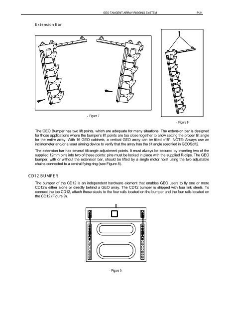
<strong>GEO</strong> TANGENT ARRAY RIGGING SYSTEM P.21Extension Bar- Figure 7- Figure 8The <strong>GEO</strong> Bumper has two lift points, which are adequate for many situations. The extension bar is designedfor those applications where the bumper’s lift points are too close together to allow setting the proper tilt anglefor the entire array. With 16 <strong>GEO</strong> cabinets, a vertical <strong>GEO</strong> array can be tilted ±15°. NOTE: Always use aninclinometer and/or a laser aiming device to verify that the array has the tilt angle specified in <strong>GEO</strong>Soft2.The extension bar has several tilt-angle adjustment points. It must always be secured by inserting two of thesupplied 12mm pins into two of these points: pins must be locked in place with the supplied R-clips. The <strong>GEO</strong>bumper, with or without the extension bar, should be lifted by a single motor hoist using the two adjustablechains connected to a central flying ring (see Figure 8).CD12 BUMPERThe bumper of the CD12 is an independent hardware element that enables <strong>GEO</strong> users to fly one or moreCD12’s either alone or directly behind a <strong>GEO</strong> array. The CD12 bumper is shipped with four link steels. Toconnect the top CD12, attach these steels to the four rails located on the bumper and the four rails located onthe CD12 (Figure 9).- Figure 9