
Create successful ePaper yourself
Turn your PDF publications into a flip-book with our unique Google optimized e-Paper software.
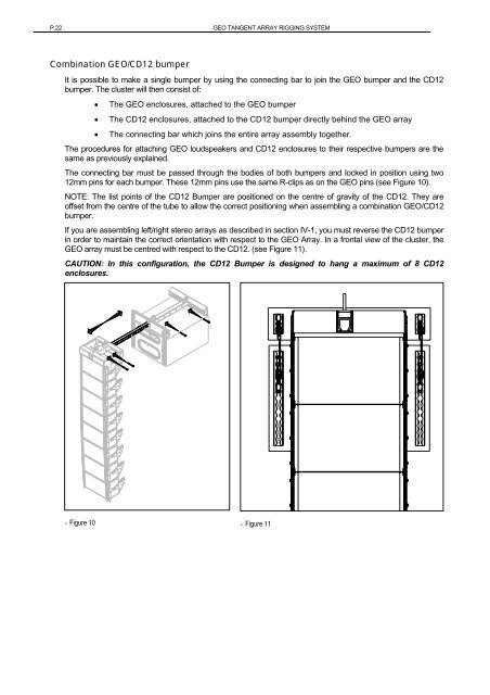
P.22 <strong>GEO</strong> TANGENT ARRAY RIGGING SYSTEMCombination <strong>GEO</strong>/CD12 bumperIt is possible to make a single bumper by using the connecting bar to join the <strong>GEO</strong> bumper and the CD12bumper. The cluster will then consist of:• The <strong>GEO</strong> enclosures, attached to the <strong>GEO</strong> bumper• The CD12 enclosures, attached to the CD12 bumper directly behind the <strong>GEO</strong> array• The connecting bar which joins the entire array assembly together.The procedures for attaching <strong>GEO</strong> loudspeakers and CD12 enclosures to their respective bumpers are thesame as previously explained.The connecting bar must be passed through the bodies of both bumpers and locked in position using two12mm pins for each bumper. These 12mm pins use the same R-clips as on the <strong>GEO</strong> pins (see Figure 10).NOTE: The list points of the CD12 Bumper are positioned on the centre of gravity of the CD12. They areoffset from the centre of the tube to allow the correct positioning when assembling a combination <strong>GEO</strong>/CD12bumper.If you are assembling left/right stereo arrays as described in section IV-1, you must reverse the CD12 bumperin order to maintain the correct orientation with respect to the <strong>GEO</strong> Array. In a frontal view of the cluster, the<strong>GEO</strong> array must be centred with respect to the CD12. (see Figure 11).CAUTION: In this configuration, the CD12 Bumper is designed to hang a maximum of 8 CD12enclosures.- Figure 10 - Figure 11