Un ed States Patent
Un ed States Patent
Un ed States Patent

Create successful ePaper yourself
Turn your PDF publications into a flip-book with our unique Google optimized e-Paper software.
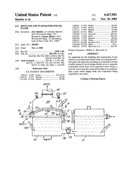
<strong>Un</strong> <strong>ed</strong> <strong>States</strong> <strong>Patent</strong>S~c et al.Ill] 4,417,951~ Nov. 2~ 1983[54] DISTILLER AND EVAPORATOR FOR SEA I~8~861 6/1926 Walker ...............................55/186WATER1fl2~5378/1929Waters...............................55/1861fl7~7737/1930Hackett..............................55/186[76] Inventors: Jovo Stani~ c/o George SpectoL 1~2~42810/193! Miller ...............................203/993615 Woolworth Bldg., 2331)3~96411/1933Gensecke............................202/197Broadway; George Spectoh 3615~201~61 5/1940Stoltz...............................202/197Woolworth Bldg., 233 Broadway, ~90~509 9/1959Helmers..............................203/99both of New York, N.Y. 100073~2~215 2/1962Weber...............................202/1973,279,533 10/1966Kersteteret al ....................202/197[21]Appl. No.: 20a,0633,532,606 10/1970Sibert...............................203/1~69~3219/1972Marovichet al ...................202/197[22] Fil<strong>ed</strong>: Nov. 3, 1980Prima~ Examiner--Wilb~ L. B~com~ J~[51] InL Cl) ................................................C02F 1/04[52] U.S. Cl .......................................202/197; 55/18~ABSTRACT122/492; 202/17~ 203/1; 203/2; 203/10;An appar~us ~r the ~stilhng and evap~ating of sea203/40; 159/DIG. 26water so ~ produce pu~ ff~h w~er on a large produ~[58] Field of Search ................... 203/40, 1, 2, 99, 100,fion bails; the appar~us ~u~ng an evapor~or hav~g203/10, 11; 202/197, 17~ 234; 55/185, 18~159/27 A, DIG. 2~ DIG. I; 122/492a ba~e sy~em of novd defign ther~n so as to separateevapor~<strong>ed</strong> steam from nomevapor~<strong>ed</strong> water drop~ a[56] References Cit<strong>ed</strong>du~ ~r conve~ng the evapom~d ~eam ~ a conden~rU.S. PATENT DOCUMENTSand a pure water sup~y ~n~ the evapor~or bring700~74 5/1902 Roake .............................202/185 Dsupp<strong>ed</strong> by ~a w~e~1~2~I01 4/1917 Pac~ga .................................55/1861,511,854 10/1924 W~ers ..................................55/1864
U.S. <strong>Patent</strong>Nov. 29, 1983 4,417,951
4,417,951DISTILLER AND EVAPORATORFOR S~drMns water from the evapormor when ff~becomesheavily saturat<strong>ed</strong> with brin~ Another drainpipe 16 withWATER ’ a colMction canM 17 ~ a ring plme 15 colMc~ nonevaporM<strong>ed</strong>brine water droplets. ~ :T~s ~vem~n r~es g~em~y m eq~pmem ~r ~e 5 The evaporator ~ provid<strong>ed</strong> wffh a water Mv~ gauge~ation and ~~ ~ ~a w~ ¯ 18, vacuum gauge 1~ a manom~er 19A and a s~om~It h wall known that ~th inc~as~g ~p~ the~ te~ , ~ ....is an ~c~g ~n~m~ of drin~ng w~er, and In the evaporator, the steam space 24 g ~NMd withwkh a g~ ~fi~z~o~ ~e ~ a h~ amoum baffles 2~,21 and 22, for the evapora~d ~eam. The10 purpose of the baffles N to separNevaporat<strong>ed</strong> steamof pure water ~q~d ~ various en~rg<strong>ed</strong> and newph~es of manu~ufing W~u~. Accor~n~% ~om non-evapor~<strong>ed</strong> water drops wh~h are not asthere ~ ~ a more ne<strong>ed</strong> to find other sources of jet-pure as distilMd ~eam. Each baffle 2~ and 21 aspu~ w~ than ~ pr~enfly b~ng o~n<strong>ed</strong> from ~k~, shown in FIG. 2, has ope~ngs 23 of diffuser shape.rivers and the 1~ pa~u~fly ~ ~ew that more and Such diffuser-shap<strong>ed</strong> openings acc~r~e the separ~nmore of k ~ ~ p~l~<strong>ed</strong> due to chem~s of l~ of saturat<strong>ed</strong> ~eam. The last component baffle 22 forms~du~ and w~te of mod~n ~v~g b~ng dump<strong>ed</strong>~ d~oy~g the n~ur~ puny of such waterbo~. It i~ ~e~, n~ur~ ~ a~enfion ~ nowa Nst barrier for non~vaporat<strong>ed</strong> water drops and fordisti~<strong>ed</strong> geam before entering steam space 2& Thebaffle surNce N equM ~ area to the ~Nde transverseb~ng ~ven to obt~n pur~ flesh w~ o~ of s~y ~a area of the evapor~or, and is arcuate for more effectivew~ ~ ~ me~ ~e p~nt day ~q~me~s. In ~me 20 separ~ion of distill<strong>ed</strong> ~eam. The lowermo~ baffle 2~countries flesh water ~ ration<strong>ed</strong> pa~afly ~ dry or has the Nrge~ surNc~ and on ~s peripherN <strong>ed</strong>ge has ahot season~colMcting vault 25 in which non-evapor~<strong>ed</strong> waterAccor~n~ ~ ~ a prin~p~ o~e~ of the w~em drops colMct and are convey<strong>ed</strong> to the drNn canM 17 ~~vem~n ~ prov~e an ~W~ ~s~Mr and evapor~tot ~r converting sea w~ ~ pure ff~h w~. 25 througri hng plat~h~5~iffuseE rVap°ratesh dape~teao mpeNnf~s°m2;reaand2~hePnAnther o~e~ h to pin,de a distiller and evaporator~r ~a w~ w~ch ~ one pa~uhr deign can be ~g coupe and b~ng partly dives~d of water drop~#nge on the second component baffle 21 while changus<strong>ed</strong>aboard a sh~ whe~ ~ t~s time there ~ a gre~ After g~ng through the openings 23 of the secondwa~e of he~ by ~e exhau~ g~ of ~e large en~n~baffle 21 pure steam and non-evaporat<strong>ed</strong> water dropspas~ng out of the s~p ~nnd and ~to the ~mosphe~, 30 are separ~<strong>ed</strong>, the pure ~eam then Maving ~eam spaceand wh~n t~s w~d heat ~ the ~nnd can be h~ness<strong>ed</strong>to produce ~ of the s~s ~q~mem of ~h24 through outlet pipe 14 to the condenseLTwo or more baffles ~ a same evapormor may bewater during an ocean voyag~ ~t any ad~fion~expens~ The ~a w~ us<strong>ed</strong> ~ co~ ~e en~n~ can beemploye~ as may be req~r<strong>ed</strong> for ma~mum effect.us<strong>ed</strong> as ~ ~ ~ready p~e~<strong>ed</strong> ~ to 45 degrees cen~ 35 In FIG. ~ a mottle design of ~ffuser opening 23 ~grad~ so it ~ ready ~r ~o~n.provid<strong>ed</strong> by a diffuser 30 of Venturi shape wffh dectriccontac~ 31 and 32 on 0ppo~te ~des so thin ~rge w~erO~ o~ec~ are to pro~de a distiller and evaporator~r ~a w~ w~ch ~ ~m~e in deign, inexpensiv<strong>ed</strong>rops entering the same will dose an dectric~c~t~ manu~ rugg<strong>ed</strong> in con~ru~ easy to use andthat will thus cause a spark thin will vaporize the w~ereffl~em ~ ~.40 drop. Thus preventing water drop passage therethrough.Contact 31 ~ ~ationary whim contact 32 isThese and ~~s ~1 be ready e~dem upona ~udy of the ~l~w~g ~e~fic~n and the accomp~ slidable closer ~her~o where ~eam pre~ure ~de arean~ng ~a~ wh~n26 is increas<strong>ed</strong>, at wh~h time there are Mrger concentrationof w~er drops so that they must be vaporiz<strong>ed</strong>.FIG. 1 ~ a ~mmm~c ~de vMw of a sy~em of the~em ~venfion.45 T~s ~ accomplish<strong>ed</strong> by a hollow accordian shap<strong>ed</strong>,FIG. 2 ~ an e~g<strong>ed</strong> det~ ~ cross section of ~e expandable case 33 interconnect<strong>ed</strong> to area 2~ andim~r baffle co~u~n ~e ~o~ t~ ~ong which pushes a #votabM lever 34 connect<strong>ed</strong> to slide 35section 2--2 of FIG. 1.which carries contact 32.FIG. 3 ~ a ~p ~ew ~ ~e baffle con~rucfion ~de While various changes may be made in the d~ilthe evapor~o~ as ~ew<strong>ed</strong> ~ direction 3--3 of FIG. 1. 50 construction, ff ~ unde~tood that such changes will beFIG. 4 ~ a cross secfion~ew on fi~ 4--4 of FIG. within the s#rit and scope of the present ~vention as ~1. defin<strong>ed</strong> by the append<strong>ed</strong>Mms.FIG. 5 is an e~g<strong>ed</strong> cross secfion~ ~ew on fine The following ~ dMme~5--5 of FI~ ~ ~o~ a peripher~ dr~nage can~. 1. A Sea water distiller comprising a sea w~er supplyFIG. 6 ~ a mo~ficafion of the ~venfion show~g a 55 tank connect<strong>ed</strong> by a conduito the bottom of an evaporatorwith heating mean~ ~duding a ring plmecross section ~rough a mottl<strong>ed</strong> ~se~. The proem ~vent~n is ~own ~ FIG. 1 to ~ude mount<strong>ed</strong> around the ~de periphery of sMd evaporatoran evapor~or 10 and a sea water sup~y water tank 11 at a pr<strong>ed</strong>~erm~<strong>ed</strong> levd, s~d ring pl~e ~u~ng aw~ch are ~onne~<strong>ed</strong> by a sup~y ~pe 12 ha~ng a pefipher~ dr~nage can~ ~ com~nation with a pluralsup~yv~ve 1~ w~ch ~ a~om~c~y ~g~<strong>ed</strong> by 60 Ry of spac<strong>ed</strong> venally curvate baffles above s~d pl~¯ e water Mvd ~t~n the evaporato~ The ~p of the the lowermo~ of s~d baffles having a peripher~ <strong>ed</strong>geevapor~or ~ connect<strong>ed</strong> w~h a condenser ~ot show~ portion<strong>ed</strong> above and l~er~ly adjacent s~d can~by a ~pe 14 ~r ~u~ ~o~ steam ~to ~econdenser whe~ a vacuum ~ o~n<strong>ed</strong> by vacuum ~e~whereby moi~ure ~ direct<strong>ed</strong> and dron<strong>ed</strong> from s~dbaffle to s~d can~, ~ fu~her combination with a dr~ntor~~ ~ow~. Condens<strong>ed</strong> water from a condens<strong>ed</strong>65 age pipe having an inl~ ~ commu~c~n wffh s~dsuction pump ~ show~ ~k~ wa~r and discharges k~ drin~ng w~er mn~ ~ ~ow~. A dr~n ~pe ~show~ ~ the b~mm of the evapor~or periodicallycanM for drayage purposes, sMd baffles having upwardorient<strong>ed</strong> diffusers and an upper solid baffle superimpos<strong>ed</strong>over sMd baffles with the diffuser~ sMd upper2
3baffle having an outer <strong>ed</strong>ge spac<strong>ed</strong> from evaporator~ner sur~ce whereby deflect<strong>ed</strong> ~eam vapor ~ direc~dpefipher~ly to the s~d <strong>ed</strong>ge and to a ~eam space aboves~d upper baffle ~duding a ~eam outlet above s~d~eam space wheron s~d diffusers ~duding means forvafia~y restrict~g water drops from pas~ng therethroughcompiling a Vemufi sect~n in s~d diffusers4,417,9514wi~ O~c~ m~ns ~ ~e Ve~ufi ~n ~r v~ofiz-~g water drops upon con~ of sa~ de~fic~ meanswith water drop~2. A ~sfil~r ~ ~ clam 1 wh~n s~d de~fic~means include ~e~fic con~ vafia~y spac<strong>ed</strong> respon-~ve to steam pressure.10152o253O355055
<strong>Un</strong> <strong>ed</strong> <strong>States</strong> <strong>Patent</strong>EII~ J~Ill]<strong>Patent</strong> Number:~ Date of PatenUWATER DEGASIFICATION AND3,479,949 11/1969Reynoldset al ......................99/295DISTILLATION APPARATUSL53L60610/1970Sibert...............................202/180L83E016 9/1974Powers...............................~ Invento~202/181John ~ EIH~ J~ 1084 P~m~ Ave, L935,0771/1976Dennison............................202/180LarchmonL N.Y. 10538~081~31 3/1978Weiss................................202/181~1] Ap~. N~: 48~767~13L984 1/1979Kirschmann..........................202/83~17~84212/1979Vitous...............................99/295~ ~l<strong>ed</strong>: Ap~ 2~ 1983~18~150 2/1980Rich............................203/DIG. 16~24L369 1/1981Bean................................202/181Rd~<strong>ed</strong> ~ A~ ~~25~616 2/1981Glazer...............................202/181~261fl964/1981Lemoine.............................202/181C~u~a~ ~ ~ No. 26~88~ Ju~ 3, 1981, ~269~63 5/1981McFee................................202/202Pa~ N~ ~3~.~41~95111/1983Stanisicet al .......................202/197~42~37412/1983Ellis................................202/176~1] InL ~? ...........................B01D 3/0~ ~2F 1~[5~ ~ ~ .....................................~ 202/18~FOREIGN PATENT DOCUMENTS202/181; 202/185.5; 2~/188; 202/19~202/197; 202/202; 202/23~ ~2~ ~203/1~ 203~ 203/2~ 203/DIG. 16;109551 1/1940 Amtmha .............................202/196Prima~ Examiner~Wiibur B~comb~ 22 Attorney, Agen~ or Firm--Eugene E Geoffre~ JL~ ~fld of Seth ..................... 202/188, 185.5, 17~ABSTRACT202/19~ 2~ 19~ 181, 18~ 83, 19~ 19~ 19~195, 202; ~. 17, 1~ I1, DIG. 2~ 2~ W~er deg~ific~n and ~stillation apparatus ha~ng aDIG. 16; 99/295 cont~ner ~r wa~er to be dega~fi<strong>ed</strong> and ~still<strong>ed</strong>, a~ R~ ~t<strong>ed</strong>~lativ~y small boiler a~ng s~d container and ha~~g a first condor e~en~ng ~to the cont~ner so thin a~S. PATENT DOCUMENTSs~e~<strong>ed</strong> wmer ~v~ ~ ~e confiner will fill s~d boiler284~II 8/1883Her~ck .......................~3~ 17 to a s~ec~d h~ght, a condenser w~n the con~er771,832 I~19~ R~ ..............................~I~ and immer~d ~ the water contain<strong>ed</strong> there,, a second851,~5 ~1907 ~ck ................................20~/196 cond~t e~en~ng ~om the space above the water ~9~9,6259/1910Ho~et ~ .....................2~/I~ s~d b~r to the ~t of the condense, an outlet on theI~I~508 2/1911 ~Cu~ ..............................202/196 condenser ex~n~ng ~rough a cont~ner w~] for ~~13~8 10/1938 Kess~ .................................202/1892~75~82 7/1949~em~s ..............................202/194char~ng dega~fi<strong>ed</strong> and ~s~d water and heating3~2~214 2/1962B<strong>ed</strong>uhn e~ ~ ....................203~0 X means m s~d boiler for heating the water therei~3~2~215 2/1962W~er ...............................203~ X3~4~305 ~1966 W~|~m~n .....................202/19~ X
U.S. Patem s~ 1~ 1~6 ~t3 ~S 4~12~90
U.S. <strong>Patent</strong> se~ 16, 1986 She~ 4 of 8 4,612,090
U.S. <strong>Patent</strong> se~ 1~ 1986 She~5 of 8 4,612,090
~S. Patem sev 16, 1986 S~ 6 ~8 4~12~900 o 0
-U.S. Palm s~ 16, 1986 S~ 7 a8 4~12~900
U.S. <strong>Patent</strong> se~ 16, 1986 She~ 8 of 8 4,612,090
~61~090A s~l ~h~ o~e~ of the invention re,des ~ theWATER DEGA~CA~ON AND D~LLA~ON prov~ion of a novd and ~ wm~ d~c~APPARATUSand d~t~n apparatus char~ri~d by ~s ~m~ff~ ~ ~~ and mMn~nance and r~mi~y ~wTMs ap~m~n ~ a continuation-in~a~ cf applic~ 5 cos~tion Se~ N~ 269,880 ~<strong>ed</strong> June 3, 1981 entitl<strong>ed</strong> "Wmer A s~l ~h~ o~e~ of the ~vention ~Nd~ ~ theDegasification and D~tillm~n Apparatus" now U.S. provM~ ~ a ~vd ~d ~pro~d b~ ~r ~e ~s~Pro. No. ~42~37~fion of water wNch mi~m~ ~e accum~ation ofTh~ ~vention r~a~s to d~ng apparmus and mo~ ~am ~ the b~er caus<strong>ed</strong> by sNt~ d~e~ and otherspe~ficflly to novd and improv<strong>ed</strong> water ~fl~tion10 water ~ma~ms wMch can ~nm~ the waterapparatus.bNng ~s~&Known ~sti~ng apparmus generally ~v~ve ~eutil~m~n of a dos<strong>ed</strong> boiler and means ~r continuoufly ~c~dan~ ~ ~e ~v~fion ~ud~ a ~n~r ~~e~ng wmer to the boiler. As the wmer ~ the boil~ m m~ ~d ~ ~c~ ~e wm~ ~ ~ ~s~d. A ~heat<strong>ed</strong> to produce wmer vapor or ~eam, v~ati~ cherub15 b~Mr ha~ng he~ng demems mourn<strong>ed</strong> ~on ~ p~Gc~ componen~ of water ha~ng boiling p~nts ~wer e~ secur<strong>ed</strong> to one ~de of the rank and a fl~d condMtcou#~ ~e bMMr ~ ~e rank ~ ~ ~e l~d Mvdthan the wmer will boil off and combine with the steam.The steam tog~her with the v~a~e vaporiz<strong>ed</strong> chemic~compone~s will then be condens<strong>ed</strong> ~ a s~tab~m ~e b~ ~H be conffdMd by ~e fiq~d Mvd ~ ~econdenser so that the ~sdm~ ~s~ wffi cont~n the 20 a__condense~ ank" A ~eam~o~ly~and ~ap°r ~d°Ufl~ ~ ~nthe b~er~ ~mkeou#<strong>ed</strong> tov~a~e chemic~ In ca~s wher~n ~e wmer has a outlet of the conden~r ex~nds ~rough the w~ of th<strong>ed</strong>isagreeable odor produc<strong>ed</strong> by s~phur compounds and tanZ The conden~r may be ~ ~ such a mann~~m ~e hq~d ~ ~e mk ~H ~r pm ~ ~ ~ ~ethe ~k~ known apparatus ~nds to concentra~ the odorcondenseL ~ ~ a~mm and wffh the heatersanp drior u.sm āke th;a~WateNr~ eve4, n33~30m 7°~fUlg "ran~d j~yApN~ant’l s3, 1982 25 ~ ~e bMMr ~g ~ ~e ~uM ~ ~e ~r ~Hen~tl<strong>ed</strong>: "D~tillm~u Apparmuf’ dNcloses distiNng heat Mmo~ ~anmneoufly and ~em ~H be ~ outappar~us embod~ng upper and ~wer chambers with ¯rough the condenseL As the p~e wff~ thethe condenNng coil ~spo~d ~ the upper chamber b~er exce<strong>ed</strong>s the capm~ of the outlet to rec~vewMch N normally fill<strong>ed</strong> wi~h w~er and graduNly ~d steam or water v~oL p~u~ will ~e water in theinto the ~wer chamber wNch N heat<strong>ed</strong> by a s~tab~means ~ order to prodnce geam. The steam g then ~d~ ~ ~& wm~ ~H ~Mn ~w ~o ~e b~upwardly through a condenser ~ the upper chamberand ~ then discharg<strong>ed</strong> ~om the condenser as a ~q~& ~ of the d~ apparatus. ~nee hot wmer ~By opiating the apparmus ~r a sho~ period of time 35 b~ c~smfly ~d ~ ~e mk and ~ ~m ~prior to the co~ection of the ~<strong>ed</strong> wate~ the condens~w~ ~cre~e ~e ~mperature of the wa~r ~ thecon~anfly ~mov<strong>ed</strong> ~om the c~m~ by ~e w~er~t~n ~e tanL ~e w~ wi~ ~e tank w~ ~e~eupper chamber ~nd bNl off vMa~e chemicN comp~ ~ mm~e and b~ off ~M ~e~c~ ~nent~tMn<strong>ed</strong> ~ ~e wm~ prior m ~s~lm~n ~e~o~ C~dTh~ ~vention constitutes an improvement over prior~ water ~ ~r~y ~d to ~e mk at ~e ~Mt to theknown ~stilling apparatus ~u~ng the apparmus d~dos<strong>ed</strong>~ apN~ant’s prior U~d Stat~ pment ~ Ihm ~ time ~e b~ ~ ~M~ Means may M~ be pro~d~b~ler so that the boiler wiB ree~ve cold wmer ~hembod~s a novd and improv<strong>ed</strong> smNI bNler ~ud~g ~ a~o~afion w~h the rank ~r ~e~ng condens<strong>ed</strong> ~instantaneous ~eating mean~ a conden~r ~nd a re~b ~Md ~d ~g~d ~ ~m ~e~ ~s ~rvNr wNch pro~d~ ~n a~omatic supNy ef wm~ to the 45 ma~ng co~ tea or merdy pro~de hot wmer ~rbN~r and may Nnction to con the condenser. With other pu~th~ arrangement, lhe water ~ the ~rvN~ ~ w~ be The ~ove and other ~ec~ and advanmg~ of theshowm ~rcMm~ m and from the boiler to repeme~y ~v~ti~ w~ become mo~ appa~m ~m the ~w-~rrupt boiling and hem thus impal<strong>ed</strong> lo the wmer ~ ~g ~ri~ and ~mpan~ d~ ~rm~g¯ e re~rvNr tog~her w~h ~e hem m ~t pa~ of ~ pa~ of t~s ~#c~.wMch may be impal<strong>ed</strong> by the condenser wffi heat thewater in the ~rvNr to a ~mperatu~ that w~ effectivdyboil off chemicN constituents of the water and FI~ 1 ~ a ~agmemary p~ ~w ~e m~mm~ ~E D~N~the time req~d for operation of the ~stil~r ~ order ~ ~ d~g ~m ~ ~e ~h ~ ~to produce a ~stillate free of the m~als and undesirab~ 55 tio~odors ~ mmeriN~ r<strong>ed</strong>uc<strong>ed</strong>.FIG. 2 ~ a ~o~ ~ctionM ~ew of FIG. 1 ~ ~Another o~ect of the ~vention reNdes ~ the provi- the ~ne 2--2 ~e~o~~on of novd and improv<strong>ed</strong> wmer dgtiHation apparmus FIG. 3 ~ a cro~ ~ctionM ~ew of FIG. 1 token MongwNch not o~y avNds co~rM means for fe<strong>ed</strong>~g wm~ the ~ne 3--3 ~e~and ~t~ ~ ~cd~ meansfrom a re~rvoir ~o a bNler but also embodi~ an arrangeme~and orga~zation of ~ements wher~n all FIG. 4 ~ a cro~ sectionM ~ew of the b~er and a60 cam<strong>ed</strong> by the comMne~potions of both the reservoir and boiler are readily ~agmemary po~on ~ the tank token ~ong the l~eacc~s~ for ~ea~ng and m~ntenanc~~ thereof of FIG. ~A still N~her o~e~ of the ~vention reNdes ~ the FIG. ~ ~ a ~de d~M ~ew of a mottl<strong>ed</strong> emprovisionof hot ~stil~d and sub~antially odobffee65 bo~mem of ~e ~vem~n ~r produ~ng d~Md wm~water ~r the brewing of coffee and ~a ~ well as for use ~r ~e and other ~od~~n the preparation of other ~ods such as soups and the FIG. 6 ~ a cro~ ~ctionM ~ew of FIG. 3 token Mong~k~the ~e a--6 m~eo~2
3~61~090FIG. 7 ~ a fide devafionfl ~ew ~ parti~ section of 41 and the boiler can be readily disassem~<strong>ed</strong> for deaning.The heating dements 13 and 14 in the ~ant em-the water tank and b~Mr of FIG. 5;FIG. 8 ~ a cross ~ction~ew of FIG. 5 taken ~ong bo~ment of the ~vention are carri<strong>ed</strong> by the w~141 andthe line 8--8 thereo~are connect<strong>ed</strong> in series by a lead 44 connecting oneFIG. 9 ~ a cro~ sectional ~ew ~ pe~pective of a 5 ~rmin~ of one heater to one term~ of the othermo~fi<strong>ed</strong> embo~ment of a d~fiNer ~ accordance wkh heate~ The power ~ne 45 has one lead 46 connect<strong>ed</strong> tothe invenfio~the other ~rm~ of the he~er 14 while the second leadFIG. 10 ~ a fragmentary crcss ~ction~ew of still 47 ~ connect<strong>ed</strong> through a thermo~ 48 to the otheranother embo~ment of the ~ventio~termin~ of the heater 13. The thermo~ is moun~d onFIG. 11 ~ an dev~ion~ ~ew of the water Mvd 10 a bracket 49 ~ dose pro~mky to the heater 13 and incontrol of FIG. 1~the even the heater 13 reaches a ~mperature above theFIG. 12 ~ an devation~ ~ew ~ partifl section taken norm~ operat~g ~mperatur~ the thermo~at will operateto open the drc~t and d~energ~e both heaters 13~ong the Nne 12--12 of FIG. 1~FIG. 13 is a cross sectionfl ~ew of FIG. 12 taken and 1~ R ~ evident however that heaters 13 and 14flong the l~e 13--13 thereo~15 cord be arrang<strong>ed</strong> for paralld operation or ~ the ~te~FIG. 14 ~ a cross section~ew of FIG. 13 taken nativ~ a ~ngle he~er may be employ<strong>ed</strong> provid<strong>ed</strong> howeverk drivers the quantky of heat necessary for oper~~ong the fine 14--14 thereo~ andFIG. 15 ~ a top ~ew ~ parti~ section of the boiler tion of the apparatu~shown ~ FIG. 10.If de,r<strong>ed</strong>, the tank or cont~ner 10 may be prov~<strong>ed</strong>Re~rring now to the drawings and more sp<strong>ed</strong>fic~ly 20 with a convention~ cover having openings therdn or ~to FIGS. 1 through ~ the ~g apparatus ~ acco~ the ~ternative may util~e forc<strong>ed</strong> ~r Orculation meansdance with the ~vention compds~ a cylindric~ tank or for the remov~ of unde~rable vapo~ Hbera~d from thecont~ner 10 ha~ng a p~r of handMs 11 secur<strong>ed</strong> to the Nquid w~hin the tank 10 during the course of the d~tillationprocess. One embodiment of air circulating meansfide thereo£ A boiler 12 ha~ng in~antaneous heatingdements 13 and 14 ther~n ~ affix<strong>ed</strong> to the fide of the25 ~ illustrat<strong>ed</strong> in FIG. & The ~r drculating means ifidudesan ~ve~<strong>ed</strong> dish<strong>ed</strong> cover gener~ly denot<strong>ed</strong> bytank 10 by the fl~d connectors 15 and 1~ The fl~dconnector 15 ~dud~ an ~bow 17 ha~ng a sho~der 18 the numer~ 50 which ~dudes a flat upper wall 51, anand a thread<strong>ed</strong> shank e~en~ng through cooperm~g upwardly extending pefipher~ wall 52 and a downwardlycurv<strong>ed</strong> peripher~ w~l 53. The lower peripher~ope~ngs ~ the wall 19 of the b~Mr 12 and the wM1 ofthe tank 10. A nut 20 engages the shank of the fitting 15 30 <strong>ed</strong>ge of the wMl 53 carries three or more angularlyand tog~her with a resilMnt w~her 21 pro~d~ a wv dispos<strong>ed</strong> rolM~ 54 each having space discs 55 rota~~r-tight seM for both the tank 10 and the b~ler 12. A ably carri<strong>ed</strong> by a sha~ ~ The discs 55 engage thewmer i~ tube 22 ~ fixe~y cou#<strong>ed</strong> to the fitting 13 by rolMd <strong>ed</strong>ge 10’ of the tank 10 and accordin~y providemeans of a nut 23 so that water wren the tank 10 will an annular vent b~ween the cover 15 and the <strong>ed</strong>ges ofbe automaticaNy ~d ~to the b~Mr 12 until the water35 the tank 10.levd wff~n the b~ler co~esponds to the wmer levd ~ The wall 51 of the ~r drculat~g means shown ~the tanL ~ w~ Mso be observ<strong>ed</strong> thin the wmer Mvd ~ FIG. 3 includes a motor gener~ly denot<strong>ed</strong> by the numer~57 which has a sha~ 58 extending through thethe tank ~ pre~raMy mMntMn<strong>ed</strong> m a Mvd to effe~ |olMor ~ Mast sub~antiM immerfion of the heating dements perforat<strong>ed</strong> wall 51 and carries a fan 59. Power ~ f<strong>ed</strong> to13 and ~4 ~ the wmer wff~n the boiler.40 the motor 57 by a ca~e 60 connect<strong>ed</strong> in a convention~The ~eam outlet fltt~g 16 ~ of conventionM con- manner to the moto~ If des~<strong>ed</strong>, sw~ch means may be~ruction and ~dud~ an outlet #pc 24, a thread<strong>ed</strong> provid<strong>ed</strong> for operation of the fan. The fan motor ~shank 2~ ex~nd~g through the walls of the tank and cover<strong>ed</strong> by a dome~hap<strong>ed</strong> houfing 61 securdy fi~<strong>ed</strong> tothe boiler and secur<strong>ed</strong> thereto by a nut 25. A sealing the cover 53 and secur<strong>ed</strong> thereto by any s~ta~e means.w~her 26 ~ d~po~d b~ween 1he tank and the boiler Io45 In the in~ant embodiment of lhe ~vention, the domeshap<strong>ed</strong>houfing 61 ~ adapt<strong>ed</strong> to frictionally engage thepro~de a w~evtight connection. The condenser 27 ~the ~ant embo~ment of the ~vention ~ ~ the form of peripher~ wall 52 of the cover 50. In operation, ~r ~a c~Md tube of m~M such as ~M~s ~<strong>ed</strong>, copper or drawn in through an opening 62 and the perforat<strong>ed</strong> wallthe Nke and has the ~Mt end potion 28 seMably connect<strong>ed</strong>to the fitting 16 wit~n the tank 10. The oufl~ 29 50 in the container and d~charg<strong>ed</strong> through the annular51 whereupon k ~ direct<strong>ed</strong>ownwardly over the w~erof the condenser 27 has a fitt~g 30 ex~nd~g through opening between the container 10 and cover 50.the wall cf the tank 10 and pro~d~ the fl~d oufl~ 31. In the operation of the di~ill~ion apparatus d~The tank fu~her ~dud~ ~n overflow p~e 22 w~ch ~ scrib<strong>ed</strong> abov~ the tank 10 and boiler 12 are fir~ filMdconnect<strong>ed</strong> to a fitt~g 33 seal<strong>ed</strong> to the wMl of the tank 10 with water to a Mvd at Mast substantially covering theand a drMn cock 34 for drM~ng l~d from the tanL A 55 heating dements 13 and 14 as wi~ be observ<strong>ed</strong> morew~er ~Mt vMve 34 ~ card<strong>ed</strong> m the upper potion of the deafly in FIG. 2. R will be observ<strong>ed</strong> th~ when fill~gtank or contMner 10 and has an inlet 3~ an outlet 37 the tank 10, water wi~ automatically flow through conduit22 ~to the boiler so that the Mvd of the water inwithin the tank and a hand-wheal 38 for reg~ating thewmer sup#y ~ order to mMntMn substantially constant lhe lank will be lhe same as the wa~r Mvd in the boile~Mvd of lhe w~er wff~n the tank.60 Energy ~ then suppN<strong>ed</strong> to the heating demen~ 13 andThe boiler ~ shown more deafly ~ FIG. 4 and confi~sof two hous~g demen~ 39 and 40. A drc~ar wMl boiler 12. S~am ~om lhe boiler win emerge through14 which win function to boil the water wkhin theor partition 41 ~ ~spos<strong>ed</strong> b~ween the houfing demen~ the outlet 24 and then flow through the condenser 1739 and 40 and ~dudes a p<strong>ed</strong>pherM seM 42 w~ch ~ and the condens<strong>ed</strong> ~eam will then be d~charg<strong>ed</strong> as ardeasably damp<strong>ed</strong> b~ween the outer alms of the hou~ 65 Hq~d ~om the outlet 31. When initi~ly operating this~g dements 39 and 40 by clips 43 about the periphery apparatu~ k ~ gener~ly defirabM to discard the d~tillateuntil the water within the tank 10 has attun<strong>ed</strong> aof the boiler 12. T~s arrangement com~etely ~Ms thechamber form<strong>ed</strong> by the hous~g posen 39 and the wall normally operat<strong>ed</strong> ~mperature which ~ ra~dly ~-4
5~61Z090tin<strong>ed</strong> in the following manne~ HeMers 13 and 14 are fion a ~m~ircd~ brackm 84 of L6hap<strong>ed</strong> section ~rdefign<strong>ed</strong> to hem the water wit~n the boiler at a rate ¯ dably recoving a basket 85 ~u~ramd ~ brokendines~ster than the condenser 27 can accommodMe the ~ FIG. 5 wMch may normally h~d a fi~er and groundsteam produc<strong>ed</strong>. Accordin~ pressure ~ devdop<strong>ed</strong> coffee. A base 86 engages and suppo~s the Z-shap<strong>ed</strong>within the boiler 12 and will force ~q~d ~om the boiler5 brack~ 72 and ~Oud~ a convenfionM de.fie heatingthrough the tube 22 back ~to the ~nk 1~ As soon as the dement 8% The heating dement 87 ~ prodd<strong>ed</strong> wffhpressure ~ reliev<strong>ed</strong> w~n the boile~ water w~ ag~n suitabl ener#zing conducmn and swim~ng means not~ow through the tube 22 back ~to the b~r w~h the shown so that ff may be turn<strong>ed</strong> on and off as defi~&resdt that there w~ be a perio~c reve~ of water The space b~ween ~e b~mm of ~e basket 85 and ~eflow through the tube 22. T~s action resu~s ~ a sub-10 top of the heating demem 87 ~ of ~ffident magnitude~anti~ ~crease ~ temperature of the wa~r w~n Ihe to ~cdve a s~m~e ~cepm~e 88 ~r ~c~ng b~wCd~nk 10 and contributes to the he~ impal<strong>ed</strong> to the coffee. It ~ ob~o~ ~om ~e ~g~ng d~cus~on thMwMer ~ the ~nk 10 by the action of the condenser 2~ the basket 85 may be a~ang<strong>ed</strong> to aceommodMe teaThe ~mper~ure of the w~er tank 10 however ~ ~- ~aves ~r the brewing of tea or ~ the ~rnative theways brow the boiling ~mperature and shodd pre~ra-15 distill<strong>ed</strong> water ~om the fittMg 83 can be f<strong>ed</strong> ~ctly~y be ~ the range of 180’ F. to 19& ~ ~ order to be ~to ~e ~ce~ac~ 88 ~r making soup or any otherce~n that undesirab~ componen~ ~ the water are purple ~r w~ch purifi<strong>ed</strong> ~s~l<strong>ed</strong> w~ may be ~-boil<strong>ed</strong> off prior to a~u~ d~tiH~n.q~&In one form of the ~vention utilizing a tank 10 hating The cont~ner 70 ~dud~ a ~sh<strong>ed</strong> cover gener~lya v~ume ~f 1 to 2 gallons of w~e~ a b~lCr 12 h~d~g20 denot<strong>ed</strong> by the num~ 89 wMch may be affix<strong>ed</strong> ~ theappro~m~dy 16 ounces of wate~ heating dements contMner 70 by any s~tab~ mean~ The cover 89 ~-deign<strong>ed</strong> to d~fipMe from 1,500 to ~000 wMt~ ~ wffi ~udes an ope~ng 90 for ~e~ng wMer ~to the cont~ner70 and a cooperat~g rid 91. Forc<strong>ed</strong> Mr O~-take appro~m~dy 15 minu~s of operM~n for thewater ~ the ~nk to reach a ~mperature of approxim~dy18~ ~ lo 19& F. and the b~r wffi normally25 ri<strong>ed</strong> on the top ~de of the cover 91 and ~dud~ an~g means general~ denot<strong>ed</strong> by the nume~l 92 ~ ca~hem tap water above the boiling p~nt wit~n about 45 de~ric m~or and ~n subs~ntially ~mil~ ~ ~M ~u~second~ W~h t~s a~angement and after the warm-up tm~d and describ<strong>ed</strong> m connection wi~ FIG. & The airperiod, subsmnfi~ly all v~atile chem~s ~ the wa~r circ~ating means ~dud~ an air inl~ opening 93 on theare boil<strong>ed</strong> off prior lo ~stil~tion with the resdthM the mp ~de ~eof and appropriMe ope~ngs not shownd~tiHMe ~ subs~nfi~ly odorless and bee of all unde~ 30 a~ ~rm<strong>ed</strong> ~ the top of the cover 89 ~ permk theab~ component~ In actu~ te~ ~ has been found that ~oduction of ~r ~to the space defin<strong>ed</strong> by the cont~ner70 and Hd 8~ The ~r ~ exhau~<strong>ed</strong> from one orw~h distillation apparatus as describ<strong>ed</strong> abov~ distill<strong>ed</strong>w~er w~ be produc<strong>ed</strong> ~ the rate of on~h~f to thre~ mo~ oufle~ 94 ~ the cover and an dectdc cab~ 95 ~quarters of a gallon per hou~utiliz<strong>ed</strong> ~r en~ng ~e ~n and may ~dude appro-A mottl<strong>ed</strong> form of the ~vention ~ ~ustra~d ~ 35 prime swish mean~FIGS. 5 through 8. Th~ form of the ~vention m m- The operation of ~e apparat~ illu~t<strong>ed</strong> ~ FIGS. ~tend<strong>ed</strong> for the brewing of coffee and for the production ¯rough 8 ~ mb~anti~ly ~e~ to thM describ<strong>ed</strong> ~of hot d~til~d wMer for other purposesuch as the connection wi~ the p~ce~ng embo~me~ of the m-brewing of te~ ma~ng of soups and the ~ke.ventiom Howeve~ ~nce the defice ~ not a~ang<strong>ed</strong>,~ w~ become apparent ~om the following descriptionof FIGS. ~ through 8 of the drawings thM the ~ ~e com~ner ~ initiMly ~d wi~ w~ ~o ~ ~e~ ~ough k may b~ ~r the continuous ~ffiation of w~operation cf the brewer ~ substantially ~entic~ to lhe ~vd ~ ju~ brow the portion of ~e ~1~ 81 of theoperation of the form of the invention shown ~ FIGS. condenser 80. g ~e container 70 ~ of mffidet s~ |he1 through & More speOfic~l~ the brewer comprises a d~lation proce~ can continue until the vessd 88 hastank or cont~ner 70 having an outwardy form<strong>ed</strong> pe-4ripherM ~p 71. The conta~er ~ suppos<strong>ed</strong> by a p~r of q~ ad~tion~ wMer can be add<strong>ed</strong> through thebeen ~d. If ~rger amounts of ~s~d wM~r are re-Z-shap<strong>ed</strong> brack~s 72 cou~<strong>ed</strong> by a transverse dement ope~ng 90 as may be ~q~d ~ order ~ m~nt~n the72 w~ch m~nt~ns the two brack~s 72 ~ spac<strong>ed</strong> rdafions~p.The confiner 70 ~ suppos<strong>ed</strong> by the upper cause ~e heating dements ~ the boiler 74 ~ be M ~ast~vd of ~e wM~ ~ ~e container M a h~g~ ~M w~horizont~ bracket potions 73 w~ch engage ~e peripher~p71 on the ~des of the cont~ner 70. A b~r Re~rring now to ~e ~rms of the ~venfion shown ~50 ~a~ially covere&74 substantially ~entic~ to the boiler 12 shown on FIG. FIG. 9 and FIG~ 10 ~rough 1~ ~ has been ~und th~4 ~ affix<strong>ed</strong> to one end of the confiner 7~ ~nce the improv<strong>ed</strong> results can be obtain<strong>ed</strong> by ~<strong>ed</strong>ing the wat~boiler functions ~ the same manner as the b~ler 12 and sup~y controll<strong>ed</strong> by lhe wM~ inl~ v~ve 35 as sho~n~ substantially ~entic~er~ a fu~her description ~ 55 ~r ~s~nce ~ FIG. 1, ~rough an dongat<strong>ed</strong> tube 37tot deem<strong>ed</strong> necessary.w~ch ~rm~ates adj~ng lhe bo:l~ i~ 22’. TheThe boiler 74 ~ cou~<strong>ed</strong> to the confiner 70 by a wM~ inl~ tube ~7’ ~ p~rab~ a~ang<strong>ed</strong> ~ swivd ~fitt~g 75 having a w~er inlet 76 secur<strong>ed</strong> to one ~de ~dicat<strong>ed</strong> ~ FIG. 9 so ~ ~ can ~e rais<strong>ed</strong> ~ ~cilita~lhereof and a w~er out~t 77 d~pos<strong>ed</strong> w~n the boiler a~u~mem of ~e w~ ~<strong>ed</strong> ~ just main~ ~e defi<strong>ed</strong>74. A second fitting 78 extends through the walls of the60 wMer ~vd ~ the cont~ner 10 as de~rib<strong>ed</strong> ~ connectionw~h FIGS. 1 and ~ It w~ be observ<strong>ed</strong> ~ thecont~ner 70 and boiler 74 and card~ a ~ream outlet 79on one end thereo~ WitCh the confiner, the ~t end water inlet 22’ to ~e boiler ~ a ~rmght tube ~a~ng81 of the condenser 80 ~ affix<strong>ed</strong> to the fitting 78 and the ¯ ~etly ~ ~e ~w~ po~icn of ~e b~r and ~ atilt!on~ ~c~ng c~d ~let wM~ ~ctly from ~e ~beoutlet end 82 of the condenser ~ secur<strong>ed</strong> to a fitting 83extend~g through an ope~ng ~ the bottom of the65 3T, ~e tube 22’ ~ ea~ ~ ~e~n as w~ be ~d ~cont~ner 70.more detail m connection with FIGS. 10 ~rough 15.The underfide of the cont~ner 70 as shown ~ FIGS. It has been ~und ~ ~e ~s~fion of wM~ ~M ~e5 and 8 ~dudes ~ the ~stant embodiment of the ~ve~ presence of s~, de~rgen~ and o~ ~mil~ chemicals6
~61L090~nd m cause the generat~n of foam in the boiler wh~h ing 10~ As v~w<strong>ed</strong> in FIGS. 10 and 13, the baffle whichadve~dy affects the dfimate distilhm and Mso neces~tatesmore ~equent dea~ng of the apparatus to attMn to the left so that the L-shap<strong>ed</strong> steam outlet 118 which~ of ~rc~ar configuration ~ inclin<strong>ed</strong>ownwardly andoptimum resets. A ~ructure for achieving lhes ends is ~ coupl<strong>ed</strong> to the fitting 16 ~es to the left of the baffle asillustrat<strong>ed</strong> in FIGS. 10 through 15 wheron the contMnerfor recoving the water sup#y ~ generally de-right ~de of the baffl~ The baffle ~ hid in place by a5 view<strong>ed</strong> in these figures while the heaters 111 are on thenot<strong>ed</strong> by the numerM lff while the b~Mr ~ generMly b~t 119 carri<strong>ed</strong> by the wall 103’ of the boiler sectiondenot<strong>ed</strong> by the numerM 12~ The boiMr 12’ ~ secur<strong>ed</strong> to 103 and extending through an opening in the baffle 117the contMner lff in the same manner as describ<strong>ed</strong> in to recove a cooperating nut 120 to hold the baffle inconnection wffh FIGS. I and 2 in thin lower and upper10 position. The baffle Mso includes a centrMly d~pos<strong>ed</strong>seM<strong>ed</strong> fittings 15 and 16 secure the boiler to the contMnerand at the same time provide a lower water inMt portion 122 extending inwardly ~om the fitting 15 pre-ope~ng 121 to recove the end of a water inlet tubeand an upper ~eam outleL The end of the fitting 16 viou~y describ<strong>ed</strong>. The ~eam outl~ tube as view<strong>ed</strong> ind~pcs<strong>ed</strong> wffh the contMner 10 ~ coupl<strong>ed</strong> to the inlet cf FIG. 12 preferably l~s b~ween 30° and 50* to the le~ ofcondenser 29 and the outlet of condenser 29 ~ con-1nect<strong>ed</strong> to an outlet fitting 30 which in~udes d~till<strong>ed</strong> holes 123 dispos<strong>ed</strong> wall to the right cf the center line ofverticM and the baffle 117 includes a plurMity of smallwater d~charge means having a pipe 31, an rusticoupling100 and an elbow 101 to facilffme collection of the generat<strong>ed</strong> principMly on the heater ~de of the baffle 117the boiMr 103. W~h this arrangemenL foam will b<strong>ed</strong>istilMd water in a suitabM receptaO~ The inl~ pipe 2T with the resulthat the baffle will tend to confine theextends through the fitting 15 and into the b~Mr in a 20 foam with only the ~eam or water vapor pas~ngmanner to be describ<strong>ed</strong> in connection with the succe<strong>ed</strong>ingfigures.thermor ~nce the ~eam outlet 118 ~ angularly d~-through the openings 123 to the ~eam outlet 118. FurRe~rring now to FIG~ 12 through 15, the boiler ~ pos<strong>ed</strong> r~ative to the openings 123, foam which mayform<strong>ed</strong> of two ~uncat<strong>ed</strong> hem~phericM or bowllike pos~bly pa~ through the openings 123 will not reachportions 102 and 103 having integrally form<strong>ed</strong> ~os<strong>ed</strong>25 the ~eam outlet 118 easily and accordingly only thebottom portions 10T and 103’ respectively. The boiler ~eam will pa~ through the ~eam outleL This actionsection 102 ~ provid<strong>ed</strong> wffh a peripherM flange 104 resul~ in the ~tainment of much purer water than in thewhile the boiler section 103 ~ provid<strong>ed</strong> wffh a ~miMr case where foam can reach the steam outlet and ultim~dybe recombin<strong>ed</strong> with the d~tilMte.peripherM flange 105. The boiMr sections 102 and 103are separat<strong>ed</strong> by a separate plate or partition 106 having30 Referring agMn to FIGS. 10 and 11, the contMner 10’a diameter ju~ slightly greater than the diameter of the includes an overflow control assembly generMly denol<strong>ed</strong>by the numerM 124. This a~embly inOudes aperipherM flanges 104 and 105. An annular U-shap<strong>ed</strong>gask~ 107 ~ fi~<strong>ed</strong> about the <strong>ed</strong>ge of the partition 106 fitting 12~ extending through the wall of the containerand a plurMffy of clips 108 engage the peripherM flanges 10’ and carrying an L-shap<strong>ed</strong> tube 126 rotatably dis-104 and 105 to secure the boiler portions one to the35 pos<strong>ed</strong> within the fitting. A hou~ng portion 127 rota~other and at the same time seM the boiler 103. For convenienceof assembly, the pa~ifion 106 wffh the gasket having soft and hard pos~ions as illustrat<strong>ed</strong> moreably recoves the tube 126 and suppo~s a fix<strong>ed</strong> scMe 128107 ~ secur<strong>ed</strong> in position rdative to the boiler section ~eafly in FIG. 11. A shaft 129 extends ~om the hou~ng102 by an dongat<strong>ed</strong> screw 109 extending through the 127 and ~ mechanicMly coupl<strong>ed</strong> to the tubular memberend wM1 102’ of the boiMr section 102 and through a 40 126 so that rotation of the shaft 129 will rotate the tubecen~M opening in the pa~ition and ~ secur<strong>ed</strong> in place 126 to move the angularly d~pos<strong>ed</strong> end potion 126’ ofby a s~tabM nut 110 and sealing washer 11ff.the tube 1264o Other a horizontM position or a verticMA pMr of heaters 111 idenficM to the heaters 13 and 14 position as illustrat<strong>ed</strong>. A knob 130 having a point<strong>ed</strong>of FIGE I and 2 are carri<strong>ed</strong> [y the pa~ition 106 and are portion 131 ~ carri<strong>ed</strong> by the shaft 129 and ~O~tesdispos<strong>ed</strong> slightly brow the central axis cf lhe boileL As 45 rotation of the shafto one or the other of the positions.shown in FIG. 1~ each hemer includes ffs individuM Wffh this arrangement, should lhe water be relativdythermostat 112 with each heater and thermo~at being hard, the pointer 130 ~ mov<strong>ed</strong> to the horizontal positionconnect<strong>ed</strong> in seriem The series connect<strong>ed</strong> heaters wffh to ~mit the quantity of water deliver<strong>ed</strong> to the boilertheir assodat<strong>ed</strong> thermostats are then connect<strong>ed</strong> in parMldas shown in FIG. 14 so that ~ne voltage ~ appli<strong>ed</strong> to 50 deliver<strong>ed</strong> to the boiler ~ increas<strong>ed</strong>. The verticM posi-while at the verticM positio~ the quantity of watereach heater and each heater ~ individually protect<strong>ed</strong> tion ~ us<strong>ed</strong> when rdatively soft water ~ encounter<strong>ed</strong>agMn~ overheating. The heating dements of ~ach of ~nce the verticM position will provide increas<strong>ed</strong> waterthe heaters 111 ~ dispos<strong>ed</strong> wffhin the boiler section 103 to the boiler and greater output without any adverseand ~ en~os<strong>ed</strong> by a w~er impervious hou~ng 111’ affect on the distilMte. The horizontM portion resul~ inwh~h not only protects the heating dement but Mso 55 a r<strong>ed</strong>uction of the quantity ~f distillate produc<strong>ed</strong>. It ~ toseMs the heater agMn~ the pa~ition 10& The heaters be underwood that the lower water Mvd will Mwaysare energiz<strong>ed</strong> by a power cabM 112 having three conducto~113, 114 and 115. The conductor 114 ~ a In order to avoi damage to the gasket 107 surround-produce the superior d~tiHat~ground conductor and ~ connect<strong>ed</strong> to the grounding ing the pa~ition 106 in the event pressure shouldescrew116 while the conductors 113 and 115 are con-6nect<strong>ed</strong> to the heating dements as illu~rat<strong>ed</strong> in FIG. l& sur~ a plug 132 form<strong>ed</strong> of plastic materiM ~ loosdyvdop wffhin the boiler 103 exce<strong>ed</strong>ing the de,r<strong>ed</strong> pres-As previou~y point<strong>ed</strong> ouL water for drinking and inse~<strong>ed</strong>a cooperming opening at the top of the boiMrother Furposes often contains relatively large quantitiesas will be observ<strong>ed</strong> more ~eady in FIGS. 10 and 13.of salt~ detergents and other chem~Ms wh~h produce The pre~ure requir<strong>ed</strong> to di~odge the plug 132 ~ exsubstantlMquantities of foam during the distilling pro-6ce~ and ff ~ of course desirabM to preventhe foam of rupturing the boiler 103 or even dislodging the resil-~emdy small so th~ there ~ no poss~ility whatsoever~om entering the condenser 29. For this purpose, a ~nt sealing member 107. In the event one or both of thebaffle 117 ~ angularly d~pos<strong>ed</strong> within the boiler hou~ heating dements 111 shodd become damag<strong>ed</strong> or
9the case may be so that the water w~ com~dy or~61~090burn<strong>ed</strong> ouL the section 102 ~g~h~ wRh the ~tion and a readily accesfible cover ~ate ~movably se~<strong>ed</strong> to106 can ready be ~m~ ~m ~e bA~r ~r ~ac~ s~d open fide ~r ready access to the bA~nmere ~ ~p~n ~ ~e same tim~ it ~ q~e ob~o~ ~ Z Water degafification and ~stiHation apparatusby ~ason of the umque a~n~ and con~ruction accor~ng to d~m 1 wh~n s~d cont~ner ~dud~ a~ ~e d~il~r ~ ~c~d~ ~ ~e ~, ~ ~ 5 cover and ~r ~ating means card<strong>ed</strong> by sfid covehpotions are ready acc~e ~r dean~&In the ~ of the d~tiller ~ ~eo~ w~hthe ~vention ~dud~g the ~rms of the ~ventionshown ~ FIGS. 1 and 2 as w~ as FIGS. 10 and 13, thes~d ~r ~rc~g means ~g ~r ~to s~d conminerand s~d cover ~dud~g means ~r dightings~d ~r from s~d conm~er whe~by vapo~ produc<strong>ed</strong>w~n s~d container are d~charg<strong>ed</strong> ~to the atmosphere.baler is portion<strong>ed</strong> rdative to the cont~ner 10 or lff as 10clemens ~nction to heat the water very m~y ~d asa ~s~t c~e a ~m~ ~ ~e bA~r w~ch ~the water ~t ~e b~ ~d b~k ~ ~e cont~ne~ 15In FIGS. 1 ~d 2 ~nce the hot water ~11 rise ~t~n the~n~r 1~ ~ w~ ~ ~ ~ ~d b~k ~m ~ebAMr but ~ the meantime b~ng has been com#~dym~up~d. ~ FIG~ 10 and 13 w~e the water doesnot e~rdy e~ose the hem~s when d~charg<strong>ed</strong> from 20the b~eL upon ~e~ng of cad water from the ~Mt#~ ~’ ~y m ~e ~ ~’ m ~e b~ ~e c~dwm~ w~ ~rm~e b~g ~ M~t momentarywhe~upon ~e ~ ~d d~ process ~ ~Mn 25~pe~e& H h~ b~n ~und ~ both ~s of the ~nventionthin exce<strong>ed</strong>~#y pure water ~ ~d wMch ~n~ o~M~bM wffh ~y ~h~ known de~c~ ~ compv~le fize and r~e of ~H~. In the ~ of the~vention shown ~ FIGS. 10 and 13, when the waterMvd ~ a~u~<strong>ed</strong> to the Mw Mv~ the pure~ water ~~n~M w~M at the ~gh Mv~ the w~er will meetp~db<strong>ed</strong> ~s ~r ~s~Md wmeL The ~gh Mvd~ prodd<strong>ed</strong> pa~ady ~r use wffh wmer ha~ng lowtotM ~v<strong>ed</strong> s~s and other impudt~s fince the 35~ w~ d~ver as much as three qua~e~ of ag~on of d~ti~<strong>ed</strong> water per hour w~M the apparatuswffh wm~ m ~e ~w Mvd w~ dd~ on~hMf a gM~nper houLW~M o~y ce~n e~m~ of the invention ~have been illustrat<strong>ed</strong> ~d describ<strong>ed</strong>, ff ~ apparent thatM~mtiom, changes and m~c~s may be madewffhom ~ng ~ the ~ue scope and s#~thereo~W~t ~ dMm~ ~: ~1. Wmer ~~ ~d ~11~ apparatuscomprising a contMner ~r h~ng w~er to be dega~fi<strong>ed</strong> and ~ a condenser ~ sMd comMn~ ha~ng~ ~ ~d oufleL ab~ ~vdy ~ v~um~ aMw~ wm~ ~ on sMd b~ ~d commu~c~g ~wffh sMd container at a pare s~y below theMvd of ~e w~ ~ sMd conm~ ~r ~e~ng w~ff<strong>ed</strong>y to ~d ~m sMd b~eL sMd bAMr bong point<strong>ed</strong>~ m ~d ~n~r m ~y mMmMn ap~d~d wamr Mvd ~t~n sMd b~eL an upper 55oufl~ on sMd b~er ~ove sMd ~e~M~ wmerMvd and ~mm~ wAh the ~Mt of sMd condenseLand means ~r being water ~ sMd bAMr andperio~cM~ ~e~ng ff ~effom ~Oud~g a he~ngdemem ~ sMd b~ ~d g~m~g h~t ~ a ~mp~v ~ture ~t to produce steam at a g~ rate thansMd ~eam can ~ ~ha~ from sMd upper omMt~e~ a pressure m sMd b~er ~em to ~rcewmer ~ sMd b~er ba~ ~to sMd contMner ~mugh~d Mw~ w~ ~ ~ ~e ~e~e ~ ~d b~ ~ ~r~ and b~ng ime~up~d wh~eupon w~ w~agMn flow ~m sMd b~ m sMd ~~d Mv~sMd bAMr bring ~<strong>ed</strong> of a fin#e opem~d<strong>ed</strong> hou~ng10& Wa|er deg~ification and ~stiHation apparatusaccording to d~m 2 wh~n s~d cov~ h~ a convexconfiguration, s~d ~r ~g means ~ m the ~rmof an de~ric ~n ha~ng a ~n motor c~fi<strong>ed</strong> by s~dcover and ~n ~ades a~x<strong>ed</strong> to the motor shaft, s~dcover ~du~ng opemngs ~r the admission of fir andmeans about the <strong>ed</strong>ge thereof ~r enga~ng s~d conminerand h~ng ~e <strong>ed</strong>ge of s~d cover ~ spac<strong>ed</strong>rdation~ m sfid container m pro~de ~r ~e ~charge of ~r ~rc~<strong>ed</strong> by s~d ~n.¢ W~er dega~fic~n and ~il~tion appar~maecor~ng to ~m 1 ~dud~g means ~r supportings~d conm~ above a ~pporting sur~c~ and s~dcondenser oufl~ emend~g ~rough the boRom wMl ofm~ cont~ner whereby a vessd may be d~pos<strong>ed</strong> b~neath s~d cont~ner and ~ hne w~h s~d condenseroufl~ m ~c~ve ~e ~s~d w~eL5. W~ degas~cation and d~lation ~pp~accord~g to d~m 4 ~dud~g means on the undersideof s~d container and mrroun~ng s~d condens~ oufl~~r supposing a b~k~ hav~g an ope~ng ~ ~e b~mmthereof ~r ~c~ng and h~ng a ~r eontaimngground coffe~ ~a or the ~ke whe~by s~d d~tiH<strong>ed</strong>w~ w~ first flow ~ said ba~ and ~ence ~ ~aidvessel.~ W~ deg~ification and ~stillation appallsaccording m d~m 1 whe~ said boiler ~ ~rm<strong>ed</strong> of ahollow, ~tantially hemi~he~c~ housing ha~ng aperipheral flange e~en~ng ~om ~e open end potionand pofition<strong>ed</strong> ~ a verfic~ ~an~ ~id cov~ ~e co~~rm~g ~ ~e fize and configuration of said flange anda g~k~ ~<strong>ed</strong> b~ween s~d bA~r and ~e andmeam ~mova~y ~curing s~d ~e and gasket ~ s~dflang~~ Water degafification and ~sti~n app~uscompdfing a coma~ ~r hA~ng w~ ~ te degasifi<strong>ed</strong>and d~till<strong>ed</strong>, a bA~r of ~latively sm~l vAum~ a~wer water inlet on s~d boiler and communicatingwi~ said ¢o~ner ~r ~e~ng w~ m said boiler, saidbA~r b~ng pofition<strong>ed</strong> ~tive to s~d conm~ tonormally m~m~n a pr<strong>ed</strong>eterm~<strong>ed</strong> water ~vd w~ns~d boile~ a condense~ an upper o~t on s~d bA~rabove said pr<strong>ed</strong>etermin<strong>ed</strong> wa~er ~vel and commun~at-~g w~h ~e inl~ of s~d condense~ and heating means~ said boil~ and gen~ating heat ~ a ~mperatu~ sufficfe~~ produce steam ~ a great~ m~ ~an said steamcan be d~charg<strong>ed</strong> from s~d upper oufl~ ~e~g ap~ure m s~d bA~r suffident m ~e w~ ~ s~dbAkr back into s~d container ~rough m~ ~wer waterinl~ un~ ~e p~u~ m s~d boil~ ~ ~ev<strong>ed</strong> whe~uponw~er w~ ag~n flow ~to s~d boiler to s~d p~de~rmin<strong>ed</strong>~vel, s~d bA~r b~ng ~rm<strong>ed</strong> of a fin~eopen-sid<strong>ed</strong> houfing and a ~adi~ accesfib~ cover ~e~movably sefl<strong>ed</strong> to s~d open fide ~r ready access ~¯ e boiler, sfid bA~r bring ~rm<strong>ed</strong> of a hollow, sub~antifllyhem~ph<strong>ed</strong>c~ houfing ha~ng a pefipherfl flangee~en~ng from ~e open end potion and position<strong>ed</strong> ~a v~tic~ ~n~ said cover plate con~rm~g m ~e fize
114,612,090and conflgurm~n of sMd flange and a gask~ ~spos<strong>ed</strong> ~upt<strong>ed</strong> whereupon w~er will agMn flow ~to s~d boilerb~ween sMd b~Mr and #me and means removably to s~d pr<strong>ed</strong>~erm~<strong>ed</strong> lev~, sMd boiler b~ng form<strong>ed</strong> ofsecuring sMd ~me and gask~ to sMd fiang~ sMd he~- a ~n~e open-~d<strong>ed</strong> housing and a readily acce~ible~g means bring an de~ric hemer carri<strong>ed</strong> by sMd ~me cover ~me ~mova~y seM<strong>ed</strong> to sMd open ~de ~r readywith the dectricM connections therefor ~spos<strong>ed</strong> on the 5 acce~ to the boile~ s~d b~Mr ~ud~g a battle ~douter~de of sMd #me and a second h~low, sub~antiallyhemisphericM housing ~du~ng a peripherM outlet d~pos<strong>ed</strong> on one ~de thereof and s~d heating~g sMd boiler into two portions with s~d upper steamflange endoMng sMd decU~M connections and sMd means and ~wer water inlet on the other ~de thereofhou~ngs with sMd cover #me bring removably ~cur<strong>ed</strong> and s~d baffle ~ud~ m Mast one upper ope~ng anguoneto the other~10 lady ~splac<strong>ed</strong> from sMd upper ~eam outl~.8. W~er dega~fication and ~m~n apparatus 10. Water dega~fication and ~stiHation apparatuscompri~ng a contMner for h~ng w~er to be degasifi<strong>ed</strong>and di~ille~ a conden~r ~ sMd container ha~ng h~Mw, subsmntiMly hemisphericM hou~ng ha~ng aaccord~g to ~Mm 1 wher~n sMd b~Mr ~ form<strong>ed</strong> of aan inl~ and outleL a b~Mr of rdativdy small v~um~ a peripherM flange ex~n~ng from the open end, sMdlower wmer ~Mt on sMd boiler and commu~cming15 boiler bring affix<strong>ed</strong> lo the eu~r sMe of said containerwith sMd contMner at a p~nt sub~antiMly bdow the with ~ Mast sMd ~wer w~er inl~ e~en~ng throughMvd of the w~er ther~n for ~e~ng wmer fre~y m and sMd houfing and contMneL a ~<strong>ed</strong> wmer inlet carri<strong>ed</strong> byfrom said boiler, said boiler being position<strong>ed</strong> rd~Ne to sMd contMner for ~e~ng water to sMd contMner ~ thesMd contMner to normally mMnmin a pr<strong>ed</strong>etermin<strong>ed</strong> ~dnity ~f the b~ler wmer ~let, and a wmer cver£owwater levi wit~n sMd boile~ an upper outlet on sMd 20 outlet carri<strong>ed</strong> by sMd contMner to mMnmin a con~antboiler above sMd pr<strong>ed</strong>eterm~<strong>ed</strong> water Mvd and commu~catingwith the ~Mt of sMd condenseL and means 11. Water degasification and ~stilMtion apparatuswater Mvd ~ sMd contMneLfor heating wmer ~ sMd boiler and period~Mly ~ecfing comprising a contMner for h~ng wmer to ~e degasifi<strong>ed</strong>and ~still<strong>ed</strong>, a boiler of relativdy small vMum~ ait therefrom ~dud~g a heating ~ement ~ sMd bMl~and generating hem m a ~mpermure suffidem to pro-2duce ~eam at a gremer rate than sMd ~eam can be with said contMner for ~e~ng wmer to sMd b~ML sMdMwer wmer ~Mt on sMd boiler and commu~cm~gd~charg<strong>ed</strong> from sMd upper outl~ creating a pressure in boiler bring posffion<strong>ed</strong> r~ative to sMd container tosMd b~Mr suffident lo force w~er ~ sMd b~Mr back normally mMntMn a p~<strong>ed</strong>e~rm~<strong>ed</strong> w~er levi wff~n~to sMd contMner through sMd Mwer ~Mt until the sMd boile~ a condenseL an upper outl~ on sMd b~lerpre~ure ~ said boiler ~ rdMv<strong>ed</strong> and boil~g interrupt<strong>ed</strong> 20 above sMd pr<strong>ed</strong>etermin<strong>ed</strong> wmer Mvd and commu~cmwhereuponwmer w~ agMn flow ~to sMd boiler to sMd ~g wffh the inlet of sMd condenseL sMd heating meanspr<strong>ed</strong>~erm~<strong>ed</strong> Mvel, said boiler being form<strong>ed</strong> of a sin#e ~ sMd boiler and generating heat m a ~mperature suffidentto produce steam at a greater rate than said steamopen-sid<strong>ed</strong> hou~ng and a readily acce~ible cover #meremovably seM<strong>ed</strong> to sMd open ~de for ready acce~ to can be d~charg<strong>ed</strong> from sMd upper outl~ creating athe boileL said boiler being form<strong>ed</strong> of hollow, sub~anfiallyhemisphericM hou~ng ha~ng a peripherM flange boiler back ~to said confiner through said lower wmer35 pressure ~ sMd boiler suffident to force water ~ sMdex~nd~g from the open end potion and portion<strong>ed</strong> ~ inl~ until the pre~ure ~ sMd boiler ~ reliev<strong>ed</strong> wher~a ve~M #an~ and sMd cover #me conform~g to the upon w~er w~ ag~n flow ~to s~d boiler to sMd pr~~ze and configurm~n of sfid flange and a gaskm ~ de~rmin<strong>ed</strong> levi, sMd b~Mr bring form<strong>ed</strong> of a ~n#epos<strong>ed</strong> b~ween sMd boiler and #me and means remov-4ably ~curing sMd #me and g~km to sMd flang~ sMd removably seM<strong>ed</strong> to sMd open ~de for ready access toopen-sid<strong>ed</strong> hou~ng and a readily accessible cover #mehollow, substantially hemisphericM hou~ng ~dud~g the b~M~ said boiler being form<strong>ed</strong> of a hollow, ~u~s~nfiMlyhemisphericM hou~ng ha~ng a pefipherM flangean ~clin<strong>ed</strong> baffle with sMd ~eam outlet l~ng on one~de of the baffle and sMd heating means on the other e~en~ng from the open en~ s~d boiler bring affix<strong>ed</strong> to~de of the baffl~ sMd water inlet ~e~ng water to the45 the outer ~de of s~d contMner wffh at M~t sMd lowerheater ~de of sMd baffle and sMd baffle fu~her ~dud- water inlet ex~nd~g through sMd housing and containeLa ~<strong>ed</strong> water inlet carri<strong>ed</strong> by sMd container for~g m lea~ one ope~ng a~M~ng the top <strong>ed</strong>ge andang~ar spac<strong>ed</strong> from the ~eam oufleL~e~ng water to sMd contMner ~ the ~dnity of the¯ Water dega~fication and ~stilMt~n apparatus b~Mr w~er inlet, and a wmer overflow outlet ca~i<strong>ed</strong>compris~g a contMner for hM~ng wmer to be degasi-5fl<strong>ed</strong> and ~stilM~ a condenser ~ s~d contMner ha~ng sMd contMneL sMd wa~r overflow oufl~ compd~ng aby sMd contMner to mMntMn a constant water levi inan inl~ and outlet, a boiler of relatively smM1 vol~m~ a horizontally d~pos<strong>ed</strong> wmer d~charge tube rotmablylower wmer ~Mt on sMd b~Mr and commu~cm~g carri<strong>ed</strong> by a fitt~g e~en~ng through the wall of sMdwffh sMd contMner m a p~nt substantially bdow the containeL the ~ner end of sMd tube bring anguMriyMvd of the w~er there~ for ~e~ng w~er ~<strong>ed</strong>y to and55 ~spos<strong>ed</strong> rdmNe to the rema~der of the tub~ means onfrom sMd b~ML sMd boiler bring position<strong>ed</strong> rdative to the outride of sMd contMner and cou#<strong>ed</strong> to sMd tubesMd contMner to normally mMntMn a pr<strong>ed</strong>etermin<strong>ed</strong> for rotation thereof whereby the Mvd of the water ~w~er Mvd wff~n sMd boileL an upper oufl~ on sMd sMd contMner can be chang<strong>ed</strong> by ang~ady po~fio~ngboiler above sMd pr<strong>ed</strong>etermin<strong>ed</strong> water Mv~ and commu~c~gwith the inl~ of sMd condenseL and means60 12. Water dega~fication and ~m~n apparatusthe ~ner end of sMd tube.for heating wmer ~ said boiler and perio~cMly ~e~g compri~ng a contMner for h~ng water to be degafif<strong>ed</strong>and ~stiH<strong>ed</strong>, a b~Mr of relativdy smM1 v~um~ a~ therefrom ~du~ng a heating ~ement ~ sMd b~Mrand generating he~ ~ a ~mFer~ure suffident lo producesteam at a gremer rate than sMd steam can be wffh sMd contMner for ~<strong>ed</strong>~g wmer to sMd boile~ sMd~wer water inlet on sMd boiler and commu~cating¯ scharg<strong>ed</strong> from sMd upper oufl~ creating a pr~sure ~ 65 boiler bring poskion<strong>ed</strong> rdafive to sMd contMner tosMd b~Mr suffident to force wmer ~ sMd boiler back normally mMntMn a pr<strong>ed</strong>~ermin<strong>ed</strong> w~er Mvd withininto said container through said ~wer wmer inl~ until sMd boileL a condenseL an upper outlet on sfid boilerthe pressure ~ sMd b~Mr ~ reliev<strong>ed</strong> and boiling ~ter- above sMd pr<strong>ed</strong>~erm~<strong>ed</strong> wmer lev~ and commu~cm-12
~61L090~g wffh the ~Mt of sMd condenses and heating means pfis~ at Ma~ one w~erproof de~ric heater carri<strong>ed</strong> by~ sMd boiler and generatMg hem ~ a ~mperMure suffl- sMd #~e wi~ ~e de~ric mrm~Ms ~spo~d on theOem m produce s~am ~ a gre~er r~e lhan sMd ~eam outer fide of sMd #m~can be d~charg<strong>ed</strong> ~om sMd upper oufl~ creating a 1~ Water degafification and distillation apparatuspre~ure ~ sMd boiler suffl~ento force wmer ~ sMd 5 according to dMm 13 wheron sMd boiler houfing indud~a baffle ~fid~g sMd housing M~ two ~para~boiler back ~to said container through said ~wer w~er~Mt until the pressure ~ sMd boiler ~ rehev<strong>ed</strong> whe~uponwmer w~ agMn flow ~to sMd b~Mr to to sMd fide of sMd baffl~ sMd heating means ~spos<strong>ed</strong> on thechamb~s wi~ sMd upper oml~ bong ~spos<strong>ed</strong> on onepr<strong>ed</strong>~erm~<strong>ed</strong> Mv~, sMd b~Mr b~ng form<strong>ed</strong> ofa sin#e other fide of sMd baffle and sMd ~wer w~er inlet ~<strong>ed</strong>open-s~<strong>ed</strong>houfing and a really accesfiMe cover #me10 ~g w~er to the heater fide ofsMd baffle and sMd baffleremovaMy seM<strong>ed</strong> to sMd open fide for ready acce~ to ~du~ng at lea~ one ope~ng near the upper <strong>ed</strong>gethe boileL sMd b~ler comprifing a sub~antiMly round the~of and angu~fly posff~n<strong>ed</strong> ~tive ~ s~d upperbowl6hap<strong>ed</strong> hou~ng ha~ng an omwar~y ex~nd~g ~eam oufleLflang<strong>ed</strong> rim and a flatten<strong>ed</strong> bottom dispos<strong>ed</strong> ~ a vertical 15. Water degafification and ~still~n apparatus#ane and smMler ~ ~ammer than sMd tim, sMd ~wer 15 according to dMm 14 where~ sMd condenser ~ ~water inlet ex~nds through sMd bosom, sMd upper pos<strong>ed</strong> wit~n sMd conmineL sMd b~Mr houfing m s~outlet extends through sMd bosom and carries a tube cur<strong>ed</strong> to the ou~r wall of sMd contMner wffh ~e upperwit~n sMd b~Mr hou~ng curv<strong>ed</strong> upwar~y and m an outl~ and ~wer ~l~ e~en~ng through the wMl ofsMdan#e rdafive to a ve~icM #ane normM to sMd bottom container, means ~r ~e~ng wmer to said container andand a #me conform~g to sMd flange secur<strong>ed</strong> ~ seM<strong>ed</strong>20 a container overflow to mMntMn a wamr Mvd ~ sMdrelationsh~ to sMd flang<strong>ed</strong> rim.contMner th~ will cause sMd boiler houfing to be nov13. Water degasiflcation and distillation apparatus mally ~l<strong>ed</strong> ~ sMd pr<strong>ed</strong>etermin<strong>ed</strong> Mvd.accord~g to OMm 12 wheron sMd heating means com-2514355565
<strong>Un</strong>it<strong>ed</strong> <strong>States</strong> <strong>Patent</strong>EIHs, Jr.I ll[lllllgll lllflll llllllllllllllHlllIHUS~0A[11] <strong>Patent</strong> Numbe~ 5,203,970~q Date of Paten~ Apr. 20, 1993METHOD FOR WATER DEGASIFICATIONAND DISTILLATION~ Invento~ John C. Elfi~ Jr., 1084 PMmer Av~,Larchmont, N.Y. 10538~1] Ap~. No.: 48~228~ Fil<strong>ed</strong>: Feb. 28, 1990FOREIGN PATENT DOCUMENTS8~8 12/1988 World Int. Prop. ~ .~ma~ Exam~er--V~nia Man~aranAttorn~ Ageng or Firm~We~eL Can~ Muter &Hayer~1] InL Ci.5 ........................B01D 3/0~ B01D 19/02; A m~hod ~r w~er d~on and distillation ~ anC02F 1/04 ~ratus ~v~g a conm~er ~r a reservo~ of w~er ~~ U~. Ci ...........................203/1~ 202/175; ~ ~g~d and distill<strong>ed</strong>, a rdafivdy sm~ b~r adj~ng~e con~ner ~d ha~ng a ~<strong>ed</strong> water cond~t202/17@ 202/180; 202/202; 202/203; 202/265;203/4; 203/22; 203/DIG. 18; 203/DIG. 22 co~e~ the con~ner and b~ler so that a s~ec~d~ Fi~ of Search ............ 202/175, 17G 203, 185.5, water ~vd ~ the conm~er w~ ~1 the ~fler to the202/265, 180, 202, 181, 188, 19~ 203/IK G 1, ~e ~v~ a coil~ tu~ condenser whh~ ~e con~er2, 2K DIG. 18, DIG. 22; 55/36 ~mer~d ~ ~e w~er ~ere~ the condenser coil hav-~g a ve~c~y ~spos<strong>ed</strong> ~n~u~n~ a~s, a secondReCreates Cit<strong>ed</strong>condor in the b~r conne~ the space above theU.S. PATENT DOCUMENTSwater levd ther~n to the ~et of the condenser so thatsteam flows ~om ~e ~r m the condenser, ~ oufl~567,434 9/1896Young.................................202/175on the condenser emen~ng ~rough a conm~er w~841,401/1907Hope...................................202/1751,30~508 6/1919Meakinet al .......................202/175~r ~schar~ng the condens<strong>ed</strong> steam as dega~fi<strong>ed</strong> ~sd~dw~eh a he~er ~ the b~er ~r being the water2,77~7231/1957Prymek...............................202/1653fl94,566 2/1974Raal.....................................202/202 ¯ erd~ and a m~or driven silver a~y ~ ~e c~L891~95 6/1975Winkler...............................159/901 tube condenser ~r gener~g a sw~g movemem of3,980,526 9/1976Kirschmann........................202/234 the reservoir water w~h ~on of steam bubbles4,045,293 8/1977Cooksley...............................203/10 therdm4,08%7505/1978Kirschmanet al ...................203/104,214,454 7/1980Taylor...................................203/10 O~on~% an over~z<strong>ed</strong> ~ter ~ mourn<strong>ed</strong> at the outlet4,26~6635/1981McFee..................................203/10 of the condense~4,34L6238/1982Loeffler................................203/104,61Z0909/1986Elli~Jr .................................203/102 Ci~ms, 2 Dra~ S~e~I004
U.S. <strong>Patent</strong> Apr. 20, 1993 Sheet 1 of 2 5,203,970tt5I00 ~38I I J ’ 1oo4
U.S. <strong>Patent</strong> Apr. 20, 1993 Sheet 2 of 2 ~203~70
5,203,970In the p~<strong>ed</strong> embo~mem of the ~vention herin ating the ~s~Mtion apparmus, it ~ generally defirabMillustrat<strong>ed</strong> a forc<strong>ed</strong> Mr ckculation means asd~s removM to ~scard the ~stilM~ produ~ until the water ~deof ~eam and undesiraWe vapo~ ~b~m<strong>ed</strong> fom He reserverwater with~ reservok container 10. The Mr ~mpermu~ w~ch Fre~raWy ~ 18~-19~ F. (w~chreservMr container 10 h~ retain<strong>ed</strong> a normM operat~gd~c~ating means w~ch ~ shown ~ FIG. 3 compri~s5 ra#~y mtMn<strong>ed</strong>). Heme~ 13 and 14 are d~n<strong>ed</strong> to heman ~vene d~h<strong>ed</strong> cover generally denot<strong>ed</strong> by the numerM~0 over re~rv~r container 10 w~ch ~dudes a condenser coil 27 can accommodme the ~eam pro-the water witch the boiler at a rate f~ter than thefiat upper wall $1 thin ~ perfora~dapenure~ an duc<strong>ed</strong>. Accor~n#% a head of ~eam ~ devdop<strong>ed</strong>upward~ emen~ng peripher~ wall 52 and a doww wit~n the boiler 12 and the steam pressure w~ forcewarty curv<strong>ed</strong> peripher~ wall ~3. The ~wer peripheral 10 hq~d fore the boiler back through the cond~t 22 ~to<strong>ed</strong>ge of the wall $3 carries three or more d~gon~ly the re~rv~r container 10 thereby reliev~g the ~teamdispos<strong>ed</strong> r~ 54 each ha~ng spac<strong>ed</strong> ~scs $~ romtablycarri<strong>ed</strong> by a sha~ 56. The ~scs $~ engage the ~ reliev<strong>ed</strong>, water will again flow through the conduit 22pressure. As soon as the steam pressure within the boilerroll<strong>ed</strong> <strong>ed</strong>ge 10’ of the reserver container 10 and accord- back ~to the boiler w~h the rese thin there will be a~y pro~de an ann~ r veto b~ween the cover $0 and 15 period~versal of wmer flow through the condu~ 22.the top <strong>ed</strong>ge of the re~rv~r container 10.Th~ pulsating action res~u ~ a mcre ~a#d ~crease ~The flat apenur<strong>ed</strong> wall ~1 of the air circulating means ~mpermure of the reservok wmer with~ the conm~ersupports an dectric motor gener~ denot<strong>ed</strong> by the 10 by contribut~g hem over and above the heat impal<strong>ed</strong>to the reservok wmer by the action of the con-numerM ~7 w~ch powers a shaft ~$ ex~n~ng throughthe perform<strong>ed</strong> w~l ~1. The ~n $9 ~ mount<strong>ed</strong> on sha~ 20 den~r c~l 27. The ~mperature of the reservo~ wmeL$$. Power ~ f<strong>ed</strong> tothe motor 57 by a cable 60 connect<strong>ed</strong> howeveL ~ Mwavs below the boil~g ~mperature (of~ a convention~ manner to the moto~ If d<strong>ed</strong>re~ the water ~ boiler 1~ so that ~me will be condens<strong>ed</strong>in condenser 27. Pre~raWy the reserver waterswitch means may be prov~<strong>ed</strong> for operation of the ~n.The ~n motor 57 is cover<strong>ed</strong> by a vent<strong>ed</strong> dom~shap<strong>ed</strong> sho<strong>ed</strong> be ke~ ~ the range of 18~ F. to 190" F. Thishou~ng 61 thin ~ securdy fia<strong>ed</strong> to the cover ~0 and ~ 25 ~mpermure Mvd w~ boil off undesirable componentsattach<strong>ed</strong> thereto by any s~tab~ means. In the ~us- from the reviver wmer (prior to actuM ~ation~at<strong>ed</strong> embo~ment of the ~ventio~ the dom~shap<strong>ed</strong> thereo0, and Mso serves to operme condenser 27 adequmdy.To mMnmin proper operation cf the apparmus,hou~ng 61 fri~ionally engages the peripher~ wall 52 ofthe cover ~0.a sub~antiM propo~ion of the ~<strong>ed</strong> water w~ch entersIn one mode of ~n operation, Mr ~ drawn ~to the Mr 30 m the ~1~ 37 ~timmdy ~ ~scharg<strong>ed</strong> as overflowdrcdating means ~mWy through an ope~ng 62 ~ through tube 32 and outlet 35.the dome~hap<strong>ed</strong> housing 61 and then down through Operm~n of ~krer Wades 102 mmeriMly changes thethe per~r~<strong>ed</strong> wall 51 whereupon it is direct<strong>ed</strong>ownwartyover the ~rv~r wm~ ~ re~rv~r contMner 102 generate a w~rling turb~ent motion of wmer ~-dynamics of the distillation apparatus. The sti~er blad~10 and therea~er is ~scharg<strong>ed</strong> through the ann~ar35 ~de cylindricM space 100 thereby improv~g heat exchangeconm~ b~ween the reservok water and theope~ng b~ween the ~rv~r contMner 10 and hscover $0. In the reverse mode of ~n operation the ~n tuMng of condenser coil 27. In addit~ motion of the59 draws Mr ~ through He ann~ opemng b~ween stirrer Wades generme ca~mtion w~ch ~ the d~t~vre~rv~r contMner 10 and ~s cover 50 up through pe~ don apparmus of th~ invention constitutes formation offora~d w~l ~1 and ope~ng out through vent 62 ~ 40 ~eam bubWes beneath the sur~ce of the wmer. Typicall%the bubWes contMn both ~eam and v~atil~<strong>ed</strong>motor hou~ng 61.As may be seen ~ FIG. 3, a stirrerod 101 extends gases and vapor~fom an integrM conne~n whh motor sha~ ~8 at the The ra#d romtionM movement of the sti~er Madeshub cf fan 59 pre~mWy but n~ necessarily axially of 102 genermes loca~z<strong>ed</strong> pressure ~fferentials ~ the rewthe cylindric~ re~rv~ re,on 100 ~dde of condenser 45 erv~r wmer cau~ng an increas<strong>ed</strong> (and super-atmospheri~pressure on the up,ream ~ce of the Mades andc~l 27 and ~rm~m~ ~ the stirrer Wades 102 immer~d~ lhe ~rv~r w~e~ The depth of immersion for a decreas<strong>ed</strong> relativdy negative Ond sub-mmospheriOstirrer Wades 102 is n~ critical, bm p~raWy, they are pre~ure on the down,ream ~ce of the Wades. S~cenot deeper than the bottom of coil condenser 27. In the the water ~ the reservoir ~ hot, desirably at betweenmode ~u~m~d hero~ the stirrer rod w~ position<strong>ed</strong> 50 18~-19~ F., generation of locM~<strong>ed</strong> sub-mmosphericmodestly off-center |o avid ~r~rence wi~h the cutletbend 29 of condenser coil 27, see FIGS. 1 and 2. w~ch steam flashes off fom the hot water (form~gpre~ure re#ons ~ the water creates a v~d space ~toIn the operat~n of the d~tiHation appara~s of t~s thereby the bubble~. Ev~v<strong>ed</strong> Mong with the ~eam, ~~vention, the reservoir container 10 and boiler 12 are any Mr still d~solv<strong>ed</strong> ~ the water and any volati~zabMfir~ fil<strong>ed</strong> wkh water to a levi at ~a~ substantially 55 components still present ~ the wmer. Moreover, as thecovering the heating dements 13 and 14 as may be bubWes pass up through the re~rv~r water to escape atobserv<strong>ed</strong> mo~ ~eady ~ FIG. 2. It will be observ<strong>ed</strong> thin the water suffac~ they scavenge Mr and v~mfl~abMwhen filling re~rv~r container 10, wmer w~l automaticallyflow through condor 22 ~to the boiler so that Thu~ mecha~cM ~ring of lhe hot re~rv~r wmercomponen~ fom the wm~.~fimmdy the ~vd of the water ~ the reservoir con-6miner 10 wi~ be the same ~ the wmer levi m the boiler remov~g M1 v~mfl~able components th~efom beforeasfis~ greatly ~ dea~m~g the re~rv~r water and ~12. When energy ~ then supp<strong>ed</strong> to the heating d~ wmer from the reservoir enters the boiler 12 to be ~men~ 13 and 14 they will function to boil the water till<strong>ed</strong> ~her~n. In ad~tio~ mecha~cM mkring ~cilimteswit~n the boiler 12. Steam fom the b~r will enter mMntenance of a good heat bMance witch the resevthe ~t 24 and then flow through the condenser coil 27 ~ v~L~o be condens<strong>ed</strong> therein. The condens<strong>ed</strong> steam will then In operm~n of the ~stilMtion apparatus, the heatdischarge ~rough filter 115 as the ~me Oiq~d) impal<strong>ed</strong> m b~Mr 12 ty the heating dements 13 and 14product fom the conden~r oufl~ 31. When firm opev can leave the ~fion app~mus o~y ~ the hem6
75,203,970energy content of the hot (condens<strong>ed</strong> ~eam) d~tiHate pipe 32 ~ r<strong>ed</strong>uc<strong>ed</strong> substantially by indu~on of ~rerprodu~ or of the hot reserver wmer discard<strong>ed</strong> through 102 ~ the distillation apparmus.overflow ~pe 32 or as the hem energy in the (heat<strong>ed</strong>) A ~m vernon mode of the distillation apparmus fllu~~r and vapor vent<strong>ed</strong> by fan 59 ~hrough ~ther the trat<strong>ed</strong> her~n was made and test<strong>ed</strong> wkhou the ~rer inann~ar ven~ in cover 50 or the opening 62 in motor5 opermion (reservoir depth 5½’3. Convection was reli<strong>ed</strong>hou~ng 61 depending on how ~n 59 ~ operm<strong>ed</strong>). To upon for stirrin& The ~mper~ure m the bottomof thethe extenth~ ~rer 102 causes cavitation and generationof ~eam bubbles in the reservoir water which bub-the reservo~ was 180" F. The temperature of the d~fibreservoir was 160" F. The temperature ~ lhe surface ofbles in turn escape the reservoir water to become late product was 200* F., and an appr<strong>ed</strong>able amount ofvente~ the proportion of boiler hem vent<strong>ed</strong> to the a~ 10 steam was being produc<strong>ed</strong> ~ong w~h the distillate.mosphere ~ increas<strong>ed</strong>. This increase ~ substanti~. Co~ About 2.5 g~lons of cooling water per gallon cf distilrespon~ngl%the quantity of heat<strong>ed</strong> reservo~ water ~te product was being us<strong>ed</strong>. Then, when the stirrer wasthat mug be discharg<strong>ed</strong> through overflow pipe 32 to operat<strong>ed</strong> the tempermure of the distillate rapidly becamer<strong>ed</strong>uc<strong>ed</strong> to below about 155" F. The~ ~o r~se them~ntain a proper heat b~ance in the reservoir watermay be and is r<strong>ed</strong>uc<strong>ed</strong>.15 tempermure in the reservo~ to above 180" F. the ratioAs a pra~ mm~L operation of stirrer blades 102 of cooling water to distil~te was r<strong>ed</strong>uc<strong>ed</strong> ~om the Z5di~inctly increases the ~mpermure differenti~ between to 1 to about 1.2 to 1. The distil~ temperature rose tothe ~eam in,de condenser coil 27 and the water in above 190" F. Then, operation of the sti~er was discontinu<strong>ed</strong>,whereupon the outlet of the condenser ~eam<strong>ed</strong>reservoir container 10 adjacent condenser coil 27. hsho<strong>ed</strong> be appr<strong>ed</strong>m<strong>ed</strong> that ~though the decreas<strong>ed</strong> pres-2sure zones on the down,ream ~ces of stirrer 102 are ~ystem return<strong>ed</strong> ~o normS.profusely. Then, the ~irrer was turn<strong>ed</strong> on again and thelocat<strong>ed</strong> and are trandent in nature, more ~ not ne<strong>ed</strong><strong>ed</strong> As has ~ready been point<strong>ed</strong> cut, a mechan~ exp<strong>ed</strong>ient~o facilita~ m~ntenance of a di~tin~ tempermureto create a bubble wher~n pan of the hem<strong>ed</strong> reservoirwater flashes into ~eam, concurrently dgnificantly across the condenser coil tubing ~ illustrat<strong>ed</strong> in FIG. 5.cooling the reservoir wmer adjacent the bubble25 Shown there ~ an charg<strong>ed</strong> pa~i~ cross-section of condensercoil tubing. In,de the tu~ng ~ a deflector 77~hrough Io~ there~om of the hem of vaporizmion forthe steam). ~nce the steam bub~e and the hct reserver whose purpose ~ to generate spir~ flow movement ofwater can coe~ at the sub-mmosphefic pre~ure ~vd steam and condensa~ to the tube wa~. Also, flow becomesmore turbulenthereby haling hem exchangegenerm<strong>ed</strong> by the stirrer 102, the buboes form readilyand do not collapse imm<strong>ed</strong>imdy when norm~ pressure30 across the tube wall. A ~ke deflector 79 may be provid<strong>ed</strong>in the cond~t connecting reservoir container 10~ re~or<strong>ed</strong>. Mostly, the ~eam bubbles escape over headof the reserv~and boiler 12 ~ee FIG. 6). The purpose of deflector 77Of cou~ the stirrer ~ in constant motion, mi~ng the is, of cours~ to create turbulent mi~ng of the water soreserver wmer q~te thoroughly so thin distin~ zones as to avid any ~mpermure ~r~iflcm~n ~lher in rese~of ~mpermure differences never can become e~ab-35 voir container 10 or in boiler 12.Hsh<strong>ed</strong> in the reservoir wmer. HoweveL generation of An addition~ option~ exp<strong>ed</strong>ient which has beenlhe ~eam ~om the locat<strong>ed</strong> (and ~anfitory) r<strong>ed</strong>uc<strong>ed</strong> found advantageous in practice of this invention ~ thepre~ure zones is ~nu~ly in~antaneou~ Once the bubbleis form<strong>ed</strong>, its collapse, however, ~ not instantaneouscondenseroufl~ 31. In the embodiment illustrat<strong>ed</strong>provision ofa fil~ pre~ra~y an over~z<strong>ed</strong> filte~ at theso th~ the bubbles la~ long enough to rise up through 40 her~n the over,zeal filter 115 is a carbon filter.the reservoir water and escape through the sur~ce FiRer 115 absorbs any orga~c mmeri~s thin are carri<strong>ed</strong>over with the condensate. ~ polishes the conden-thereo£ Since the reservoir wmer ~ hot, des~a~y in the180"-190 ° F. range, a sub~anti~ pa~i~ pre~ure of sat~ so to speak but ~so ~ achieves a superior aermionsteam e~s, which ~ to say, that the stirrer generates for the condensate.many ~eam bubbles and in tot~ the ~eam bubbles re-4move a condderable quantity of hem energy ~om the r~us of this ~vention opermes in a pulsating fashionAs has ~ready been poin~d out the d~tillation appa-reserver wmer.cau~ng water to flow through the connecting cond~tThus, generating a micro environment of tran~tory 22 back and fo~h b~ween boiler 12 and reservo~ 12.sub-mmosphefic pressure zones at the down,ream ~ce The same pulsmions affect condenser 27. A p~se ofof the stirrer 102 genermes a ~g~ficant change in the50 (steam) pressure ~om boiler 12 passes through the condensertubing in a forwar d~ection during a ~eammacro en~ronment of the reservo~. The ~mpermureof the water in the reservoir as a wh~e ~ r<strong>ed</strong>uc<strong>ed</strong> by genermion pulse, sending condensate out through filterthe flashing of ~eam to form the bubbles. Although 115. Then during the ~ eve~e suct~n prise, ~r ~ drawnonly the wmer adjacent the buboes becomes cooler, the into the filter 115, and even into the outlet end of conra~dswirling water movement caus<strong>ed</strong> by stirrer 10255 denser 27. Thu~ the filter 115 acts as much to filter ~rm~es the w~er ~most imm<strong>ed</strong>iatdy so (hm the ~mpe~ drawn into the condenser tubin~ as it does to filterature of the reservoir water over~1 has been r<strong>ed</strong>uc<strong>ed</strong>. distiH~e ~aving the condenser tubing.Moreove~ the coole reservoir water ~ adjacenthe Ma~festl% the p~ses are not equ~ in thor effect.condenser coil tubing. Thus, a better ~mpermure diffeb Steam ~ being generm<strong>ed</strong> in boiler 12, then ~ condens<strong>ed</strong>enti~ b~ween the condenser coil and the reservoir 60 in condenser coil 27. The d~tillme ~ discharg<strong>ed</strong> m thewater ~ generat<strong>ed</strong> and m~ntain<strong>ed</strong> by the stirring improvingthereb~ the opermion of condenser 27. movement of ~stil~d wmer through filter 115 res~.oufl~ 31 through filer 115. A n~ movement outflowAnother important overall pra~ effect of the At the same fim~ a small net inflow of~r into fil~r 115~fing to remove more of the baler he~ overhead of and condenser 27 result. The distiH~ ~g., atthe reserver ~ to save wate~ Le~ of the boiler hem65 190°-195 * F., is hot enough to heat filter 115 and preven~m~ro~ contaminmion of the fil~ Th~ meansmu~ be remov<strong>ed</strong> by d~carding w~er through overflowpipe 32. The proportion of the ~<strong>ed</strong> wmer in the distill~ that ~r which enters over,zeal filter 115 during thetion apparmus thin mu~ be discard<strong>ed</strong> through overflow su~n p~ses is ret~n<strong>ed</strong> ther~n and becomes ~eril~<strong>ed</strong>8
95,203,970by the hot ~ter befor entering condenser 27 and/or be made th~n wi~out deputing ~om the true ~opebecoming absorb<strong>ed</strong> in the distil~te. The reason for and s#rit thereo£providing a filter 115 that ~ overf<strong>ed</strong> ~ pr<strong>ed</strong>sdy to Wtat ~ rimm<strong>ed</strong> 2:increase the lefidence time therein of lhe inflowing M~ 1. A m~hod for producing a distflt<strong>ed</strong> water produ~OverML the result is that Mr heat<strong>ed</strong> and ~eril~<strong>ed</strong> in 5 thin ~ m Mast partially a~m<strong>ed</strong> w~ch compri~s Frov~inga ~stillm~n appar~us indud~g a water reservo~filter 115 pa~i~ly aerates the di~ill<strong>ed</strong> water improvingthe palatabflky thereo~container ha~ng a water inlet and outl~ thereto connect<strong>ed</strong>so as to create a re~rv~r of w~ ~ein and aSurpri~ngl~ the operation of filter 115 to ~eril~eand fdter aeration Mr ~ connect<strong>ed</strong> to the operation ofboiler smMler than the r~erv~r container wi~ an openstirrer 102.10 connection between container and boiler for w~ flowStirring the heat<strong>ed</strong> reservoir water ~ believ<strong>ed</strong> to|o cr ~om ~e boileL a steam line ov~head cf~e wm~Mvd in the boiler leading to a condenser immers<strong>ed</strong> incompletdy deaerate the reservok water as well as ~ripthe ~rv~r and an outlet ~om ~ condenser forany volatilizable materi~s therefrom before lhe refer¯ ~h~ge of conden~t~ the ~stilMfion appar~us ~vvoir water ~ admitt<strong>ed</strong> into boiler 12. Accordingly, the15 ther including a ~ter at the outlet of ~id condenser ~rwater in the boiler 12 and the ~eam entering condenser~r;ng ~e conden~ and for steril~ing and falteringcoil 27 and the condensate water in the coil 27 ~ e~enti~ly~ee of M~ Therefor~ the condens<strong>ed</strong> distillate ~ mecha~cMly oper~<strong>ed</strong> stirrer in the reservok to cau~any Mr entering ~id ~ter through reverse flow, and acapable of absorbing Mr or any other gas quite readil~ swirling in ~e reservoir w~ and gene~tion of steamThe steam pressure pulses which cause back and fo~h20 bubM~ th~ein; maintaining a pr<strong>ed</strong>etermin<strong>ed</strong> Mvd ofwater flow in conduit 22 and which ~so generate a re~rv~r w~ by introducing ~<strong>ed</strong> w~ in*o andcomparable back and fo~h flow of Mr ~nd condensate in removing w~ ~om ~id container ~ a flow ra~filter 115, and condenser 27. Some of the Mr seems to w~¢h mMnmins a ~mp~u~ in the ran£e cf aboutpa~ through the condenser 27 and ente~ boiler 12. In 18~-19~ F. in lhe ~v~r and he~g the w~ inany evenh a sm~l n~ inflow of Mr into filter 115 hap-2pens. condenser to be condens<strong>ed</strong> ther~n by heat exchange~id boil~ ~ generic s~am, ~e ~eam passing into ~idThe net inflow of Mr into filter 115 ~ caus<strong>ed</strong> by the agMnst the ~vo~ wmer wh~eby ~e r~ervo~ w~compl~dy deaerat<strong>ed</strong> nature of the distil~te. Notwithstandinbth~ the disti1~te ~ hot it absorbsome M~ stirring the w~ of~id tes~vo~ so as ~ cause generabecom~heat<strong>ed</strong> w~le at the ~me time mechanicallyTa~e tests on the disfi~ate indicate th~ the distill<strong>ed</strong> 30 fion of steam bubMes in the reservoff water wh~ebywater product from the d~til~tion apparatus of this the heat<strong>ed</strong> re~rv~r water becom~ dev~fl~<strong>ed</strong> andinvention is net ~s flat as typic~ distil~d wate~deaerat<strong>ed</strong> prior to entering sMd bo~eL and pasting a~It ~ not<strong>ed</strong> that the condensation product of the di~lationappar~us ~aves at near to the temperature of theinto ~id ~ter whereby dev~a~<strong>ed</strong> water conve~<strong>ed</strong>into ~eam in sMd boiler and therea~er conden~d in sMd35 condenser to become the d~Md water produ~ absorbs~d and ~efil~<strong>ed</strong> Mr during pas~ge throughreservoir wate~ and absent devolitifiz~ion due to thestirring would contMn about the same Mr content asthe condenser and through the ~ter.remMns in the heat<strong>ed</strong> reservoir water. This ~ because2. The method cf dMm 1 wherdn the boiler periodicallygenerates more ~eam than can be accommodm<strong>ed</strong>(absenthe superior deaer~ion obtMn<strong>ed</strong> by stirring) thewater entering boiler 12 would contMn some te~du~ 40 by the condenser ~ereby caufing a p~sation wh~nMr and then most, if n~t ~l, the same refidu~ Mr would water ig ~rce ~ flow out of the bMler back into thebe reabsorb<strong>ed</strong> into the di~fllate in condenser 27. Since ~rvo~ by ~eam pressur~ and then the ~eam pre~ure~1 such re~du~ Mr has been remov<strong>ed</strong> by the stirring, ~ p~se ~ ~sfip~<strong>ed</strong> whe~upon wm~ flows back into thebecomes replac<strong>ed</strong> by ~erile filter<strong>ed</strong> Mr.boiler ~om the ~rv~L ~id p~tion Mso causingWhile only ce~Mn embodimen~ of the invention45 pefio~c flow of condensate out of the condenser andhave been fllu~rat<strong>ed</strong> and describ<strong>ed</strong> herd~ ~ ~ under pefiod~ flow of Mr imo ~id ~r.~ood th~ alteration~ changes, and modifications may105055
<strong>Un</strong>it<strong>ed</strong> <strong>States</strong> <strong>Patent</strong> [19]Ha~manUS005833812A[11] <strong>Patent</strong> Numbs: ~83&812N5] Date of <strong>Patent</strong>: Nob 10, 1998[541[761LOW MAINTENANCEWATER DISTILLERInventor:M~ha~ Orban Hartman, 7553 BrazrRd., Bento~ ArK 72015[21] Appl. No.: 604,715[22] Fri<strong>ed</strong>: Feb. 21, 1996[51] Int. Cl. 6 .................................B01D 3/42; C02F 1/04[52] U.S. Cl ............................203/1; 202/181; 202/185.3;202/197; 202/206; 203/4; 203/10; 203/40;203/100; 392/325[58] Field of Search ..................................203/10, 4, 1, 2,203/100, 40, 12, DIG. 18; 202/185.3, 206,197, 181, 193, 196, 266; 159/44, 47.3;392/234-327, 403; 137/391; 165/182[56] References Cit<strong>ed</strong>U.S. PATENT DOCUMENTS4,431,9052/1984Slocum.4,437,4303/1984Howard-Leicester et al..4,532,4137/1985Ahonen ..................................219/2794,770,7489/1988Cellini et al..4,877,48910/1989Lloyd ..................................202/1974,894,1231/1990Helmich .................................202/1764,933,0466/1990May.5,095,2873/1992Harkey, S~ .5,222,1856/1993McCord, J~ ............................392/3145,305,4154/1994Stevens.5,484,4101/1996Hartman et al..5,571,38511/1996Faur et al ................................203/10Primary Examiner--Virginia M~oM~nAtto~ A~ ~ Hrm~rowning BushmanABSTRACTThe w~er ~r~r 10 ~udes a plurality of hou~ngs 12, 14,16 each mourn<strong>ed</strong> below a ~ppo~ ~e 32. A voltage~gN~ 144 mNNNns a ~ volt~e ~mnti~ ~nhe,rig probes 34 and 36 w~Nn a he,rig bowl 46. Anop~or selector 1~ amom~N~ ~gN~ the flow ofwamr ~mugh ~t valve 70 to control the ~mi~ water2,816,06412/1957Sm~h.3,382,1575/1968Barn~ead .3,423,2931/1969Holden .flow rate to the ~ ~wl. Ar~ ~mact b~ween w~er ~3,584,1936/1971Bade~scher.the he,rig bowl and a substantially horizontal N~e 42 at3,644,9292/1972Whitet al..¯ e ~w~ end ~ ~ ~ pm~ ~mrm~ ~e electrical3,682,1418/1972Johansen .................................122/382 power us<strong>ed</strong> by the dNfiHeh and mNmNns water in the3,925,16712/1975Rodgers.~ bowl ~ substantially a constant level An impm~d3,944,7853/1976Easton-Williams .partMe ~ap 80 and veN vane 100 pmv~e ~h~ ~d ~4,092,5195/1978Eaton-Williams.~erat~n ~ the disfiHe~ He~ bowl 46 and a w~ ~t4,146,7753/1979Kirchner et al .........................219/295line 76 may be easy ~mov<strong>ed</strong> ~r deaNng the distrle~4,331,5145/1982Bauer.4,382,1735/1983Howard-Leicester.4,394,5617/1983Zerbd .19 Claim~ 3 Drawing Sheets
U.S. <strong>Patent</strong> Nob 10, 1998 Sheet 1 of 35,833,812l
U.S. <strong>Patent</strong> so~ 10, 1998 Sheet 2 of 3 5,833,812104 102s IO0 I069878874734564442V~ IIII lllllllIIIIIIIVJ IIII[IJlllllllllllF~ llll166
U.S. <strong>Patent</strong> No~ 10, 1998 Sheet 3 of 3 5,833,812i
5~33~1212LOW MAINTENANCE WATER DISTILLERThose skH~d in the an of heating fluids have ~ng~cogniz<strong>ed</strong> th~ a fluid may be he~<strong>ed</strong> by ~ansm~ting aHELD OF THE INVENTIONcurrent between electrodes emerg<strong>ed</strong> in an ionic fquid, suchThe present invention relates to a w~er dist~ler of a type as water w~h dec~olyms add<strong>ed</strong> to increase condumiv~commonly us<strong>ed</strong> in homes or bu~nesses for generating5 U.S. P~. Nos. 3fi8~19~ 4~4~43~ and 4~8~173 disc~s<strong>ed</strong>istill<strong>ed</strong> drinking wa~ Mo~ pan~ul~ly, th~ invention ~Nr humidifiers which use w~er as an e~c~Nly c ondu~iv<strong>ed</strong>irect<strong>ed</strong> to a ~latively fght weight water distifler which m<strong>ed</strong>ium wken heating the w~e~ U.S. P~. No. 3N23~93may be conven~ntly mount<strong>ed</strong> in a varify of ~cation~ discloses a boiler for dNtilfng safne w~er wherNn steam iswhich requires rel~ivdy low m~ntenance, and which has compress<strong>ed</strong> ad~b~Nly. UN. P~. No. 3,644,929 discloseshigh safety and r<strong>ed</strong>uc<strong>ed</strong> no~e generation.~0 an de~rothermM ceA deign<strong>ed</strong> for ~duNng arNng. U.S.Pat. No. ~43L905 discloses a condensate evaporator whichBACKGROUND OF THE INVENTIONuses a sa~ imp~gnat<strong>ed</strong> pad to ~move condensate ~om a~frigeration sy~em. U.S. P~. Nos. 3~4~785 and ~092,Various types of water di~lers have been dev~<strong>ed</strong> for519 discloses steam boilers for providing steam to an airgenerating d~tifl<strong>ed</strong>rinking w~e~ As the pubfc becomes~5 conditioning p~nt. U.S. P~. No. ~39~561 discloses an airmore concern<strong>ed</strong> w~h the quality of ~p water for bothhumidifier for generating ~eam for an ak di~bution sysram.U.S. P~. No. 5,305N15 discloses a steam generator fordrinking and cookin~ acceptance of water distiflers forhome and office use ~ increa~ng. One example of a w~er~moving w~pe~distiller with improv<strong>ed</strong> probes ~ disclos<strong>ed</strong> in U.S. Pat. No.U.S. Pat. No. 3~2~167 discloses a multiple ~age sti~~0 design<strong>ed</strong> for use w~h safne w~e~ U.S. P~. No. ~933~46ve~afifty in the locations where the d~fifler may be dNcloses the use of light weight m~er~N, such as plastics,in,ail<strong>ed</strong>, and to r<strong>ed</strong>uce no~e gener~<strong>ed</strong> by the distiller. Mostfor appl~ns involving high mmper~ure fluids. U.S. P~.importantly, ~gnificant improvemen~ a~ ~qu~<strong>ed</strong> ~ ~duce No. ~059~87 discloses a portable water dist~ler whichthe ~quir<strong>ed</strong> m~ntenance to ~fably and safely oper~e theheats a thin layer of water at a low mmper~ure. U.S. Pat.25 Nos. ~81~06~ 3~8~15~ and 4~7~748 disc~se v~uswater d~fifle~ Mo~ commer~ly availab~ water d~fiflermanufactu~ sugge~ th~ the un~ be thoroughly ~ean<strong>ed</strong> ~deigns for baffles us<strong>ed</strong> in di~illation equipment. A comp~xlea~ once a week, and refable ~eaning ~ both difficult and w~er di~iller is disclos<strong>ed</strong> in U.S. Pat. No. ~331~1~labor in~nsive. Accordingly, di~Hlers are ~equently not The disadvantages of the p~or an are overcome by theproperly ~ea~e~ contaminants build up in the u~it wtich present invention, and an improv<strong>ed</strong> water dNtifler N here-3o ina~er disc~s<strong>ed</strong> which has ~w mNntenance and which mayadve~dy effect both ~s operation and the quality of th<strong>ed</strong>~fifl<strong>ed</strong> w~e~ and the user ~equently discontinues regular be pe~od~afly c~an<strong>ed</strong> in a sho~ amount of time. Theuse of the d~fifle~dNtiHation assembly N fght wNght, has a comparativelyOne of the problems associat<strong>ed</strong> w~h both the cost and ~w manufactu~ng cost, and N design<strong>ed</strong> either for mountinghigh m~ntenance of water distillers relates to the use of35 ia~semblV y.a~°USlmprovel d°cati°ns ~c~2i~uS~2~tit;gh~ra?~2~n;~m~n~ss ~eel heating bow~ and condensing un~ Expensivemeal d~fiflafion components are commonly us<strong>ed</strong> to ing water to gener~e ~eam, and to rel~bly con~ol thefacH~a~ thorough c~aning by the use~ and ~ w~h~and the operation of the dist~lation assembl~high ~mperatu~ generat<strong>ed</strong> by convenfion~ high relianceheating dements. Deposits commonly accumul~e in theSUMMARY OF THE INVENTION4Oheating bowl, and v~us flow Hines and supporting mechan~msmu~ be disconne~<strong>ed</strong> ~ remove and ~ean the bowl a p~stic heater houMn~ a p~stic fan and con~ol houMn~A prefer~d embodiment of lhe w~er distil~r composesBoth the heating bowl and the condensing un~ are o~en and a plastic tank houMng each support<strong>ed</strong> b~ow a unitarydifficu~ to ~move ~om the d~fiHafion assembly, and once plate, which in turn is con~ru~<strong>ed</strong> for securing to the lowerremov<strong>ed</strong> these components cannot generally be easily45 p~nar surface of a counmnop or cabinek The fght weightclean<strong>ed</strong>.dist.l~r assembly has a rel~ivdy ~w manufactu~ng co~,Many water disfiflafion assembles are siz<strong>ed</strong> to be support<strong>ed</strong>on a self-supporting d~fiHafion ~and, thereby N he~<strong>ed</strong> by pasNng cu~ent through the w~er between ~and may be mount<strong>ed</strong> in a v~ty of ~w utifty spaces. Waterinc~a~ng the co~ of the assembl~ Other di~H~fion assemblieshave been propos<strong>ed</strong> for pos~ning on a coun~ncp or 5o ~eam w~hout creating hot spots commonly found .’n dis-lea~ two p~tiNly submerg<strong>ed</strong> probe~ thereby generatingolher planar support surface, although many individu~s tiflers wi~h ~N~iv~type heating probes. The heating bowl,wish to keep counter~ps clean for use as work surfaces. the condensing un~, and the tank are each fab~camd ~omVe~ility in pos~ning a distillation assembly is thus a p~stic for easy cleaning.significant factor in the accep~bility of water disfiflation By utiliNng w~er as an d~c~afly conducive m<strong>ed</strong>ium,uni~ for home and office use.55 Meam N gener~<strong>ed</strong> in a manner which ~duces contaminantsMost distillers allow an oper~or to control the rate at in the heat<strong>ed</strong> water ~om pasNng with the steam to thewhich w~er ~ distill<strong>ed</strong> by ~gul~ing the power suppli<strong>ed</strong> to condensing un~. A particle ~ap w~h a ho~zonml chamberlhe un~. S~wer distillation results in less noise generat<strong>ed</strong> by inmrconne~ing a ~eam ~ap in~t and a ~eam ~ap outletthe unit, although a fast disfiflafion rate is obviously desir<strong>ed</strong> further<strong>ed</strong>uce contamin~n of the condense~ Gasses arewhen water consumpt~n ~ high. High noise ~ ~equently6o giwn time ~ sep~e in lhe p~tide ~ap. The separation ofthe resu~ of a high spe<strong>ed</strong> fa~ which ~ ~qui~d ~ gener~e carbon dioxide ~om ~eam prevents the form~n of ca~the air flow requir<strong>ed</strong> for the type of radiator us<strong>ed</strong> in the bel~ acid in the condense~ wh~h adve~ely effec~ the ~st<strong>ed</strong>isfifle~ Contro~ which regul~e lhe maximum power ~ the in the finish<strong>ed</strong> wate~ Contaminantsthe steam adhere toheating dements of the un~ and ~chniques for con~olling condensatethe partMe ~ap walls, are captur<strong>ed</strong> in thethe power inpu to the distillation assembly are, howeve~ 65 condense% then drop back ~ the water in the heating bowl.expensive and ~equently do not provide the ~vel of con~ol A p~stic heating bowl may be easily ~mov<strong>ed</strong> ~om th<strong>ed</strong>e,r<strong>ed</strong> by the oper~o~hearer housing for period~ c~aning, with the heating probes
35~33~12~ma~g in p~ce. A w~ in~t probe ~ansm~s ~com~gwa~r through Me pa~ ~ap ~ a ~wer end of the heatingcondens~g u~, m lower the co~ and wean of the distHle~The use of pN~c m~eriNs ~r the he~ng bowl and the.bowl, and may Mso be easily ~mov<strong>ed</strong> for c~aning once Me condenser un~ N~r enhances the m~enance of theheating bowl N ~mov<strong>ed</strong>. The condens~g un~ ~c~des a ¯ ~er by ~o~ng Me ~pme~ m be ~rio~c~yse~es of fin and robe he~ exchanges fluid~ inmrconnecmd 5 c~an<strong>ed</strong> whh a m~im~ amoum of time and ~p~.w~h p~stic end caps for effi~ent perio~cleaning of theAn ~pro~d p~de ~ with a horizontal chamb~condens~g un~.A mi~oproce~or con~ol un~ w~h an oper~or inputb~ween Me ~eam inlet and the ~eam outlet ~fiab~ducescomam~n in the dNfifl<strong>ed</strong> w~e~ The p~Me ~ N~gu~ms lhe amount of ~com~g wamr m lhe heating bowl.Each of two heating probes are suppoa<strong>ed</strong> ~ an upper end~d ~ ~ ~Me~e on Me w~s of Me ~p c~e~.~0 ~ma~n~ which then &op back to the water in thew~hin Me he~ hou~n~ and ~c~de a sub~antiN~ ho~zontMplate ~ its ~w~ end for engagemeN with Me surfaceof the w~er in the heating bowl. R~her than fimiting the ~ ~pro~d vent v~ve to ~aNy veto g~ ~om the dNtiHerelectrical power to the heating probe~ the distiller of the oNy when the conden~ng unh fan is ~e~g.present invention ~gul~es an inlet water valve to control An a~aN~e of the distillation ~mb~ is that h is~5 deign<strong>ed</strong> Nr mouN~g under a couN~mp or cabinet. Thethe w~er add<strong>ed</strong> to the heating bowl and thus the ~vel ofw~er w~Nn the heating bowl. Wi~ ~asonab~ limits, therate of add<strong>ed</strong> water N equM to the rate of gentl<strong>ed</strong>condens~ and accord~y the water level in the bowl~mNns sub~aN~fly con~ank A sligN flucm~n in thew~er ~v~ in the bowl wifl ~gnificantly increase the contactsur~ce area between the sub~antiafly ho~zon~l prob<strong>ed</strong>NtiHation ~mNy N M~N~y compa~ and ~gN weaN.S~aN~fly the same dNfiflafion un~ mag howeve~ ~sobe w~l moume~ or may be ~ppoa~ on a ~and.A ~gNficaN a~am~e of the dNfiflafion ~mb~ N ~se~e of~e ~d Ngh ~ T~ dNtifl~n ~mNy m~ be~fi~ us<strong>ed</strong> by num~ous ~v~ua~, and may be easyplates and Me w~e~ ~e~by N~wing more e~ricM power and qNcNy clean<strong>ed</strong>.to be ~ansm~d through the water and generating moreThese ~d ~r ~ ~u~ and advantages of the~eam, which ~ turn ~duces Me wamr ~vel and accor~ngly ~ pm~m ~ ~ be~me ~p~em ~om Me ~the elec~ical power consumption.&t~d &~ w~m~ m~m~e N m~e m Me figuresThe w~er dNtifler ~dudes various sa~ ~am~s wh~henhance hs m~abk op~ation and ufi~zation. An e~fic~in the accompany~g &~.~ock N provid<strong>ed</strong> for engagement wi~ the heating bowl, BRIEF DESC~P~ON OF THE ~~such that elec~ical power to the heating probes is only3o FIG. 1 is a side view of a ~R~k embo~mem of aprovid<strong>ed</strong> when the bowl N properly secur<strong>ed</strong> w~hin Me¯ sM~fion ~mb~ p~fid~ ~ ~s~e~o~ ~g mhe~er hou~ng. A vent vane provid<strong>ed</strong> ~ong the flow Hnethe proem invention.b~ween Me p~tide ~p and Me condenser unit N autom~icallyopen<strong>ed</strong> ~ response m ~r flow gentl<strong>ed</strong> by the fan and NG. 2 N a morn &m~<strong>ed</strong> ~ew ~ Me mm~aNe ~wl, Memoving pa~ the condens~g unh. When the ~n N not p~fide ~, ~d Me ~ prob~ ~ ~own ~ NG.351.op~atinN Me ve~ vane N dos<strong>ed</strong> m prevent contamination.The heating bowl N insulat<strong>ed</strong> for salty. A mechaNcM FIG. 3 N a &m~ ~ew of a ~k condens~g ~am~~mflock may be prov~<strong>ed</strong> m prevent mmovM of the heatingbowl until the water mmperamm in the bowl is below a FIG. 4 ~lu~rates the dNt~ler hou~ngs generafly shown ~sek~<strong>ed</strong> va~e. Re~tive~ co~ w~ N dNcharg<strong>ed</strong> ~om Me4o FIG. 1, and an optionafly wdl mourn<strong>ed</strong> brack~ and acondenser unh due to ~s series de~g~ ~emby m~im~g s~po~ ~and ~r ~mmonnem~n w~h the hou~ngs.the lik~ood of hot condens<strong>ed</strong> w~er injuring the use~~ is an oNe~ of thN invention to provide an improv<strong>ed</strong> ~D DESCR~TION OF THEwater d~tifler which has a ml~N~y low m~ntenance. ByPREFERRED EMBODIMENTSdeskn~g Me ~iller for mdu¢<strong>ed</strong> m~nmnance, the accept-4abil~y of the d~tiHer N enhanc<strong>ed</strong> and ~s utility ~ home and deign<strong>ed</strong> Nr moum~g undeme~h a cabin~ or coun~opA water dNtifler 10 as shown in FIG. 1 N @<strong>ed</strong>ficaflyoffic env~onmen~ N sub~anti~ increas<strong>ed</strong>.h N anther oNe~ of Me ~vention m prov~e a ~l~Ndy~w co~ and compare dNtifler which may be conven~ntlygenerafly mpm~m<strong>ed</strong> by C and ha~ng a Mwer s~am~p~n~ ~ppo~ surface S. The dNtifler compri~s a heaterhou~ng 12, a condenser unR and con~ol hous~g 14, and amouN<strong>ed</strong> in a varie~ of location~ By m~im~g or dim~ 50 ~nk hou~ng 16 each pm~mb~ ~bric~<strong>ed</strong> ~om ~a~ ~hating floor space and counter space ~quir<strong>ed</strong> for the shown in FIG. 4, the gene~ configuration of the hou~ngsdNtifle~ the number of appfications whe~ the dNtH~r maybe conven~ntly us<strong>ed</strong> N s~Nficantly increas<strong>ed</strong>.Still ano~er oNem of Me invention N ~ ~e wamr input12 and 16 may be ~b~tiM~ ~em~d, ~ e~h hou~ngh~ a mp N~e 20 ~d a ~&~d ~& p~e ~ ~gan inve~<strong>ed</strong> cup configuration defining an inmrior c~ 24rate to the heating bowl is selectively controfl<strong>ed</strong> by the 55 therein. The hou~ng 14 ~c~d~ a cyEndficM ~& p~e 26op~or. The heating probes inc~de sub~antiN~ horizontM and Muv~<strong>ed</strong> bosom p~e 28 ~r p~s~g dr upw~d ~roughplates which s~Nficantly increase the water contact areawhen the water level in the bowl rise slightlN so that asub~aNhfly con~ant level of water N provid<strong>ed</strong> in thethe hou~ng 14.St~ m~rring to FIG. ~ each hous~g 12, 14 and 16 maybe ~md by convenfionM ~en~s 30 to a u~y ~an~heating bowl. By directly con~fing Me w~er input r~e, 6o m~ ~e 32. ~g~ each hou~ng may beMe distiller cu~ut N directly (ontroll<strong>ed</strong> in a cost-effemNes~p~ ~e~y ~om the suppo~ p~e 32. ~Mmanne~ By minim~g the quantity of w~ in Me heatingbowl and by ~dudng the mmperam~ of condens~e ~om~enem 34 may be us<strong>ed</strong> to a~ach the ~de pl~ of hous~gs12 and 16 to the Nde p~e of hou~ng 14. ~m~ e~the condenser unit, a r<strong>ed</strong>uc<strong>ed</strong> ~vd of none N ou~ut by Me hou~ng 12, 14 and 16 may be suppos<strong>ed</strong> ~om and po~d~fifle~65 tion<strong>ed</strong> below the s~ ~e 32, wRh hou~ng 12 and 16A s~nificant ~u~ of the invention N the extensNe useof plastic mamriM~ p~ficu~fly for Me he~g bowl and Mebring ~e~y ~ppo~ by the p~e 32 and hou~ng 14bring suppos<strong>ed</strong> by Me hous~gs 12 and 16. Thee ~<strong>ed</strong> ~4
55~33~12the a~ will app~e the various mechan~M fasmners may inlet water valve 70, which is discuss<strong>ed</strong> in detail below.be us<strong>ed</strong> to secure the hou~ngs below the suppo~ pl~e 32. Those ski fl<strong>ed</strong> in the art will app~N~e th~ the flow fine 62Referring agNn to FIG. 1, the distiller includes first and may be form<strong>ed</strong> ~om various rigid or flexib~ flow finesecond heating probes 34 and 36 each secur<strong>ed</strong> ~ an upper mamriN~ such as plasti~ and th~ the shutoff valve 64, theend w~hin the inmrior cavity 24 within the hou~ng 12 and 5 fi~er 66, and the flow con~ofler 68 may be provid<strong>ed</strong> ~ anyextending downw~d there~om. More p~ticu~flN a p~nar su~ab~ location for mounting these components Nong adNk-shap<strong>ed</strong> probe suppoa pl~e 38 N secur~y mount<strong>ed</strong> flow fine 62.w~hin the houNng 12 by a plurN~y of conventionN securing Water passing by the in~t w~er valve 70 N ~ansmi~<strong>ed</strong> bymembers (not shown). The upper end of each heating probe gravity through the incfin<strong>ed</strong> tube 72, through the bend tubepasses through an apeaure in the suppo~ pl~e 38 and is ~0 7~ and through the verticM w~er in~ tube 76 for dischargesecur<strong>ed</strong> in p~ce by a convent~nM nut 40 ~ee FIG. 2). Each into lhe ~wer end ef lhe bowl 46. Taper<strong>ed</strong> plugs ~8 may beheating probe 34, 36 N e~c~Nly conne~<strong>ed</strong> m a power provid<strong>ed</strong> ~ each end of the bend tube 74 for sealing betweensupply as discuss<strong>ed</strong> subsequently, although lhe e~(trical the bend tube and the inclin<strong>ed</strong> tube 72 and w~er in~t tubefines are not shown in FIG. 1 for darit~ The lower end of 76, respectively. Each of the tubes 72, 74 and 76 may beeach rod-like heating probe 3~ 36 includes a sub~ant~fly ~5 fabric~<strong>ed</strong> ~om a plastic m~erial. The w~er inl~ tube 76 Nho~zontal pl~e portion 42 which is also discuss<strong>ed</strong> in detail p~rably fabric~<strong>ed</strong> ~om a non,tick phstic, such asbdow. Each pl~e portion 42 may be w~d<strong>ed</strong> or otherwNe m~afluoro~hylene, wh~h N ab~ to w~h~and the highaffix<strong>ed</strong> to the rod-like heating probe, w~h a sho~ rod mmper~u~ w~hin ~he bowl 46. Input w~er N lhus in~oduc<strong>ed</strong>~ the bottom of the bowl 46 ~ a ~w flow ram equMexmn~on 44 extending b~ow the plate portio~ as showmThe heating bowl 46 N ~movably secu~d to the houNnge0 to the rate of gener~<strong>ed</strong> condens~e, as explNn<strong>ed</strong> subsequentl~In~oduc<strong>ed</strong> w~er in the bowl 46 moves in a sub-12. More particu~flN an inter~ck ring 48 N provid<strong>ed</strong> withinthe hou~ng 12 and adapt<strong>ed</strong> for engagement with an arcu~e ~anthfly toroid pattern abouthe central axis 52, and isflange 50 secu~d to and ~ xmnding radiafly outw~d ~om the he~<strong>ed</strong> by the probes to gener~e ~eam.upper oumr surface of the bowl 46. A mechanicN inmflock The generat<strong>ed</strong> steam rises w~hin the vaporization chame5bet 47 spac<strong>ed</strong> w~hin the bowl 46 above the plates 42 andb~ween the bowl 46 and the housing 12 m~y ~e m~de by a~mp~ push<strong>ed</strong> and twisting mot~n so th~ the flange 50 N bdow the paa~ ~ap 80. Ideally the verticM ~ngth of the~tch<strong>ed</strong> in place. Various other mechanicM inmrconne~ns vaporization chamber 47 w~hin the bowl 46 N ~ ~ast twomay be provid<strong>ed</strong> for removably inmrconnecting the bowl inches, and p~rably is ~om 2.5 to 3.5 inche~ so thatw~h the houNng 12. For examp~, the upper end of the bowl contaminants ca~d by the ~eam rand to fafl back into the46 may be thread<strong>ed</strong> for engagement w~h inmrnN threads on 3o w~er W befo~ entering the particle ~ap, but the disfifler 10an inmflock ring secur<strong>ed</strong> w~hin the hou~ng 12.N ~H1 compa~. Pa~ ~ap 80 N pos~n<strong>ed</strong> w~hin thePlastic m~er~l bowl 46 includes a cen~ axN 52 wh~h hou~ng 12 and w~hin the upper end of the bowl 46, andN verticM when the bowl N secur<strong>ed</strong> to the housing 12. The includes a disk-shap<strong>ed</strong> plastic top plate 82 and a dNk~hap<strong>ed</strong>bowl 46 includes a cyfindr~N plastic oumr wN1 54 and a phstic bottom plate 84. Smam ~om the vaporization chamcylindricMplastic inner wM156 each sep~at<strong>ed</strong> by an air gap. 35 ber 47 enters the particle ~ap 80 through the ~eam in~t 86Each wM154 and 56 also has a cup~hap<strong>ed</strong> configur~n, so provid<strong>ed</strong> in lhe bottom plate 84, and exits the particle ~apthat an air gap is also provid<strong>ed</strong> b~ween the wafls in the through the ~eam oufl~ po~ 88 in the top plate 82. ~ Nbottom of the bowl. The ~r gap between the walls r<strong>ed</strong>uces important according to the present invention th~ po~s 86heat loss ~om the bowl, and aNo M~ws the oper~or to and 88 be horizonmfly spac<strong>ed</strong> apa~ a sub~antial dNmnce.comfoaably ~move the bowl 46 uNng the bowl handle 58 4o For the embodiment as discuss<strong>ed</strong> herein wher~n the platesw~h the bowl 46 contNning he~<strong>ed</strong> w~e~ If de~re~ an 82 and 84 each have a Nrcuhr configuration, the in~t po~oumr insulation Nyer (not shown) may be provid<strong>ed</strong> Mong 86 is spac<strong>ed</strong> ckcum~ntiNly opposite the outl~ poa 88.the portion of the oumr bowl 56. PNstic bowl suppo~ or The plates 82 and 84 a~ sep~<strong>ed</strong> by a horizontal gap whichhand~ 58 N secur<strong>ed</strong> to the lower end of the outer wM154 of forms a sub~antiafly phnar chamber 87 for ~ansmittingthe bowl. The bowl suppoa 58 provides a conven~nt hand~ 45 ~eam between the in~t poa 86 and the oufl~ poa 88. h Nfor allowing the oper~or to manipulam the bowl 46 as the important th~ the volume of the hor~ontN gap in chamberbowl N mechanicafly connecmd to the hou~ng 12. A planar 87 be Nz<strong>ed</strong> so th~ ~eam pas~ng b~ween the plates 82 and~wer surface 60 on ~he suppoa 58 Mso Mlows the bowl to 84 moves at a vdocity sub~antiNly lower than the ~eambe support<strong>ed</strong> on a mb~ or countertop in an upright position pasNng through the poas 86 and 88. ThN ~w ve~cityduring periodic bowl mNntenance.5o M~ws contaminants w~hin the ~eam to adhere to condens~eon the ~wer surface of the top pl~e 82 and on the upperWater is inpu to the bowl through an inlet flow Hne 62.A conventionally manually operat<strong>ed</strong> shutoff vN~e 64 N surface of the bottom pl~e 84 so th~ condens~e dropletsprovid<strong>ed</strong> Mong flow line 62, so that the water inlet fine 62 containing (ontaminants may drop through the vaporizationmay be easily conne~<strong>ed</strong> to and remov<strong>ed</strong> ~om a conventionMmuniNpM w~er sy~em. As explNn<strong>ed</strong> subsequenflN 55 the heating bowl 46. The low flow ve~city through thechamber 47 back into lhe w~er W w~hin the lower end ofhoweve~ a pa~ul~ ~ature of thN invention N th~ the chamber 87 also gives gas gener~<strong>ed</strong> w~h the ~eam time todNtifler 10 may be us<strong>ed</strong> to gener~e di~Hl<strong>ed</strong> water ~om sep~e ~om the ~eam so th~ this undeskable gas may bevarious types of w~er supplie~ including b~ne w~er and vente~ as explain<strong>ed</strong> below. Oxyge~ carbon dioxide andwater w~h a high metal content. Accordingly, ~ should be other gasses contain<strong>ed</strong>the incoming water are releas<strong>ed</strong>unde~tood th~ the flow fine 62 may be inmrconne~<strong>ed</strong> w~h 6o w~h the ~eam, but separ~e ~om the steam in the lowvarious types of w~er sources. For ~mote application~ a vdocity particle ~ap. Once separ~<strong>ed</strong> ~om the ~eam, thesepump (not shown) m~y lhus be us<strong>ed</strong> for providing contaminat<strong>ed</strong>water to the distifle~ If de~re~ a fi~er 66 may be Bend tube 74 passes through the suppo~ pl~e 38 andgasses are then venmd up~am ~om the condenser un~.provid<strong>ed</strong>own~am ~om the valve 64 for removing sold through the top plate 82 of the particle ~ap 80. A ~wer sencontaminantsthe wate~ A flow con~oHer 68 is also65 78 b~ween the bend tube 74 and the w~er in~t tube 76 Nprovid<strong>ed</strong> Mong the flow Hne 62, and serves to provide a position<strong>ed</strong> within the gap of chamber 87 b~ween lhe platessub~ant~fly stabiliz<strong>ed</strong> and r<strong>ed</strong>uc<strong>ed</strong> water flow rate to the 82 and 84. Water inletube 76 passes through aperture 90 in6
75~33~12Mwer plae 84. Each of the heating probes 34 and 36 ~c~de be provid<strong>ed</strong> w~hin and ex~nd through the mp of the ~nkan enlarg<strong>ed</strong> sleeve port~n 92 for maiming the deNr<strong>ed</strong> 112 for moNm~ng the level and cond~ion of water in thesparing bmween the upper and lower plates of the particle h~ng rank The probes H6 may be ~mHa m lhe rank~ap 8~ Paa~ ~ap 80 N thus effectively support<strong>ed</strong> on the probes des~N<strong>ed</strong> in detail in U.S. Pat. No. 5N8~51~ Theheating probes 34 and 36, wNch in turn am suspend<strong>ed</strong> ~om 5 probes 116 are. interconnect<strong>ed</strong> w~h the distiller con~oHerthe suppoa plae 38. One or more sensor probes 94 Nso des~N<strong>ed</strong> subsequenflE although agNn the electrical linessupport<strong>ed</strong> ~om the plae 38 exmnd downw~d through the b~ween the controfler and the probes 116 are n~ shown inparticle ~ap 80 and into ~e vaporization chamb~ 47. Sensor FIG. 1. An electr~ally power<strong>ed</strong> thermN cap H3 such as ~aprobes may be us<strong>ed</strong> to monitor the conditions of vapor manufacm~d by Me~oa a subN~ay of Nycoa m~y be ts<strong>ed</strong>w~hin the vaporization chambe~ and may be ~mH~ m ~e~0 to cool the water in the tank 112. If de~& an e~caflycondenser probes desc~b<strong>ed</strong> in U.S. Pat. No. 5N8&51¢ powe~d heating un~ may NmrnaNe~ be us<strong>ed</strong> to heaThe outer diamm~ of the lower plate 84 may be only condensate in the water tank Due m ~e subaantial we~htsfighfly ~ ~an ~e ~n~ diam~ of ~e bowl 46, so ~ha of wa~-fiH<strong>ed</strong> rank 112, a plurality of rank mounting bo~ssubaam~fly ~1 aeam ente~ng ~he particle ~ap passes 118 may be provid<strong>ed</strong> for arn~urafly suspen~ng the rank¯rough the inn port 86. A small amount of aeam may pass~5 112 directly ~om the plae 22.b~ween the outer ~am~ of the lower plate 84 and the FIG. 1 depi~s an e~cafly powe~d ~n 120 for b~wbowl46. Condensae wh~h accumulaes w~hin the particle ~g Nr upwad ~rough the condenser un~ 108 and through~ap may drip back m the w~er in the heating bowl by the drcu~r Nr dNcharge pon 122 ~ee FIG. 4) in ~e supportpas~ng through the slight annu~r gap b~ween the ~wer plate 32. A p~stic shroud 124 as shown in FIG. 4 may beplate 84 and the bowl 46, or through the in~t port 86, or e0 provid<strong>ed</strong> for in~eaNng the effiNency of Nr dNchag<strong>ed</strong> bythrough the slight gap between the outer ~am~er of the the ~n 120. ~ N a pan~ula ~am~ of ~e p~sent ~ventionmemb~s 3~ 36, 76, and 94 and the ~des of the ~spe~Ne ¯ a distil~r 10 mNmNn a compa~ a~ngemem. To accompfishthis oNective, the flow Hnes in the distiller 108 areapenu~s ~ ~e ~wer plae through wh~h ~ese memb~spass.arrang<strong>ed</strong> in a horizontal p~ne, and the fan 120 blows airAn O-ring sen 95 N provid<strong>ed</strong> for sealing b~ween the 25 upwad paa the condenser un~ 108 then out the pon 122.outer diam~er cf the suppon plate 38 and ~e inner diam~er The fan 120 N support<strong>ed</strong> on an ~mrm<strong>ed</strong>iate sheK 126 w~hinof ~e bowl 46. For lhe embodiment as depict<strong>ed</strong> in FIGS. 1 ¯ e houNng 1~ and louve~ 15 in the b~mm of the houNngand 2, ~e O-~ng sen 95 N spac<strong>ed</strong> between ~e support plate 14 Nlow Nr to en~r the houNng for berg ~schag<strong>ed</strong>38 and the mp plae 82 of the patide ~ap 80. Those skH~d upwad paa the condenser unh 108. A diailler con~oHerin the at will appreNae th~ va~ous ~pes of seNs may be 30 130 N Nso provid<strong>ed</strong> w~Nn the houNng 14, and p~ferab~us<strong>ed</strong> to provide a ~fiab~ static seal b~ween the support N a mi~oproce~o~bas<strong>ed</strong> comrofl~. ConventionN 110 vo~plate 38 and the top of the bowl 46. Alternatively, a sen may elec~ical power may be provid<strong>ed</strong> to the ~ailler 10 ~roughbe provid<strong>ed</strong> between lhe mp plate fi2 cf ~e particle ~ap and elec~ic cord 129. Transformer 128 is provid<strong>ed</strong> for outputtinge~ctricN power a the desk<strong>ed</strong> voltage to power the fan¯ e bowl 46, so tha aeam cannot pass upwad into engagementw~h the support plate 38. Oufl~ bend robe 96 ~ans-3m~s aeam ~om the particle ~ap 80 to the block 98, wh~h con~ofler 130. A power sw~ch 132 N provid<strong>ed</strong> on the120, and to provide a ~fiab~ source of power for the~ turn N support<strong>ed</strong> on ~e suppo~ plate 38. Each of the bend housing 14 for selectively mrminaing e~cN power m therobes 74 and 96 may fit tightly within ~spe~ive apertures in dNtil~ An op~aor powe~d a~ifiza%n sw~ch 134 N Nsothe suppon plae 38 so tha aeam cannot pass upwad provid<strong>ed</strong> for p~d~N~ sm~fiNng the dNtifle~ Light 136b~ween the support plae 38 and the exte~or surface of 40 ~dicaes when power to the distiller Nom A mml dissoN<strong>ed</strong>these robes. If deN~& va~ous conventionN seNs (not solids indicator 138 may be turn<strong>ed</strong> on by ~e ~ ontroller whenshown) may be us<strong>ed</strong> to provide a reliable stat~ sen between the level of total dissoN<strong>ed</strong> sofids water w~hin the heatingthe suppon plae 38 and each of the bend robes 74 and 96. bowl 6ses m a p~s~e~<strong>ed</strong> va~e. Other d~NN wi~ ~spectReferring m FIGS. 1 and 2, the ~aH~r 10 includes a vent to a su~ab~ mchNque for smrifiNng the distiller are disvNve100 for ventingas ~om the flow fine 96 b~ween ~e ~ dos<strong>ed</strong> in U.S. Pat. No. 5N8~510. For examp~, a figN mayparticle ~ap 80 and the condense~ The vent vNve 100 may aNo be provid<strong>ed</strong> for ~d~a~g to the operaor that thebe a ~mp~ p~g 102 for aopp~g a vem port in the b~ck 98. distiller should be clean<strong>ed</strong>.According m the p~sent invention, lhe p~g 102 ~ moum<strong>ed</strong> The hou~ng Nso inc~des a ~mom tank sensor plug 140.on a subaam~fly horizontal flap 104, which in turn is E~her the tank 112 or another finNh<strong>ed</strong> water holding tankpNotally connecmd a 106 to the block 98. Air kom the 50 may be provid<strong>ed</strong> a a ~mote ~ca~m The ~mote rank maypow~<strong>ed</strong> ~n moving paa the condenser fifls the flap 104 be in~rconnecmd by conventionN condensae flow finesupwa~ the~by slightly rai~ng ~e p~g 102 and ~enting w~h the tank 112 or directly to the ou~ut kom the condenser108. The plug 140 thus N~ws the e~cN inputgas ~om ~e fine 96. When the ~n N n~ op~a~g, the ~veraction of the ~fiv~y fight wean flap 104 N suffiNem kom ~e tank probe assemb~ inc~ding a plurality of probesposit~n the plug 102 for b~cking fluid communica~n out55 116 to be ~put to the con~ol~a so tha the condition of thethe ~ne 96, th~eby m~imizing the lik~ihood of comam5 fiN~h<strong>ed</strong> waer in ~e ~mom homing tank may be moNm~d.nation.Op~aor selector 142 provides for con~ofl~g the distillationrae of the dNtil~as explNn<strong>ed</strong> subsequentlyReferring agNn m FIG. 1, aeam passes ~om ~e particle~ap 80 through the subaantiN~ ho~zon~l tube 106, and The con~ofler inc~des a voyage ~gu~mr 144 for proentersthe condenser un~ 108. The flow pahs in the con-6denser 108 are each arrang<strong>ed</strong> w~hin a subaantiN~ ho~-probes 34 and 36. Each probe 34 and 36 may thus beviding a de,r<strong>ed</strong> voyage pomntiN b~ween the heatingzontal plane, so that condensate form<strong>ed</strong> w~Nn condenser mNntNn<strong>ed</strong> a a de,r<strong>ed</strong> voltag~ as explNn<strong>ed</strong> hereafle~ in108 passes through the subsmntiN~ ho~zontN outlet robe o~d~ m hea the water and generate steam. It N a paticu~r110 and then into the famNh<strong>ed</strong> wa~ hold~g rank 112. The ~amre of the presem invention tha the heating probes arefinNh<strong>ed</strong> waer holding tank includes a manuN waer vane 65 not convention~ h~h ~Naance probes wNch generae hea114, so tha the user may seVeNty open ~e vane 114 to which N ~en ~ansm~md to the water in a manner conventionNw~h dNtifle~. Inaea& the heating concept of obtain a cup of clean wate~ The plurali~ of probes H6 maythe8
95~33~12present invention preferably utifzes a voyage pomnti~ When mounting the d~tifler 10 below a countermp orb~ween prober so that electrical current is ~ansm~d cabinm C, a plurafty of spacers 190 are us<strong>ed</strong> to provide anthrough the w~er b~ween the prober thereby both heating air flow gap between the Mwer surface S of the cabinet C and¯ e w~ and kilfng m~roorganNms w~hin the w~e~ the suppo~ plate 32. Su~ab~ connecting membersuch asAl~ough the dNtiHer of the present invention may be 5 bol~ (not shown) may thus pass through each cf the spacersrelhbly op~<strong>ed</strong> w~h fi~t and second probes as dNdos<strong>ed</strong> 190 and stru~urdly interconnect the cabinet C wRh theh~ those skill<strong>ed</strong> ~ the ~t will appmNam th~ add~ional suppo~ plae 32. Air disch~g<strong>ed</strong> through the ckcuhr ho~probes may also be provid<strong>ed</strong>. Accordin~N a hrger distiller 122 in the suppoa plae may thus flow in a sub~anthllymay comprise a pair of probes each at the same voyage horizontal direction between the pl~e 32 and the cabin~ C.~n~lp~b~:ic~e °a~ ~t~ti~rl’t:gn<strong>ed</strong> ~o~(~P~dit~ ~0h ~ a p~ficuhr feature of ~he present invention lha lh<strong>ed</strong>~tiHer ~ design<strong>ed</strong> for mounting bene~h a cabineLoppo~ng ~de of the distH~ so th~ the cu~ent ~ pass<strong>ed</strong> counmaop, or other subs~ntidly hor~ontd suppoa surface,~om ~er of the probes on one ~de of the d~fiHer to the thereby allowing the dist~ler to be mount<strong>ed</strong> in a variety ofprobes on the other ~de of the d~tifle~locations whichave rehtively low utilit>FIG. 3 HIu~r~es ~ greater detail a su~ab~ condenser 108for coofng ~e ~eam and ~e~by generating ~e condensate.~5 Re~rring to FIG. ~ ~ should be underwood th~ sub~antiallythe same dist~ler as previously discuss<strong>ed</strong>depict<strong>ed</strong>,Condenser 108 ~c~des a p~r~y of ~bes 152, 15~ 156,but w~honthe spacers 190 so that the distifler may be158, 160, 162 and 164 each pre~bly having a cen~M ax~mount<strong>ed</strong> on a wall or may be self-supporting. Accordingly,wh~h fes w~hin a common horzon~l p~ne. S~am ~omthe p~fi~e ~ap 80 ~ rec~v<strong>ed</strong> in the condenser ~eam in~tthe dist~r may be provid<strong>ed</strong> with a plate-type wall mount-166 of the ~be 152, and passes through the tube 152 and 2o ing bracket 192 which ~ simple,ally shown on the ~ ~de¯rough ~e plastic end cap 168 to the ~be 154. End cap 170 of FIG. 4. The hou~ng 16 and the horizon~l suppo~ plate~ provid<strong>ed</strong> for fluidly connecting tubes 154 and 156. End32 may each be provid<strong>ed</strong> wRh connecting Mo~ 194 forcap 172 fluidly conners ~bes 156 and 158, end cap 174 mechanicafly supposing the d~tifler ~om ~bs 195 ex~nding~om the bracket 192. A plurality of holes 197 may befluidly connec~ tubes 158 and 160, end cap 176 fluidlyconnec~ ~bes 160 and 162, and end cap 178 fluidly25 provid<strong>ed</strong> in brackm 192 for securing lhe brackm to a wallconners ~bes 162 and 164. Condens~e or fi~sh<strong>ed</strong> w~er ~ wRh conventionM securing bol~ (not shown). Various typesthus d~charg<strong>ed</strong> ~om the outlet 180 of the tube 164, and ~ of mechanicM inmrconnections between the wM1 mounting¯ en ~ansm~d to the holding tank.brackm and a dist~ler are possible. Also shown in FIG. 4 isEnd cap 168 includes a p~ m~eriM b~ck 182 wi~ an a simpf~ suppo~ ~and 196 on the right Mde of theinl~ poa and an outl~ poa siz<strong>ed</strong> ~ ~ce~e the ends of the ~0 hou~ng 12. The support stand 196 may comprise a pair of~spective ~bes 152 and 154. A convenfionM O-ring 184 identical suppo~ plates each on one ~de of the d~t~lerprovides ~ sealing engagement between each ~be and assembly for supporting the d~tiller on a counmaop or otherthe p~stic m~l end b~cL F~w p~h 186 in the b~ck sub~antially horizon~l surface. Conne~ing Mo~ 194 as182 flui~y conners the in~t poa and ouOet po~ in the previously descri<strong>ed</strong> may be provid<strong>ed</strong> both on the hou~ngb~ck. Tubes 152-164 may each be fabrica~d form ~nless~5 12, the hou~ng 16 and the ends of the plae 32 for engagementw~h tabs 195 of the oppo~ng suppo~ plies.~e~, and each tube ~udes a p~f~ of spac<strong>ed</strong> ~uminumfins 188 in th~m~ contact with each stainless steel tube. Altern~ively, four support ~gs may be us<strong>ed</strong> rather than twoFIG. 3 Hlus~ates tubes 152, 154, and 156 each connect<strong>ed</strong> to suppo~ plaes for supporting lhe distifler on the counteaop.one bank of fins, ~bes 158, 16~ and 162 connec~d to The operation of the d~tifler w~l now be describ<strong>ed</strong>,another bank of fin~ and ~be 164 having i~ own fins. The 4o follow<strong>ed</strong> by ~n exphnation of periodic m~ntenance for lhegaps 189 between ~e b~nks of fins fa~lit~e m~ng ~e distille~ It will be assum<strong>ed</strong> for purposes of this discussionsteam or condensate w~n the ~bes in one bank of fins at tha the dist~ler 10 has been interconnect<strong>ed</strong> with a munic~Msub~a~fly ~e same ~mp~ure, ~eby ac~ev~g more wa~r sys~m ~ shutoff valve 64. The d~t~ler 10 may haveeffe~e coofng. The fir~ bank of fins may ~us oper~e ~ a maximum condens~e ontpnt og for examp~, 12 gallonsa ~mp~u~ s~nificanfly ~gher than the second bank of 45 per da> At th~ condensae generation r~e, the unit may usefins. Condens~ion may occur in the ~bes conne~<strong>ed</strong> w~h 13 amps of 110 vo~ e~c~ cu~enL A higher e~fic~the fir~ bank of fin~ so th~ the second bank of fins co~s ~e usage would ~ a ckcu~ breaker (not shown) w~hin thecondensate (w~er). The thud bank of fins may fu~her cool hou~ng 1~ requiring the checking and mse~ing of thethe condens~e, so that the user ~ not expos<strong>ed</strong> to ~gh dNtiHer unR. The flow mgulaor 18 fmRs w~er in~t flow to~mpera~m w~e~ By proving banks of fins sep~<strong>ed</strong> by 50 a se~<strong>ed</strong> vNue which N higher than the maximum condensateoutput rate of the distifler 10, e.g., 1 gallon per hou~an air gap wi~ each bank of fins strucmr~ connec~d ~ anup~am or down~am flow wine portion of the condenser thereby fmifing flow to the e~c~dly congoH<strong>ed</strong> w~erunit, the ~quir<strong>ed</strong> air flow rate ~om the pow~<strong>ed</strong> ~n is inlet valve 70.r<strong>ed</strong>uc<strong>ed</strong>, ~e~by allowing the d~tiflafion un~ ~ oper~e ~ The oper~or turns the dNtifler 10 on by swimh 132, anda comp~y ~w noise ~v~. Those skifl<strong>ed</strong> ~ the ~t will 55 sets the control se~or 142 for a desir<strong>ed</strong> condensate ou~ut.appre~a~ th~ addit~n~ tubes may be provid<strong>ed</strong> for the last If the distillerus<strong>ed</strong> in a home, the selector 142 normallybank of fins, and that both the numb~ of tubes in each fin may be set ~ a low dNtiflation r~e of 6 gallons per da~bank and the number of fin banks may be a~u~<strong>ed</strong> for a thereby resultingMow di~Hla~n and fa~ none gene>p~ticu~r application.a~d by the dNtifler 10. ff a pa~y N plann<strong>ed</strong> and the holdingAir ~om the fan 120 thus b~ws pa~ and between the6o ~nk 112 N nearly empty, or ff the dNtiHer N us<strong>ed</strong> bysub~a~fly vea~ fins 180 to cool the tubes and thereby numerous individuMsan office, lhe se~or 142 may begener~e condensate ~om the ~eam input to the condense~ s~ ~ a higheram of 12 gallons per da> In eRher case, theA paa~ul ~a~re of ~e p~sent ~venfion ~ the low co~ dNtiHer will antomaticafly shut down in response to thefor manufac~ring the condense~ The condenser 108 may be sensor 116 when the holding ~nk 112 N fufl.easily ~mov<strong>ed</strong> ~om ~e hou~ng 14, and the plastic end caps65 In response to the setting of the selector 142, the control-~mov<strong>ed</strong> so that each tube may be easily clean<strong>ed</strong> w~h a ~r 130 cdcu~ms the desk<strong>ed</strong> flow ram of w~er through thebrush er ~mH~ ~eaning ~ol.vNve 70. Pre~rably the con~oHer 130 N msponNve to10
115~33~12various ~gnMs other than the setting ~om the selector 142 since this in~ial flow of current through the water beansm d~m~e the desir<strong>ed</strong> w~ low ~m. Controller 30 may, ionization of the water so that ions are held in suspenNonfor examp~, be ~sponsNe to senso~ 116 wh~h provide and ~adily avNlab~ for conducting ~rger amouNs of~gnMs ~dic~Ne of the ~vel of w~er in the holding ~nk current when the water level rises to engage the plates 42.112, Nnce the desk<strong>ed</strong>Nti~ation rate will be ~wer when ~e 5 Al~ough lhe plates 42 ~re generally ~orizontM, ~ shou~tank is nearly full. Also, ~e condoner 130 may be responsNeto the level of elec~ical power la~ us<strong>ed</strong> during the end of ~e beating probes 34 and 36 will ~p~M~ be slightlybe unde~tood th~ ~ ~a~ one of the plies 42 ~ the lowerdNti~ation operat~nthe same setting of selector 142. ti~<strong>ed</strong> or incfin<strong>ed</strong> rehtive to the horizon~l ~vel of w~ inAssuming the w~ W in the heating bowl 46 con~ins an the heating bowl 46. Accordingly, as the water level risesaverage level of contam~an~, the ~gic with~ the control~r ~0 above the rod exmnNons 44, the conm~ area of the ~wermo~surhce of th~ plate 42 increases d~m~a~y w~h a130 may calculate a theor~N dNti~er e~c~icM usage ogfor exampl~ four amps of power ~ th~ settin~ ff the slight increasethe water level. As the area contactdNti~er us<strong>ed</strong> on~ three amps of elec~ical power during ~s b~ween one or both plates 42 and the water ~eases, theN~ operation ~ th~ s~ting, the amount of ~ec~o~s ~ ~e amount of cu~ent which N ~ansm~md between the v~ngwater W wouM lik~y be Ngher than normN. Accordin~N~5 p~entiM probes increases d~matica~N ~e~by heating¯ e contro~ 130 may ~duce ~e wamr input ~m wh~h, as water and gen~ating ~eam. This increas<strong>ed</strong> generat~n ofexplain<strong>ed</strong> subsequeNly, will ~wer the amp~age us<strong>ed</strong> by ~e ~eam ~we~ ~e w~er ~vd slightly ~ ~e bowl 46, ~e~byd~fiHe~~duNng the area contact b~ween the plates and the waterA primly ~ure of th~ invention ~ th~ the con~oHer and thus ~duNng the amp~age ~ansmitt<strong>ed</strong> between the130 d~erminesde~md flow ~ate through the valve 70 ~ ~ probes 34 ~nd 36. Accordingly, the syslem of the presentcontrol the distillation r~e, rather than regulating elec~ical~ventioneffe~Ne~ balances ~e ~el of w~er ~ ~e bowlpower to the distiller to con~ol the distillation rate. Due to 4~ which N a fun~n of the flow r~e of ~e valve 70, wi~heating by afplying a voltage po~ntiM between the heating the power us<strong>ed</strong> by the dNtiHer to gener~e ~eam. Byprobes and u~ng the conductiv~y of the w~er to he~ the proving he~ing probes with horizontal ph~s 42 each w~hw~e~ the amount of ~eam gener~<strong>ed</strong> ~ not s~y a fun~n~ a ~rge surface ~ea oL for example, ~e squa~ inches forof ~e ek~ricM v~ge suppli<strong>ed</strong> ~ ~e heating probes. The engagemeN w~h the w~e~ a sub~antiM~ con~ant w~erkv~ of electrolytes in ~e w~er may vary cons~abl~ and ~vd N obm~<strong>ed</strong> in lhe bowl In mo~ appl~s, the wamrthis v~ng condu~y of the water effects the electrical ~vd in the bowl 46 will never rise ve~M~ above thepow~ requir<strong>ed</strong> ~ gener~e ~eam. Accord~gly, the contr~kr130 may M~r the voyage po~ntiM ou~ut ~om the 3o be under~oo~ howeve~ th~ ~ the w~er ~vel rises abovehighe~ pNnt of ~e ~w~ sur~(e of ~e plies 42. It shouldvoyage mgu~r 144, the ~equency of ekc~A cu~ent the lower surface of both plates 42 and contacts the upperappE<strong>ed</strong> to the heating probes 34 and 36, and the maximum surhce of the plies 42, the amount of power ~ansmitt<strong>ed</strong>amp~age wh~h may be ~a~sm~d ~ ~e heating probes. between the probes N significantly inc~as<strong>ed</strong> by doubling theThe controller 130 primari~ regulus the distillation r~e, area contact of the plies 42 with the wam~ thereby gene~howeve~ by con~ol~ng the flow r~e of w~ through the 35 ating a sub~antia~y highe r~e of ~eam generat~n andw~er inkt vane 70. Wh~e th~ regulation of vane 70 may ~wering the water level in the bowl 46.be accompl~h<strong>ed</strong> by various ~ch~ques, pm~b~ the con- A s~nificant ~amre of the present invention N th~ a~oHer 130 gener~es a series of pulse~ w~h each pulse sub~antiM horizontal spaNng N provid<strong>ed</strong> between thea~g the va~e 70 to Mlow a pmsek~<strong>ed</strong> quanti~ of probes 34 and 36, and ~us between ~e ph~s 42 ~ ~e ~werwater to pass through the valve with that pulse. The ~equencyand/or ~e durat~n of ~e pulses thus de~rmines ~e me,urn for ~ansm~ting e~rical cur~nt ~rough the wamr4o end of these probes. By utH~g w~er as a conductiveflow r~e through the vAve 70. Six hundr<strong>ed</strong> pulses per and th~eby heating ~e w~e~ the elec~ical cu~ent is us<strong>ed</strong>minu ~om the con~oHer 130 will resu~ in flow ~rough ~e to bot hea the water and to kill bacteria and microorganv~vew~ch ~ tw~e the r~e when the vane 70 recdves 300 Nms w~Nn the w~e~ the~by ~duNng the ~vd of conpulsesper minute. ~ should be underwood th~ puling of the45 ~m~ants in the condenser un~ 108 and the holding ~nkv~ve 70 occu~ very quickl~ and accord~y wi~ a time 112. Since the substantial area of w~er between the platesperiod of severM minu~s the output ~om the vAve 70 42 N heamd by ~e ~ansmitt<strong>ed</strong> cu~ent, ~e gene~md ~eamprov~es a sub~anfi~ consent flow ~ of incom~g w~er s~wly rises w~hin a relatively large surface area.~ ~e bowl 46, r~h~ ~an pulses of ~com~g wa~ Accord~gly, there N less chance of contam~aNs b~ngThe w~er kvel in the bowl ~ mMntMn<strong>ed</strong> sub~am~Hy ~ 5o caugN in a c~umn of h~ ri~ng ~eam which commonlythe same level as the horizontal plates 42 at the end of the occu~<strong>ed</strong> when the w~ was he~<strong>ed</strong> by conventional Nghprobes. The plies 42 are pos~n<strong>ed</strong> so that there ~ a resistance heating probes us<strong>ed</strong> ~ prior art distillers. Gene~rel~y Mw quam~y of w~er, e.g., or e-hMf ~¢h of w~e~ ~<strong>ed</strong> ~eam rises w~hin the chamber 47 w~Nn the heatingw~hin the bowl 46. Depending on the kvel of mineral~ bowl 46, and p~bly a phy~cM sep~ation of ~ ~a~ twocontaminant, and ek~rolytes wi~ ~e w~e~ the oper~or55 inches exists b~ween the ~p of the water level in themay add a small quantity of sa~ ~ ~e w~ ~ ~e bowl 46 heating bowl and the horizontal ~ap 8~ so ~ contam~antsto increase the ~ec~oly~ level. No power is us<strong>ed</strong> until the have a Ngh probabH~y of dropp~g back into the he~<strong>ed</strong>water level rises to engage ~e ~wermo~ end of the probes w~er befo~ entering the horizontal particle ~ap. Because34 and 36, ~nce w~er ~ onta~ b~ween the probes 34 and 36 ¯ e heating bowl 46 N fabricamd ~om plastic m~hN and~ mqu~<strong>ed</strong> ~ ~ansm~ power b~ween the v~ying po~ntiM6o because sa~ can be add<strong>ed</strong> to increase the dec~oly~s in theprobes. Once the w~er rises ~ engage the rod extensions 44 w~e~ mine~N w~Nn ~e w~ do not ~nd to a~ach to thebene~h the plates 42, a sm~l amount of cu~ent will flow sides of ~e ~ner wM1 56 of the heating bowl 46, but ratherthrough the w~e~ ~eby begging the heating of the are desirably kept in suspens~n in the wate~w~e~ The sur~ce ~ea prov~<strong>ed</strong> by the rod ex~n~ons 44 in S~am riNng w~hin the chamber 47 en~ the horizon~lconta~ w~h the wa~r ~ m~tive~ Mw, ~o lh~ no sknificant 65 particle ~ap 80 through the inlet 86. Due to the effect ofamount of energy ~ us<strong>ed</strong> and E~ ff any ~eam ~ generat<strong>ed</strong> ~eam pas~ng through a ~htively smOl in~t opening 86~ th~ time. The rod ex~n~ons 44 are important, howeve~ and then expan~ng ~m the hrge vo~me chamb~ 86, the12
135~33~12v~odW of Me smam inc~ases ~p~ when pass~g through wall 56 of the heating bowl easily w~<strong>ed</strong> clean<strong>ed</strong>, ff de~inl~ goa 86, then slows dram~N~ within the chamb~ 87. the entire heating bowl 46 may be plac<strong>ed</strong> in a dishwasher forCoNam~ants w~Nn the ~eam ~ Me chamber 87 ~e periodic deanin~ With the heating bowl 46 remove~ thea~ra~<strong>ed</strong> to condensationthe wMN of the plies 82 and w~er inlet tube 76 may be pull<strong>ed</strong> ~ownw~d off the sen ~884, and are carri<strong>ed</strong> back ~ the w~ ~ the heating bowl as 5 ~ the lower end of the bend tube 74. Tube 76 may ~so becondensate accumulating wi~ the hor~oNN p~tic~ ~ap brush<strong>ed</strong> c~an to ~move any depoN~ on the inm~or surface82 Mowly drips back to the he~<strong>ed</strong> w~ w~h Me bowl 46. of the tube 76. Heating probes 34 and 36 may Mso beSteam w~h a very low level of contam~ams passes inspe~e~ but normally would not be ~mov<strong>ed</strong>.~rough Me bend robe 96 and continues hor~onmfly throughLess ~equenflN the condensing un~ 108 and the holdingMe flow robes w~hin Me (ondenser u~it 108. By provi~ng~0 rank 112 may be ~mov<strong>ed</strong> and pe~od~afly clean<strong>ed</strong>. To c~ancondenser un~ 108 with plastic end caps as shown ~ FIG.the condensing un~ 108, the hou~ng 14 may be dNconnecmd~om both the suppo~ plate 32 and the hou~ngs 123, Me co~ of the condenser un~ 108 ~ substantiafly ~duc<strong>ed</strong>.The phstic end caps fluidly ~rconnecting the ~Mn~ssand 16, so th~ the con~ofler 130 and the fan 120 may be~e~ ~bes of the condenser un~ 108 Mso ~nd to r<strong>ed</strong>uce the~wer<strong>ed</strong> as a subassembly w~h the hou~ng 14. The ho~noiseoutput by the distiHe~ The dist~l<strong>ed</strong> condensate then~5 zonml Hnes 106 and 110 may be dNconnecmd ~om theflows ~ the hoM~g tank 112. Both the water level and thecondenser 108, and the entire condenser un~ 108 as shown~tally dissoN<strong>ed</strong> solids ~vel of the condens~e w~hin hoMinFIG. 3 ~mov<strong>ed</strong> for cleaning. During cleaning of the~g ~nk 112 be moni~d by the sensors 116. As p~viouslycondenser unit, the p~stic end caps may be easily remov<strong>ed</strong>~dic~e~ the w~er in the holding rank 112 may be coo<strong>ed</strong>~om the respective ~ain~ss ~eel flow fines, and the inte~orto a desk<strong>ed</strong> mmpe~ture by the th~mN cap un~ 113.e0 of the flow fines brush<strong>ed</strong> clean. The holding rank 112 mayWhen ~eam N berg gentl<strong>ed</strong> ~ Me heating bowl 46, thebe ~mov<strong>ed</strong> ~om the suppoa pl~e 32 and clean<strong>ed</strong> in acontrofler 130 may autom~N~ activam the ~n 120 m passconventionM manne~ The condenser un~ 108 and the holdingrank 112 may then be rein~afl<strong>ed</strong> to thek position asNr upw~d between Me fins of the condenser un~ 108, thenout the ho~ 122 in the ~p suppo~ plate 32. ThN powe~d shown in FIG. 1.upw~d movemeN of ak by the ~n 120 will slightly r~se Me 25flap 104, the~by rifting the ~opper 102 off ~s se~ andOnce deane~ the water inle tube 76 may be ~turn<strong>ed</strong> toallowing for venting of gasses ~om the flow Hne up~am~s portion as shown in FIG. 1, and the bowl 46~om the condenser un~. The con~ofler 130 w~l ~rm~ere-conne~<strong>ed</strong> to the houNng 12. An electrical inmflock 51 ~power to the fan 120 when the flow through the water inletprovid<strong>ed</strong>, as shown in FIG. 1, for p~venting elec~icalv~ve and the voltage p~entiM b~ween the heating probes p°w f °m b ?n &ckapp";d 1 t °2 cont o. d34 and 36 a~ Nmu~aneou~y terminate~e~by allowingthe ~opper 102 to reseat and autom~M~ resea~ng thetha the bowl 46 is in its proper position with ~spe~ to thebend flow Hne 96.hou~ng 12. Thus dec~M voyage po~ntiM cannot beappli<strong>ed</strong> between the probes 34 and 36 when the heating bowlPe~odic m~ntenance of the dNtifler 10 will enhance ~s46 N ~mov<strong>ed</strong> ~om the hou~ng 12, even ff the oper~oruseful H~ and deskab~ keep the level of dissoN<strong>ed</strong> s~s in 35 accidently turns the sw~ch 132 back on.the h~ng tank 112 at a sati~acmry level To p~formperiodic mNNenance, Me eper~or will first ~rm~ate ~(c- When the c~an<strong>ed</strong> bowl 46 has been ~plac<strong>ed</strong> on the~M pow~ ~ the 6istiller ~ switch 132. The ~g 48 on Me housing 12, a smN1 amount of salt may be add<strong>ed</strong> to the bowlhou~ng 12 and the flange 50 on the holding rank 46 may so tha the des~<strong>ed</strong> level of electroly~s will be present in theprovide a mechanicM inmdock m phy~cally prevent4o incoming water when the dist~ler un~ is turn<strong>ed</strong> on. The~movM of the holding ~nk 46 until the ~mpera~ of the dNtiHer 10 as descrN<strong>ed</strong> herein may include a plurality ofholding ~nk 46, and thus the ~mpera~ of w~er in the probes 94 w~hin the heating bowl 46 for measu~ng the m~lheating bowl 46, N ~duc<strong>ed</strong> to a de,r<strong>ed</strong> va~e for sa~ dissolv<strong>ed</strong> so~ds level of the water in the heating bowl. ThNh~ndling of the heating bowl. ThN mechaNcal interlock may measurement may be accomplNh<strong>ed</strong> in a manner descrN<strong>ed</strong> inbe accompfish<strong>ed</strong>, for exampl~ by provi~ng a tim<strong>ed</strong> so~-4nod which ~a~s a ~op (not shown) on~ a~er the sw~ch distiller as desc~b<strong>ed</strong> in that p~ent may be us<strong>ed</strong> ~ in~rm~-U.S. Pat. No. 5N8~51~ Also, the process of ~er~ing the132 has been dea~N~<strong>ed</strong> for a se~cmd pe~od of time. <strong>Un</strong>t~ ~ntly ~e~Hze the dNtifler according to the present invention.the solenoid retracts the ~op, the ~op thus phyNcaflyprevents ~movM of the heating bowl 46 ~om the ~ng 48. Those skfl~d in the aN should under~and th~ theThe mechanicN ~mdock 48 may aNo be deign<strong>ed</strong> to ~0 arrangement of houMng suppos<strong>ed</strong> on the plate 32 asphys~M~ preveN ~movM of the heating bowl 46 un~ss descrN<strong>ed</strong> kerein N p~e~ although other ~rangementssw~ch 132 is a~N~<strong>ed</strong> to ~rm~e electrical power to the are posMb~. R~her than bNng phc<strong>ed</strong> Mde-by-Mde, one ordistiller 10. Alternatively, Me m~erhl for Me outer hy~ 54. more of the he~er houMnN the fan and con~ol houMn~ andof the heating bowl 46, the flange 50, and the ~ng 48 may the holding tank houMng could be phc<strong>ed</strong> behind anotherbe se~<strong>ed</strong> so th~ the ~ermM expanNon of these compo-nen~ mechaNcafly prevents ~movN of Me heating bowl 46 th~ lhe steam flowing out the p~fide ~ap remMn subsmn-houMn~ It N a particuhr featu~ of the invention, howeve~until the heating bowl has cool<strong>ed</strong> to a select<strong>ed</strong> value. After tiMly within a ho~zon~l phne until condens~e N forme~Me w~ w~hin Me heating bowl 46 coon ~ a sa~ vNue, which may then flow by gravity to the holding tank.the thermM contagion of these component M~ws for the In other embodiment~ the cost of the disti~er may besa~ ~movM of the heating bowl.60 fu~her<strong>ed</strong>uc<strong>ed</strong> by efiminating the con~ol drcu~. R~herh N a particul~ ~u~ of the preseN invention th~ the than being conne~<strong>ed</strong> to a p~ssu~z<strong>ed</strong> w~er input fine, theheating bowl 46 may be easily ~mov<strong>ed</strong> for cleaning ope~tionsby Nmply ~sconne~g Me heating bowl 46 ~om Me by the operator in a manner Mmil~ m a conventional coffe<strong>ed</strong>NtiHer may include an upper ~servok for pe~odic fillinghou~ng 12, then ~wering the heating bowl, as shown in make~ A control valve Mong a gravity ~ne interconnectingFIG. 2, w~h the heating probes 34 and 36 ~mNNng 65 the fiH ~servoir w~h the bowl 46 may be manuMly set ~ aa~ach<strong>ed</strong> to the hou~ng 12. The ~ma~ing w~er in the flow r~e for dripping incoming w~er in~ the bowl. Theheating bowl 46 may be dumpe~ and the indoor plastic con~ol v~ve may be manually set ~ any de,r<strong>ed</strong> flow r~e,14
155~33~12although the maximum flow r~e through the congol vanewill pm~bly neveahe~ss resuR in Me w~er ~vel in thebowl not riNng above the ~vd of Me plates 42. The powerto the heating probes thus mMntMns the subXantid~ constanta plurafity of ~pacem for positioning bmween the suppo~pl~e and a mounting surfac~ the plurality of spacersforming a p~nar dr gap above the suppoa plae fordisch~ging Mr passing through the ak flow port in lhewater level in the bowl, as pmvious~ discuss<strong>ed</strong>. The 5 suppo~ pl~e.morn eco~om~diXH~r will like~ be sd~supportin~ and 3. The dNtiHer as defin<strong>ed</strong>claim 1, fuaher comprising:pm~mb~ uses a partic~ap and a condenser as disclos<strong>ed</strong>h~dn m mdu(e contam~n. The d~tifl~ ~ a~o deNgn<strong>ed</strong>for easy cleaning by utifiz~g ~n easy mmov~ heating bowl,a vent valve position<strong>ed</strong> along a Xeam flow line ups~eam~om the condenser un~ for venting gas ~om th<strong>ed</strong>iXH~g anda removable water inlet tube, and an easy deaNng con-~denser un~. The fi~ tank may also be s~umurN~ sep~e condenser unR by the power<strong>ed</strong> fan for opening anda flap movably responsive m the flow of Mr pax the~om the dNtifle~ so th~ Me user pou~ contamin~e w~er doNng the vent valve.into the dNtifle~ se~ the control vane ~ a deNmd flow r~e, 4. The dNtiHer as defin<strong>ed</strong>claim 1, fuaher comprising:Men p~ces a su~abk contMner und~ Me w~er outlet ~om a partic~ap within the he~er hou~nN the p~tide ~apthe dNtifler for mceiv~g the condens~e.~5having a lower subXant~fly horizontal plate with aThe distilkr 1~ ac¢ord~g m thN ~vention N fight wekhtsteam inlet openinN an upper subXant~fly horizontaland may be manu~cmmd at a m~tively low co~. Thepl~e wRh a ~eam ouflm openin~ the Xeam ou~etopening being spac<strong>ed</strong> horizontal ~om the steam inlete~ensNe use of p~stic mamriN~ p~ticu~fly for Me heatingopeninN a subXant~fly p~n~ gap between the fir~bowl, the particle ~ap, and the end caps of the condenserand second plaes for steam flow between the inletun~ r<strong>ed</strong>uce cox and wekht, and allow for easy deaNng of 20 opening and the oufl~ openin~ and ~ ~aX one dr~the dNfifle~ It should thus be appmd~<strong>ed</strong> th~ various opening in lhe ~wer plae for dripping contaminantcontainingcondensate ~ the w~er in the heating bowl.changes in the sp<strong>ed</strong>fics of cons~uction and di~ler operationas dNdos<strong>ed</strong> above may be made wh~e ~1 achkving 5. The dNtiHer as defin<strong>ed</strong>claim 1, fuaher comprising:the purposes and o~ems of thN invention.an e~ricM in~flock msponNve to the position of theThe fomgo~g dNc~sum and descr~tion of the invention 25 heating bowl w~h respe~ to the he~er hou~ng forN illuXr~Ne and exp~n~ory ~eoL and ~ will be appr<strong>ed</strong>~<strong>ed</strong>automaticafly mrminaing e~cM power ~om lheby Lose skill<strong>ed</strong> ~ Me ~t th~ various changes ~ Me~ze, shape and mamri~ as we~ as in the deta~s of the~X~d ~onXru~n or ¢ombina~ns of ~am~s of Mepower unR to the fir~ and second he~er probes whenthe heating bowl N remov<strong>ed</strong> ~om the he~er hou~ng.6. A di~Hler for heating incoming waer and generatingvarious dements may be made without departing ~om the 3o condensa~ the dNtifler comprNing:spir~ of the ~vent~ wh~h N defin<strong>ed</strong> by the following a he~er hou~ng defining an inmrior cavity therd~dMms.fir~ and second heating probes each secumd ~ an upperWhat is rimm<strong>ed</strong> is:end wRhin the inmrior cavity in the hearer hou~ng and1. A diXiller for heating incoming w~er and generating extending downward there~om, each heating probecondensae ~om Xeam, the dNtifler comprN~g: 35 including a pl~e portion ~ a ~wer end thereo~a heaer hou~ng ~duding amp plate and a Mde plae a heating bowl poNtion<strong>ed</strong> about the firX and secondform~g an invert<strong>ed</strong> cup defiNng an inte~or cavity heating probe~ an upper end of the heating bowl bdng~ere~;configur<strong>ed</strong> for removable sealing engagement with lhefir~ and second heating probes each secur<strong>ed</strong> ~ an upper heater houNnNend within the ~mrior cavi~ in the hearer hous~g and 4o a w~er in~t flow fine for ~ansmitting incoming waer ~e~end~g downw~d them~om;the heating bowl;an ekmricafly non-conductive heating bowl position<strong>ed</strong> an inlet water valve Mong the water inlet flow fine forabouthe firX and second heating probe~ an upp~ end con~olfing the flow r~e of w~er to the heating bowl;of the heating bowl berg configur<strong>ed</strong> for removablesealing engagement w~h the he~er houNnN 45a particle ~ap wRhin the hearer horsing the p~tide ~aphaving a lower subXant~fly horizontal plate with aa water ~kt flow fine for ~ansmi~g ~coming w~ m steam inlet openinN an upper subXant~fly horizontalthe heating bowl;pl~e with a steam outlet opening and spac<strong>ed</strong> horizontala pow~ unit for appl~ng a voltage p~ential between Me ~om lhe Xeam in~t opening, and a subXant~lly planarfirst and second heater probes to ~ansm~ cu~ent50gap between the flint and second plaes for Xeam flowthrough w~er in the heating bowl and ~emby he~ Me b~ween lhe .’nl~ opening and lhe outl~ opening;w~er m gener~e Xeam;a condenser un~ for mceiv~g the gentl<strong>ed</strong> ~eam andoutputting condens~a power<strong>ed</strong> ~n for b~wing Mr pax the condenser un~;a suppo~ pl~e for supporting Me he~er hou~n~ the fi~t55a power unR for applying a voltage potentiN between lhefirst and second heater probes to ~ansm~ cu~entthrough wa~r in the heating bowl and thereby he~ thewater to gener~e Xeam; anda condenser unR for receiving the genera<strong>ed</strong> steam andand second probes, the he~ing bowl, and the condens-~g un~ each pos~n<strong>ed</strong> below the suppo~ plate, thesupport p~m inc~d~g an Mr flow po~ ~Nn oppos~e¯ e condenser uNt w~h mspe~ ~ Me power<strong>ed</strong> fan; and 60a holding tank for receiving condens~e ~om the condenserun~.2. The distiller as defin<strong>ed</strong>claim 1, fu~her compriNng:the holding rank support<strong>ed</strong> by and poNtion<strong>ed</strong> bdow theoutpu~ing condensate.7. The dNtiHer as defin<strong>ed</strong>claim 6, fu~her comprising:a w~er in~t tube having an upper end removably poNtion<strong>ed</strong>wRhin the he~er hou~ng and fluidly conne~<strong>ed</strong>to the water inlet flow fine for ~ansmRting incomingwater ~om the heater hou~ng to a lower end of theheating bowl.8. The dNtiHer as defin<strong>ed</strong>claim 6, fuaher comprising:suppo~ pl~e, the condenser un~ bNng position<strong>ed</strong>65 a vent valve position<strong>ed</strong> along a Xeam flow line ups~eamhor~omM~ between lhe beatkg bowl and Me h~ng ~om the condensing un~ for venting as ~om therank and16
175~33~12the condenser unit inchdes a plurality of banks of fins, a configur<strong>ed</strong> for removable sealing engagement wi~ lhefi~t bank of fins berg Xru~urafly connecmd to a fi~t heater houNnNupX~am flow fne portion of the condenser un~ and a w~er ~t flow fne for ~ansmitt~g ~coming wa~ ~xrucm~fly sep~e ~om a second flow fne portion of the heating bowl;the condenser unit, and a second bank of fins bring 5an inlet water vane ~ong the water inlet flow fne forxrucm~fly connecmd m Me second flow wine portion ofcon~olfng the flow r~e of w~ ~ the heating bowl;¯ e condenser un~ downX~am ~om Me fi~t upX~amflow fne portion and s~ucm~fly sep~am ~om Me fi~tan e~cM in,flock msponMve to the position of theflow fne portion of the condenser unit;heating bowl w~h respe~ to the heaer houMng foraummaticafly mrm~ating electrical power to the firsta pow~<strong>ed</strong> fan for b~wing air past Me condenser unit; and ~0and second heater probes when the heating bowl isa flap movab~ ~sponNve m the flow of Nr pax the remov<strong>ed</strong> from the he~er houMnNcondens~g un~ by the pow~<strong>ed</strong> fan for opening and a power unR for appl~ng a voltage pmentiN between lh<strong>ed</strong>oNng the vent vane.first and second heater probes to ~ansm~ cu~ent9. A diXiller for heating incoming w~er and generating ~5 ¯rough wa~r in the heating bowl and ~emby he~ thecondense% the dNtifl~ comprN~g:waer to gener~e Xeam; anda he~er houNng defiNng an inmfior cavity ~e~; a condenser unR for receiving the gen~a<strong>ed</strong> steam andfir~ and second heating probes each secu~d ~ an upper ou~u~g condensate.end within the ~mrior cavi~ in the hearer hous~g and 13. The distifler as defin<strong>ed</strong>claim 12, fu~her compri>e~end~g downw~d the~om;20 ~g:a heating bowl position<strong>ed</strong> about the fir~ and seconda flow controfl~ upXmam ~om the inlet water valve forcon~olfng the flow ram of the w~er ~ the ~t w~erheating probe~ an upp~ end of the heating bowl beingvalve.configu~d for ~movable sealing engagement w~h Me 14. The distifler as defin<strong>ed</strong>claim 12, fu~her compri>heater houNnN25 ~g:a water ~t flow fne for ~ansmi~g ~coming w~ m a w~er in~t tube having an upper end mmovab~ poNtion<strong>ed</strong>wRhin the he~er hou~ng and fluidly conne~<strong>ed</strong>the heating bowl;an inlet water vane Mong the water inlet flow fne for to the water inlet flow fne for ~ansmRting ~comingcon~olling the flow rate of water to the heating bowl; 3o water ~om the heater houNng to a lower end of theheating bowl.a pow~ unit for appl~ng a voltage p~ential between Me1~. The distifler as defin<strong>ed</strong>claim 12, fu~her compri>first and second heater probes to ~ansm~ cu~enting:through w~er in the heating bowl and ~e~by he~ Mea vent valve position<strong>ed</strong> along a Xeam flow l~e ups~eamw~er m gener~e Xeam;~om the condens~g un~ for venting gas ~om thea condenser un~ for ~ceiv~g the gentl<strong>ed</strong> ~eam and 35 ¯ X~g andoutpntting condens~a flap movab~ msponsNe to flow of ak pax the condenNngunR for opening and doNng the vent vane.a vent vMve position<strong>ed</strong> Mong a Xeam flow fne upX~am~om the condenser un~ for venting gas ~om the 16. A m~hod of con~olling the operat~n of a w~erdNtil~ and4o dNti~er compriNng: prov~ing flint and second heatingprobes, a heating bowl posit~n<strong>ed</strong> abou the firX and seconda flap movab~ ~spons~e m flow of Mr pax the condenserun~ for opening and doing the vent vNve.heating probes for mceiv~g ~comn~g wamr ~om a w~erinlet flow line, a po~er unR for applykg a voltage pomnti~10. The distiller as defin<strong>ed</strong> in claim 9, wherdn theb~ween Me flint and second he~ probe~ a condenser un~condenser un~ comprises:a plurality of banks of fin~ a fir~ bank of fins b~ng45 for mceN~g Me genera<strong>ed</strong> Xeam and outputting condens~e,and a subXantiafly ho~zontd plate ~ a lower end of eachXrucm~fly connec~d to a fir~ upX~am flow Hneheating probe in said water dNtiflegport~n of the condenser un~ and Xru~urafly sep~e~om a second flow fne portion of the condenser unit,poNtion~g ~n w~er in~t w~er vMve ~ong the ~t flowand a second bank of fins berg s~u~urN~ connecmdline;to the second flow fine port~n of the condenser un~50 controfl~g the water inlet vane to mgul~e the flow rat<strong>ed</strong>ownX~am ~om Me fir~ upX~am flow fne portion of w~er ~ Me heating bowl;~nd Xru~urM~ sep~e ~om lhe firX flow line portion poNtion~g a vent vane ~ong a Xeam flow fne ups~eamof the condenser un~.~om the condenser un~ for venting gas ~om the11. The dNtifler as defin<strong>ed</strong>dNm 9, wh~n each of theheating probes fur~ comprises:55powering a fan to move ak pax the condenser unit;a plate portion ~ a lower end of eac heating probe, the poNtion~g a flap movably m~ponsNe m lhe flow of drphm portion lying wi~ a plane subXantiN~ p~allel pax the condenser un~ by the power<strong>ed</strong> ~n for automaticaflyopeNng and doNng the vent vane;to an upper sur~ce of the w~er in the heating bowl.12. A diXiller for he~g incom~g w~ and gene~ting 6o activating Me power uNt as a funm~n of Me area contactcondense% the dNtifl~ comprN~g:b~ween the ho~zontal plies and the water in thea he~er houNng defiNng an inmfior cavity ~e~;heating bowl to m~nt~n a subXant~fly con~ant ~velfir~ and second heating probes each secu~d ~ an upper of w~er ~ Me heating bowl; andend within the ~mrior cavi~ in the hearer hous~g and ~ansmitting currant through wa~r ~ Me heating bowl ande~end~g downw~d the~om; 65 ¯ emby he~ the w~er m gentle Xeam.a heating bowl position<strong>ed</strong> about the fir~ and second 17. The m~hod as defin<strong>ed</strong> in c~im 16, fu~her compri>heating probe~ an upp~ end of the heating bowl being ing:18
19prov~ing a flow con~r up~mam fom ~e ~t w~ervalve for con~fng Me flow ram of water to the inletwater va~e.18. The m~hod as defin<strong>ed</strong> in chim 16, fuaher comprNi~g:automatically ~rminating elec~ical power fom thepower unit to the fir~ and second heater probes whenthe heating bowl N ~mov<strong>ed</strong> fom the he~er houNng.5~33~122O19. The m~hod as defin<strong>ed</strong> in c~im 16, ~her compri~ing:~mov~ posit~n~g a w~ ~t robe w~Nn Me heM-~g bowl and fl~Ny conne~<strong>ed</strong> to the wMer ~Mt flowf~ ~r ~a~m~fing ~m~g w~er from Me ~t flowfine to a ~w~ end of the heating bowl.
<strong>Un</strong>it<strong>ed</strong> <strong>States</strong>Samsonov et al.<strong>Patent</strong> (1~ <strong>Patent</strong> No.: US ~25~215 B1~ Date of <strong>Patent</strong>: JM. 10, 2001SYSTEM AND A ROTARY VACUUMDISTILLER FOR WATER RECOVERY FROMAQUEOUS SOLUTION~ PREFERABLYFROM URINE ABOARD SPACECRAFT(75) Inventor~ NikolM Mikhailo~ch Samsono~Leonid Sergeev~h Bob~ both ofMoscow (RU); Vladim~ Gu~avo~chRi~r~ P~r Alexee~ch Barabas~both of Kiev (UA); Vladim~Viktoro~ch Komolov, KorolevMoskovskoi oNasfi (RU); Vadim HiichMarguli~ Moscow (RU); Vladim~Mikhailo~ch No~ko~ Moscow (RU);Boris Yako~ev~h Pinsky, Moscow(RU); NikolN NikoNe~ch Protaso~Moscow (RU); Va~ntin Vasil~chRako~ Moscow (RU); NikolNSergeevich FaraNno~ Moscow (RU)(73) Assignee: Otkry~e aM~onernoe obschestvo"Nauchno-Issl<strong>ed</strong>ov~elsky IKons~uMosky InsfitutKkhim~heskogo Mas~nostroe~a (A.O. N~khimmash"), Moscow (RU)(*) Nm~e:(21) Appl. No.: 09/348,044Su~em m any ~schimer, the mrm of thNp~ent is extend<strong>ed</strong> or a~u~<strong>ed</strong> under 35UN.C. 154(b) by 0 days.(22) Fil<strong>ed</strong>: Jul. 6, 1999unit for water reclamation ~om urine and a condensate(30) Foreign Application Priority Datapurificaion un~. The unit for wate reclamation ~om urineis made on the basis of a rotary multistage vacuum dNtil~J~. 2L 1998 (RU) ................................................98113225 each ~age of which is form<strong>ed</strong> by at least one heaMransferplate and comprNes an evaporation zone and a condensation(51) Int. Cl] ...............................B01D 1/00; B01D 3/10;C02F 1/04zone. The ~ages of the distiller are separat<strong>ed</strong> ~om eachother by separation plaes, a chamber for coflecting condensateand noncondensable gases being dispos<strong>ed</strong>own,ream(52) U.S. Cl .............................202/176; 4/114.1; 4/144.1;4/459; 159/16.1; 159/901; 159/905; 159/DIG. 8; of the la~ ~age and communicamd with all the condensation202/197; 202/200; 202/202; 202/205; 202/238;203/10; 203/40; 203/41; 203/49; 203/91;203/DIG. 4; 203/DIG. 5; 203/100; 210/645;zones of all the ~ages through water seals of condensateoverflow and openings for the removN of noncondensab~gases in disks mount<strong>ed</strong> in the condensation zones. The210/766; 210/767 distiller also includes a loop for circulation of the aqueous(58) Field of Search .....................................202/176, 205, solution being evaporat<strong>ed</strong>, a device for supplying hea to the202/202, 238, 197, 200, 172; 203/10, 11, first ~age and removing he~ ~om the last ~age, and lines49, 91, 41, 46, DIG. 4, DIG. 5, 100; 159/901, for discharging condensa~ noncondensab~ gase~ and concentrateof the aqueous solution being 905, DIG. 8, DIG. 42, 28.6, 16.1; 210/645,evaporat<strong>ed</strong>.767, 763, 766, 765, 762; 4/114.1, 144.1,459Re~n~s Cit<strong>ed</strong>U.S. PATENT DOCUMENTS3~0~0508/1965Hogan ~ M .........................202/176(Li~ 0 continu<strong>ed</strong>next pageFOREIGN PATENT DOCUMENTS204608010/1995 (RU).OTHER PUBLICATIONSAn Upd~e of the Readiness of Vapor CompresMon DNtiblation for Spacecraft Wastewater ProcesMng: Lawrence D.Nobl~ JL et ~.; 921114: pp. 1-9; Jul. 1992.(Li~ 0 continu<strong>ed</strong>next pagePrimary Examiner--Virginia Manoharan(74) A~orney, Agen~ or Firm~urns, Doan~ Swecker &Mathis, L.L.E(57) ABSTRACTThe sy~em for the recovery of water ~om urine aboardspacecraft includes a urine intake and pretreament unit, a30 Claim~ 5 Drawing Sheets
US ~258~15 B1Page 2U.S. PATENT DOCUMENTSOTHER PUBLICATIONS3,380,895 * 4/1968Loebel .................................202/1763,642,583 * 2/1972Greenberg et al .....................203/49 Sali~ wa~ ~nversion by Mult@~ffe~ rotating ev~oraor;R~had L. Clak ~ N.; CMm~M Engulfing3,733,617 * 5/1973Bennett ......................................4/104,013,516 * 3/1977Greenfield et al ............ 159/DIG. 25No~ vol. 57, No. 1; pp. 64-7~ Jan. 1961.5,122,233 * 6/1992Zampieri ..............................202/2055,207,869 * 5/1993Harmoning et al ................. 159/16.15,230,164 * 7/1993Kishi ........................................34/60
U.S. <strong>Patent</strong>J~. 10, 2001 Sheet 1 of 5 US ~25~215 B1
U.S. <strong>Patent</strong>Jul. 10, 2001 Sheet 2 of 5 US ~25~215 B1
U.S. <strong>Patent</strong>J~. 10, 2001 Sheet 3 of 5 US ~25~215 B1V~C~
U.S. <strong>Patent</strong> J~. 10, 2001 Sheet 4 of 5 US ~25~215 B1I
U.S. <strong>Patent</strong>J~. 10, 2001 Sheet 5 of 5 US ~25~215 B1
US ~25&215 B112SYSTEM AND A ROTARY VACUUMdistiller throughput capacity with an increasethe concentrationof the solution being evaporM<strong>ed</strong>, this ~ading to aDISTILLER FOR WATER RECOVERY FROMAQUEOUS SOLUTIONS, PREFERABLYlonger time of the sysmm operation and to its greMer powerFROM URINE ABOARD SPACECRAFTconsumption; the presence of speciN perNta~ic pumps for5 pumping urine at the distiller inlet and outlet, whichTECHNICAL FIELDincreases the mass and power consumption of the sy~emand decreases the reliability of its operation.The present invention relates to fi~uppo~ sy~ems of Also known in the art is a multi~age di~r for preparingspacecraft and space ~ation~ and more parficu~dy to ~esh water ~om sea wate~ comprising a rotMably mount<strong>ed</strong>sy~ems of wate recovery ~om aqueousolutions, prefer- s0 vertical hollow roto~ an electric moto~ heatqransfer platesably ~om pre~eM<strong>ed</strong> urine and other aqueous human was~ made ~om a metal with a high thermal conductivity andof the crew, and also to a rotary vacuum disfifler for water annular partitions arrang<strong>ed</strong> a~ernamly in the roto~ annularrecovery ~om aqueousolutions.heat insulation gaske~ separating them. The plMes, partitionsand gaskets constitute distiflation ~ages with evaporationand condensation surfaces and concentrate- andBACKGROUND ART25Known in the art is a sy~em for water recovery ~om condensMe-collecting chambers arrang<strong>ed</strong> at the periphery,wa~containing wa~e, parficu~dy ~om urine, compr~ing separat<strong>ed</strong> by annular partitions. The dNtiHer N Mso provid<strong>ed</strong>a urine intake and ~orage unit, a urine and flush water with a preheating heat-exchanger with separa~ channels forpre,eminent unit, a unit for wMer r<strong>ed</strong>amMion ~om urine sea wMe~ condensate and concentrate circulation, a~ang<strong>ed</strong>[Lawrence D. Nob~, J~, Franz H. Schube~, and Robe~ E e0over the <strong>ed</strong>ges of the dist~lation ~age~ the channds for seaWerneL "An Update of the Readiness of Vapor CompresMon water circulation being connect<strong>ed</strong> at the inletparallel withD~fiflM~n for Spacecraft Wastewa~r ProcesMng’, 22-nd vertical sea wMer distribution coHectors (risers), and at theInternational Conference on EnvironmentM Sys~ms,outlet--with the evaporation surfaces of the distiflationSeatt~, 13-14 Jul~ 199~ No. 921114].~age~ whereas the concen~ate and condensate channels areconnect<strong>ed</strong> in parallel at the inleto the concentrate- andThe unit for water r<strong>ed</strong>amM~n ~om urine compfise~ a ~condensMe-collecting chamber~ respectively, and at th<strong>ed</strong>isfiflafion assembly, a fiquid pump assembl~ a vacuumout,t--to the concentrate--and condensa~-tanks coupl<strong>ed</strong>pump, fluids control and pressure control assembl~ ato means for discharging sNd fluids.recycle filter tank assembly, bufl~in control in~ruments.In the dNtiflMion ~ages (except the first and the last ones)the evaporation surface is the upper side of the prec<strong>ed</strong>ing~age plM% and the condensation surface is the lower ~de ofing of an evaporMor and a condenser separM<strong>ed</strong> by a thin the subsequent ~age plM< the first dNtiflation ~age has nowafl, a liquid level sensor and a centrifuge spe<strong>ed</strong> senso~ The evaporation surface and is provid<strong>ed</strong> with an inlet branchdisfiflafion assembly includes an electric motor coup~d pipe for heating vapo~ the last ~age is connect<strong>ed</strong> to ad~ecfly ~ the compressor by a magnetic coupfing and to thecentrifuge through a r<strong>ed</strong>uction gea~ The electric motor has ~ ~ ~oCvU~d~dl ~ r~ h~o ~ %°~ ~ ~ °~en$~ °ansd ~abcl~ 5~e~a ~ on ndan integrM cooling j ack~ and an e~ric motor spe<strong>ed</strong> senso~ surface. The inlet of the coil is connect<strong>ed</strong> to the sea waterThe fluids pump assembly ~ a four~ube per~h~ pump, fe<strong>ed</strong>ing mean~ and the outlet of the coil is connect<strong>ed</strong> toone tube of which is us<strong>ed</strong> to pump urine to the d~fifle~ two sea-water tanks. [Richard L. Clark and LeRoy A. Bromle>tubes are ufifiz<strong>ed</strong> to pump the concentrate ~om the d~fifle~ 40 "Saline water conversion by multiple-effect rotatingand the las tube is us<strong>ed</strong> to pump the distillate (condensM~. evaporMor", Chemical Engineering Progres~ vol. 57, No. 1,The interior of the pump houMng is under vacuum. pp. 64-70].The vacuum pump is intend<strong>ed</strong> for the remov~ of noncondensab~gases and vapor ~om the di~H~fion assembly evaporation. A low pressure (vacuum) is set up at the upperVapor is f<strong>ed</strong> to the lower plM~ providing hem supply forand is design<strong>ed</strong> as a four-tube peri~fic pum provid<strong>ed</strong> with 4~ 0he coldest) plate to provide the necessary mmperaturea coofing jackethat causes the noncondensab~ gases and gradient. The liquid to be process<strong>ed</strong>, suppli<strong>ed</strong> to the dist~lervapor to be cool<strong>ed</strong>own.On the present case, sea water, after heating owing toIn the known sy~em, pretreM<strong>ed</strong> urine ~ suppli<strong>ed</strong> ~om the condensation of vapor ~om the upper plMe at the co~,urine intake and ~orage unit to the circulation ~op of the comes to the preheating heM-exchanger, in which each of theunit for water re~amMion ~om urine, where the urine ~0 flows is heat<strong>ed</strong> to a ~mperature close to the evaporation~rcu~s through a filtering ~nk wh~h ~ simultaneously a ~mperMures on the plate~ and then parallel flows of theconcentrate ~nk, until a requ~<strong>ed</strong> degree of wate recovery fiquid being process<strong>ed</strong> is direct<strong>ed</strong> to the center of the plMes.~om urine ~ reach<strong>ed</strong>, the c~cu~fing urine being d~iver<strong>ed</strong> Up to 50% of the fe<strong>ed</strong> fiquid ~ evaporamd as ~ graduallyto one of the sides of the rotating heM-trans~r surface of the flows along the plainsthe form of a thin film, whereby ancentrifuge, where the urine ~ heM<strong>ed</strong> and wMer ~ evaporat<strong>ed</strong> 55 in~n~ve heat ~ansfer is ensur<strong>ed</strong>. Vapor ~ condens<strong>ed</strong>thethere~om in an amount co~esponding to the hem input. The bottom 0ower) surface of the higher-locat<strong>ed</strong> plates. Theurine distillation process ~ carri<strong>ed</strong> out under vacuum. Water condensate and concentrate flow toward the external <strong>ed</strong>ge ofvapors are pump<strong>ed</strong> out, pressuriz<strong>ed</strong> by the compressor the plates under the effect of centrifugal forces to thethereby increasing thek pressure, and defiver<strong>ed</strong> to the other concentrate- and condensate-collecting chamber~side of said rotating heMAransfer surface, where the water 6o respectively, while the partitions separating the chambersvapors are condens<strong>ed</strong> and the condensation heat heats the preclude mixing of the concentrate and condensate. Theseurine obtain<strong>ed</strong> at the opposite side of said surface. The la~er flow down to the preheating heat-exchange~ providingresulting condensam ~ pump<strong>ed</strong> through a condensam qudRy heating of the fe<strong>ed</strong> fiquid to be processe& Fu~he~ themonRoring sensor and suppfi<strong>ed</strong> for subsequent use. concentrate and condensate are remov<strong>ed</strong> ~om the distille~The d~advantages of the known sy~em are as foflows: a 65 The presence of the heM-exchanger for preheating thehigh power consumpt~n of the vapor compresso~ govern<strong>ed</strong> fiquid to be process<strong>ed</strong> makes the disfifler deign moreby the distifler throughput capacit~ a r<strong>ed</strong>uction in the compficM<strong>ed</strong> and increases the mass of the dist~le~
3US ~25&215 B1The known dNtifler N ~so dNadvantageous in th~ in the Likewise known in ~e art N a rom,y vacuum di~iller forcase of ~s shutdown under zero gravity condemns the fquid water recovery ~om aqueous solut~ns, pa~ul~ ~ombeing process<strong>ed</strong> will be ca~d over to the condens~e, and safne water {U.S. Pat. No. 3~00~50], which comprNes athis may lead to deterioration of the quality of the process<strong>ed</strong>ca~n~ an dectric mom~ a hol~w mmr rommbly mourn<strong>ed</strong>wate~5 in the ca~n~ he~qmns~r plates secur<strong>ed</strong> to the ro~As the degree of the fquid evaporation is increas<strong>ed</strong> to forming a zone of evaporation of t~e liquid being p, oce~<strong>ed</strong>men space mquimment~ the mtN mmperature gradient will and a zone of condensation, a sep~ating un~ which separ~esthe evaporation and condensation zoner dev~es forrise due to an increase of mmperatum depresNo~ this wifladd to the power consumption and a decfne in the overall dNtribut~g ~e fquid berg processe~ a dmul~n Mop foreffickncy of the dNtifle~~0 the fquid berg process<strong>ed</strong> w~h a means for heating sNdFurthermore, ~om RU, A, 2046080, there N known afqui~ a line for ~<strong>ed</strong>ing the liqu~ m be process<strong>ed</strong> and a linesy~em for water recocvery ~om urine aboard spacecraft,for discharging condensate, noncondensable gases and concentrate.comfrNing a urine in~ke fnd preferment unit, a u~it forw~er r<strong>ed</strong>am~ion ~om urine, a r<strong>ed</strong>Nm<strong>ed</strong> w~er sovption/ The zone of evaporation of the l~u~ berg process<strong>ed</strong> Nc~Nyt~ purific~n unit, afl s~d un~s b~ng conne~<strong>ed</strong> in~5 shap<strong>ed</strong> by the exterior surfaces of incfn<strong>ed</strong> he~Arans~rseries. The urine intake and preferment unA comprises a plate~ and the zone of condensa~n N form<strong>ed</strong> by ~e ~mr~rmeans for ~orage and ddivery cf pr~m~ment chem~Ns sur~ces of s~d plates and by the wNN of the roto~and flush w~e~ a gas-liquid separ~or for separating transpo~Mr ~om urine, a pretreatment chem~als fe<strong>ed</strong> indicam~ condensation zones N des~n<strong>ed</strong> as a cylinder wi~ a louverThe sep~ating uNt wh~h sep~a~s lhe evaporat~n andan in~rm<strong>ed</strong>i~e ~nk of separa~d urine, which N design<strong>ed</strong> as ~0 and a compm~or in~all<strong>ed</strong> below sNd cyfnde~thre ela~icontainers separ~<strong>ed</strong> ~om each othe~ each of The throughput capacity of the dNt~r N suffic~nflysaid containe~ being provid<strong>ed</strong> with an empty/fufl sensor and hig~ but ~ N not inmnd<strong>ed</strong> for provi~ng a Ngh coeffidentsolenoid valve~ and a urine ~<strong>ed</strong> wine. The un~ for water of wate recover> and therefore R is not su~ab~ for ope>reclamation ~om urine comprNes a urine evapor~n appar~usprovid<strong>ed</strong> w~h a urine ckcuhtion loop w~h a urine~ requir<strong>ed</strong>.ating in space, where a high degree of wate recovery isheating mean~ a brine tank connect<strong>ed</strong> through a solenoid Moreove~<strong>ed</strong>ing ~e fquid to be proce~<strong>ed</strong> and evaporat<strong>ed</strong>to the evaporat~n surfaces, dNcharg~g the concen-con~ol valve to the urine ckculation loop, a condenser(coofng heat-exchangeO, a condens~e purge fne provid<strong>ed</strong> trate and condensate ~om the dNtil~ are ~asN~ oNy inw~h a condens~e inmrm<strong>ed</strong>i~e rank w~h a condens~<strong>ed</strong>ischarge pump, a fne for the mmovN of humid noncondensabkgase~ comprising a separ~o~ The reclaim<strong>ed</strong> w~er3o~e presence of g~vR~n end w~h a vex<strong>ed</strong> a~angementof the app~us.The overafl dimenNon~ mass and power consumpt~n ofsorption~Nytic purification un~ N constitumd by twothe dist~ler do not meet the requirements set for spacecolumn~ one of the columns contNning a c~Ny~ ~nd ahardware.sorbent arrang<strong>ed</strong> in b<strong>ed</strong>s and the other contNning granularpolymer~ sa~ carrierN said un~ also comprises a water35 SUMMARY OF THE INVENTIONcollection and ~orage tank, water quality mon~oring sensorsand solenoid valves.tiveness of water recovery ~om urine aboard the spaceAn o~em of the present invention is to raise the effec-The urine evapor~n un~ of the known recovery sy~em station.N deign<strong>ed</strong> as an evapor~or provid<strong>ed</strong> w~h an evaporation 40 It N ano~er oNe~ of the pmsem invention to r<strong>ed</strong>uce thep~tition (onN~ing of capillary-porous polymer~ semipermeabkmembrane~ this partition dividing the evaporatormass and overall dimenNons of the urine recovery sy~em.It is s~fl another o~em of the invention to decrease theinto a urine zone through which the fquid flow N pass<strong>ed</strong> andpower consumption of the un~ for water recovery ~oman Mr zone, the Mr ckcuhtingan independent dose drloop. Evaporation of the urine occurs at ~mospheric45 It is yet another o~em of the invention to r<strong>ed</strong>uce thepressure, whereas making-up w~h ~esh prec<strong>ed</strong><strong>ed</strong> urinew~h flush water occurs due to a vacuum generat<strong>ed</strong> in thepower consumption of the sy~em for water recovery ~omurine loop as the urine N gradually evapor~<strong>ed</strong>.The urine ckculafion ~op comprises a urine drculationThese and o~er o~e~s are accompfsh<strong>ed</strong> by th~ accord-50 ~g ~ °nw e~e r ~cov~aS ype~othm e ~vention conS~ur tSin e abo~d space~a~ fth~esy~em fOco rmprisepump, a urine dec~ he~e~ an N~sep~afing and ~oringfilte~ a solenoid valve.The Nr ckculation ~op comprNes a condense~ a separatorw~h porous ekment~ an ak b~we~ and a moi~ure a urin~ adapmd m receive urine forc<strong>ed</strong> m be mov<strong>ed</strong> by aa urine intake and pmtreatment un~ compri~ng:~ap.~mam of ~anspo~ N~ having an outlegThe disadvantages of the known sy~em for w~er recov-5ery ~om urine are as foflows: a low inmnNty of thea sep~ator for sep~a~g ~e transport air from said urine,having an inlet connect<strong>ed</strong> to said outer of the urinag and anevaporat~n and condensation processes at atmosphericoutle~pressure an~ consequently, a ne<strong>ed</strong> in l~ge evaporation and a means for ~oring and ~<strong>ed</strong>ing pre~e~mem chemicals,condens~n surfaces, thN kading m an increasethe mass having an outer connect<strong>ed</strong> to said inlet of said sep~o~of equ~ment; a decrease of the evaporat~n rate and a 6o a rank for sep~<strong>ed</strong> urine, connecmd to sNd oufl~ of sNdd~erioration of the condens~e quality because of gradu~ sep~o~c~gging cf the capill~y-porot s membranes and loss of thdr a un~ for w~er mdam~n ~om urge arrang<strong>ed</strong> m followsekctive permeab~N an~ consequenflN a r<strong>ed</strong>uction in the the mchno~gic~ process down~mam of said urine intakeservice ffe of the evapor~or and of the column of the and pr~mamem unit, commuNc~<strong>ed</strong> themwRh by a urinecondens~e sorpt~n~Nyt~ purification unit, thN kading65 ~<strong>ed</strong> Hne and compriNngto an increase of the spare unitN absence of the condensation an app~aus for evapo~ting ~e sep~at<strong>ed</strong> urine, design<strong>ed</strong>hem mcuperat~ kading to high power consumption. as a rotary vacuum dist~ler having a rotary drive and4
US ~25&215 B1comprNing at lead a fir~ ~age and a last ~age arrang<strong>ed</strong> having a he~<strong>ed</strong> Mde and a heating Nde and be coupl<strong>ed</strong> withsuccesMvely and coaxiaHy and having each an evaporation Rs heat<strong>ed</strong> side to said electric minor and wi~ its hea~g Ndesurface and a condensation surface and a condens~e col- to said urine circNation Mop.~ction chambeh communica<strong>ed</strong> wRh all said condensation It N expe~em tha sdd ~ne ~r mmovN of humid nonsurfaces,5 condensab~ gases should comp~ arrang<strong>ed</strong> in se~es: aa u~ne ckculation loop coupl<strong>ed</strong> to said first ~age and receiver made as an elasticontainer mourn<strong>ed</strong> in a ~dprovid<strong>ed</strong> wRh a heating mean~caMn~ the space between the elasticontainer and thea u~ne brine tank connecmd through a con~ol~d valve to receiver caMng accommodating a vacuum pump and an aksaid u~ne circulation loop,Mow~ coup~d through a~ern~dy a~N~<strong>ed</strong> con~oH<strong>ed</strong>~0 vdve~ sdd vacuum pump and dr Now~ bdng conne~<strong>ed</strong>a condensae ckculaion loop coup~d to said condensaecollection chamber and provid<strong>ed</strong> w~h a cooling mean~ ~ p~allel, a conden~d mNsmm ~p~a~ and a condensaea Hne for the removd of noncondensab~ gases, coup~dtank.to the centrd part of said condensae collection chambe~ According to a ~cond ~pem of ~e invention, the sy~ema Hne for dNcharging condensate, coup~d to the peripheralpart of said condensate co~ection chambe~a u~ne intake and pmtreatment un~ comp~Mng:~r w~ recovery from u~ne aboard spacecraft comprises:15a unit for pu~fying sdd condensae to waer grade recover<strong>ed</strong>from u~ne N produc<strong>ed</strong>, having an inle to which said ~mam of ~anspo~ d~ having an outlega u~n~ adapmd to mceNe u~ne ~ro<strong>ed</strong> to be mov<strong>ed</strong> by afne for discharging condensate N coup~d.a ~p~ator for ~p~a~g ~e transport air from said urine,In a prefe~<strong>ed</strong> embodiment, ~he u~it for purifying con-~densate comprNes a first column w~h at least two b<strong>ed</strong>s outle~having an inlet connect<strong>ed</strong> to said outlet of the u~nag and anarrang<strong>ed</strong> ~ngthwise of the column: a caaly~ b<strong>ed</strong> and a a means ~r ~o~ng and ~e~ng pre~e~mem chemicals,sorbent b<strong>ed</strong>, said first column having an out~g and a second having an outlet connect<strong>ed</strong> to said inlet of said sep~o~column a~ang<strong>ed</strong> successively down,ream said condensate a rank ~r ~p~<strong>ed</strong> u~ne, connecmd to sdd ouflm of sddbeing purifi<strong>ed</strong>, said second column being fil~d w~h gr~ nular25 sep~o~polymeric carriers of salts and having an outlet, a first water a un~ ~r w~ mdam~n from urge arrang<strong>ed</strong> to ~llowlank and a second water tank, arrang<strong>ed</strong> each at the outlet of the mchno~c~ process down~mam of said u~ne intakesdd fir~ and second columns, respectively, as well as a gr~ and pr~mamem unit, commuNc~<strong>ed</strong> ~emwRh by a urgecondensae quality monito~ng sensor and a second condensatequality monito~ng senso~ arrang<strong>ed</strong> at the inlet and at 3o~<strong>ed</strong> Hne and comp~Nngan app~aus ~r evapo~ting ~e ~p~at<strong>ed</strong> urine, design<strong>ed</strong>lhe outlet cf said first column and having each its own out~gas a rotary vacuum dist~ler ha~ng a rotary d~ve anda tank for off-spec, wae~ coup~d to said outlets of saidcomprN~g at least a fir~ ~age and a last ~age arrang<strong>ed</strong>sensor~succesNve~ and coa~ally and having each an evaporat~nIn another preferr<strong>ed</strong> embodiment, the recovery sy~em and condensation sur~ce and a condens~e coHectionadditiondly comprNes a pump and a fi3er for removing 35 chambe~ commuNca<strong>ed</strong> wRh ~1 ~ condensation sur~ce~particulams, instat<strong>ed</strong> into said u~ne fe<strong>ed</strong> line.a u~ne drcu~tion Mop coup~d to sMd flint ~age and~ N exp<strong>ed</strong>ient to additiona~y provide the recovery sy~em prov~<strong>ed</strong> wi~ a heating mean~w~h a un~ for pumping out sdd condensa~ comp~Nng aa u~ne b~ne tank conne~<strong>ed</strong> through a con~oH<strong>ed</strong> vdve tocondensae inmrm<strong>ed</strong>iate tank and a pump for pumping out4o said urine ckculation ~op,sdd condens~ connect<strong>ed</strong> in se~e~ which unR should beinstat<strong>ed</strong> into said fne for discharging condensate up,reama vapor circulation loop ~r vap~ e~m<strong>ed</strong> from said lastof said inleto sdd purification unit.~age of said rotary distiller and ddN~<strong>ed</strong> to the condensationsur~ce of said fir ~age, a hea pump made as a vaporIt is desirable that said condensate interm<strong>ed</strong>i~e tank compm~or bdng ~d~d ~to sdd ~op,should compNse a hollow caMng, a first piston and a second45 a condensae drcu~tion ~op coup~d to sdd condens~episton of a different diameter inmrconnecmd by a ~gid rodand arrang<strong>ed</strong> in sNd caMng wRh a posNbifty of movingcd~m~n chambe~toward sdd rod, a fir~ leakproof chamber form<strong>ed</strong> by the a fine ~r the mmovd of noncondensab~ gase~ couN<strong>ed</strong>surface of the fir~ piton of a larger diameter and theto the cen~ pa~ of sdd condensae collection chambe~opposite wa~ of said caMng, said first leakproof chamber a fne ~r dNch~g~g condens~e, couN<strong>ed</strong> to the p~h-50 er~ pa~ of sdd condens~e co~ection chambe~being communicat<strong>ed</strong> with said line for dNchargingcondensa~ a second leakproof camber shap<strong>ed</strong> by the su> a un~ ~r pu~g sdd condensae to wamr g~de recover<strong>ed</strong>from u~ne, ha~ng an inlet to which said line ~rface of said second piston of a smal~r diameter and theopposite wall of said caMng, said second ~akproof chamber dNcha~g condensate N coup~d.being connect<strong>ed</strong> to said fne for the removal of noncondensablegase~ and a third leakproof chamber form<strong>ed</strong> by the e~c motor prodd<strong>ed</strong> wRh a he~ exchanger having a55 In ~e pre~<strong>ed</strong> embo~mem sMd compm~or has ~nsurfaces of said fir~ and second piston~ facing each othe~ he~<strong>ed</strong> Mde and a heating Mde and bdng coup~d wRh Rssaid third ~akproof chamber communicating wRh the atmosphere.said u~ne ckculation ~op.heat<strong>ed</strong> side to said elec~ic motor and wRh Rs heating s~e toSaid means for heating sdd u~ne ckculation loop can be 60 It N de~rabk ~ sdd rot~y drNe of ~e rot~y dN~krmade as an electric heate~should be an ekc~ic motor provid<strong>ed</strong> with a he~ exchangerIn another embodiment said means for heating said u~ne having a he~<strong>ed</strong> ~de and a heating Nde and be coupl<strong>ed</strong> withcirculation loop can be made as a thermoe~ctric hea pump Rs heat<strong>ed</strong> side to said electric minor and wi~ its he~g Ndeconnect<strong>ed</strong> to said condensate ckculation loop for the heat to said urine circNation Mop.inputo said urine circulation loop.65 It is also de~rabk that said recovery sy~em should~ ~ preferab~ th~ said rotary drive of the rotary distil?er addR~nN~ compfi~ a cooling means instat<strong>ed</strong> in theshould be an elect~c motor provid<strong>ed</strong> w~h a heat exchanger condensae drculation Mop.6
7US ~25&215 B1Furth~more, ~ is desirable that said recovery sy~emshould ad~tionafly compose a unit for ~sch~g~g s~dcondens~ comp~Nng a condens~e ~mrm<strong>ed</strong>i~e rank andmeans ~r dN~N~g the aqueous ~n berg ev~orat<strong>ed</strong>among said ~~ surfaces of the he~A~ns~rp~Na pump for pump~g out sNd condens~ connecmd in a ~op ~r the ckculation of the a~ ~tion b~ngse~e~ said unit berg instafl<strong>ed</strong>said fine for discharging 5 ~~ ~n ~e ~h~ p~ ~ s~d ~o~ncondensate upstream of said inle to sNd purific~n unit. zone of said ~ ~e and the cen~al p~ ~ ~e ~o~MnIt is desirable that said condensate in~rme~e tank s~ of ~e MaCuser Nae of ~e ~me zone;shouW compNse a hoflow caMng, a flint piston and a second a means ~r the heat ~pm to said fir~ ~age ~r thepiston of a diffe~nt diam~er inmrconnecmd by a ~d rod ~~ of the aqueous m~and arrang<strong>ed</strong> in s~d ca~ng w~h a posNbifi~ of moving10a means ~r mmo~ng heat ~om said last ~age;mw~d said ro~ a first ~akproof chamber shap<strong>ed</strong> by thea ~ ~ ~g ~, ~d m ~e p~sur~ce of the fir~ piton of a l~ger diam~ and theer~ pa~ of sNd chamb~ ~r coflecting condensae andopposite wa~ of said ca~nN said first ~akproof chamberno~on&~ gases;being communic~<strong>ed</strong> with said line for dNchargingcondens~ a second ~akproof camb~ form<strong>ed</strong> by the su~ ~5 a fine ~r ~e mmov~ of noncondensab~ gase~ conne~<strong>ed</strong>face of said second piston of a smear ~am~er and the to the cen~M p~ of the chamb ~r coflecting condensaeopposite w~l of said ca~nN said second ~akproof chamber and noncondensab~ gases;bNng conne~<strong>ed</strong> m saw Hne for the ~mov~ of nonconden~ a ~ ~r ~g ~n~m~ ~ ~W a~e~s ~ti~able gases, and a thkd ~akproof chamb~ shap<strong>ed</strong> by the bring con~mr~e~ co~d m ~M Mop ~r ~e dr~hfi~sur~ces of sNd fir~ and second piston~Nng each othe~ 20 of the aqueous m~fion bring ~0~.said third ~akproof chamber commun~ating w~h the ~mosphe~.N a we~ embo~mem, ~W me~s ~r ~pNy~g andmmo~ng he~ are made as a vapor drculation Mop ha~ngIn a p~<strong>ed</strong> embodiment lhe Hne for ~e ~mov~ of a first end commuMc~<strong>ed</strong> w~h said h~ ~age of said distillerhumid noncondensable gases should comprise arrang<strong>ed</strong> in behind sMd ~p~ Nae and a ~cond end commuMca<strong>ed</strong>se~es: a ~ceN~ m~de as ~n ~astic t~nk mount<strong>ed</strong> ~ a ~gid25 wRh the space of the rotor near the condensation sur~ce ofca~n~ the space b~ween the elastic tank and the receiver the he~qmns~r p~e of the flint ~age and the he~ pumpcaskg accommodating a ~acuum pump and ~n air blower instafl<strong>ed</strong>said Mop and made as a vapor compm~o~ thecoup~d through Nmrnam~ activamd con~ol~d vanes, s~d dNtiHer berg prodd<strong>ed</strong> w~h an addNonal means ~r heatvacuum pump and ak b~wer bNng connecmd ~ p~allel, a mmovM, made as a condensae drculation Mop co~d tocondens<strong>ed</strong> mN~ure sep~or and a condens~e ~nk. 30 sMd chamber ~r cd~m~g condensae and no~on&~According to a thud aspe~ of the ~vention, the ro~rygases and prodd<strong>ed</strong> w~h a coofing means and a byp~s fine.vacuum di~ill~ for w~ ~cov~y ~om aqueous solut~ns, In another pm~<strong>ed</strong> embo~mem the means ~r the heatp~b~ ~om urge abo~d spacecraft, (omp~se~ ~pm N made ~ an electric heater ~d in said Mop ~ra caMn~~ ~n of ~ ~s m~n bd~ ~~ ~d35 the means ~r mmo~ng heat N made as a condensatea hol~w rotor rot~ab~ mount<strong>ed</strong> ~ said caNn~ckculation Mop couN<strong>ed</strong> to said chamb~ ~r coflectinga rotary electric motor for said rom~condensae and noncondensab~ gases and prodd<strong>ed</strong> w~h aat lea~ two stager a flint ~age and a last ~age, arrang<strong>ed</strong> coofing mean~succesNve~ and coa~N ~ sNd rotor with the po~Nility In sti~ another pm~<strong>ed</strong> embo~mem, the means ~rof ro~ting ~ewi~;40 s~p~ heat N made as a ~modem~c heat pumpeach of said ~ages berg form<strong>ed</strong> by at least one heat- ~d in sMd Mop ~r the ckculation of the aqueous~ans~r pl~e whose one ~de N an evapor~n sur~ce and solution bring evapora<strong>ed</strong>, and the m~ns ~r mmo~ng he~the opposite ~de N a condensation surface;N made as a condens~e drcuhtion Mop co~d to sMdsep~ation p~ms whose numb~ co~esponds m ~e numberof said ~ages of the dNtil~ arrang<strong>ed</strong> in said rotorcoaxially the~with in success~n behind each of said heat-~ans~r platenchamb~ ~r coflem~g condens~e and noncondensab~gases and prodd<strong>ed</strong> wRh a coofing mean~ the condens~eckcuhtion Mop bring connem<strong>ed</strong> ~ough the he~q~ns~rs~ of sMd hea pump wRh the Mop ~r the dr~hfi~condensation zones form<strong>ed</strong> b~ween sNd condensation of the aqueous m~fion bring ~0~.sur~ces of lhe he~Arans~r plies and sep~<strong>ed</strong> ~om s~d 50 Fu~h~m~ it is expe~em that the rotary v~uum disti~ershould addR~nM~ comp~ a cengal axle ~Nyevaporation zones by said sep~ation plates;w~ se~s for p~dud~g vapor ov~flow, ~spos<strong>ed</strong> insaid evaporat~n zones b~ween said ~ages of the ~ill~;secur<strong>ed</strong> wRh Rs one end in said caMng ~a~y thereto ~omthe ~de of sMd chamb~ ~r coflecting condens~e anddisks w~h openings for the ~mov~ of noncondensab~ no~on&~ gases and h~ng a P~fiW of MngRud~Mgase~ mount<strong>ed</strong> ~ saw condensation zones coaxially m s~d channeN prodd<strong>ed</strong> ~ b~ ~ h~ each a ~pe ~r55rotor and forming with the w~l of said rotor w~ se~s for coupfing to a c~e~ ~e,condensate overflow;a chamber for c~g condens~e and noncondensab~gase~ dispose down~am of said last ~age coaxiallynamd>sMd fine ~r ~e~ng ~e aqueou so~tion m be ev~a<strong>ed</strong>N coup~d to the fir~ of said ~pes, the branch bring¯ e~w~h and commuNc~<strong>ed</strong> through sNd w~er seNs of 60 ~o~d in said ~o~Mn zone of the last ~age of thecondens~e ov~flow and sNd openings in saw ~sks w~h ~1 dNtiHer and ha~ng a &fiveu means ~ ~s end in thesaid condensation zones;a pipeline for ~<strong>ed</strong>ing an aqueouso~tion to be evaporat<strong>ed</strong>p~h~M pa~ of this zone,the outlet Hne of sMd Mop ~r the dr~l~on of theto said evaporat~n zone of said last ~age of the a~ ~M~n ~g ~0~ N ~d m ~e ~Md~fifle~charm,s for overflow of ~e aqueouso~tion among s~devaporation zoneN65 sMd p~e, ~e ~ch ~g dNpo~d ~ ~e ~1 p~ ~ ~e~~ zone of said first ~age, and the inlet fine of saidckculation Mop N coup~d to the thkd sMd ~pe, the branch
US ~25&215 B19bring dispos<strong>ed</strong> in the evaporation zone, provid<strong>ed</strong> wRh ~~ast one ~sch~ge ~be and having a ddNery means ~ Rsend in the peripheral pan of thN zone,Me condens~e dNcharge fine N coup~d to the rough s~dp~e, Me branch bring dNpos<strong>ed</strong> ~ sam chamb~ for cd~- 5~g condensate and noncondensable gases and having addNery means ~ .’ts end ~ the p~h~M part of said zone,10pm~m ~vention may be ~e~l~ us<strong>ed</strong> ~r w~ recoveryfrom any a~ ~ in pa~uh~ from othera~ human w~ of the crew.The sy~em ~r w~er mcoveu from urine compr~ Me~ units connect<strong>ed</strong> in series: unit I ~r urine intakeand wmm~mem, uMt H ~r wa~ mdam~n from ~eand unR IH ~r condensae p~mtion, e.g., ~r condens~ethe ~sch~ge fine of said condensate drcuNtion ~op is ~t~n~M~ purification.coup~d to the fi~h s~d p~e, the branch berg dispos<strong>ed</strong> in U~t I ~r ~e ~mk ~d we~e~mem ~mpri~s a urinalthe cen~ pan of s~d chamb~ for col~cting condens~e ~0 1, an elastic tank 2 wRh pm~eamem chem~d~ an elasticand noncondensab~ gase~ and the ~<strong>ed</strong> Hne of sMd condens~eckcu~tion ~op ~ coup~d m Me s~ sam p~e, Me wamr memfing &~ 4, a g~A~u~ ~p~a~ @.~, a romU~nk 3 wRh flush w~e~ w~m~mem chem~Ms and a flushbranch bdng dispos<strong>ed</strong> in the chamber for cd~m~g condensae~p~o0 ~ ~r separating ~anspo~ ak from urine, a premeansand noncondensab~ gases and having a defivery ~e~mem chem~Ms ~<strong>ed</strong> indictor 6 who~ inkt ~ cou~<strong>ed</strong>at Rs end in the peripheral part of this zone, 15 to the outlet of the w~m~mem chem~Ms and flush w~erthe Hne for the mmovN of noncondensab~ gases Nme,ring dev~e 4 and whose outl~ ~ cou~<strong>ed</strong> to the in~t ofconnect<strong>ed</strong> to the seventh said p~e, the branch bdng dNpos<strong>ed</strong>in the cen~N pan of the chamber for col~m~gMe g~A~u~ ~p~amr ~, a ~@o~ ~r ~n 7 ~ Me oustside of which a fi~er ~r the removal of h~m~l comambnants 8 ~ mourn<strong>ed</strong>.condensate and noncondensable gases.2o In ~fion, Me unR I ~r ~e ~ke ~d pmtm~mem h~It is desirable that said channels for the ov~flow of thean ~rme~e ta~ of ~p~<strong>ed</strong> urine, deMgn<strong>ed</strong> as threeaqueouso~tion berg evaporat<strong>ed</strong> should be dispos<strong>ed</strong> inelastic containers 9, 1~ 11, m@emNe~ ~p~<strong>ed</strong> fromsaid cen~al axle and have branches at the inlet and outlegeach othe~ ~ ~ ~ ~m 9 ~d ~ h~g Me sam<strong>ed</strong>Npos<strong>ed</strong> ~ Me cormspon~ng evapora~n zone~ a defiverymeans berg provid<strong>ed</strong> at the end of each branc~ each 2~branch, ~art~g wRh the second ~age, should be provid<strong>ed</strong>with at least one dNcharge robe direct<strong>ed</strong> to the central pansensor 12, 13, 1~ ~emN~N w~h an inlet solenoid valveof the heaq~ns~r plae and p~forming the function of al& 16, 17, ~emN~N and w~h an outlet so~noid vMve18, 19, 20, m~e~Ndymeans for di~ributing the aqueouso~tion berg evaporat<strong>ed</strong>among said evaporat~n surfaces of the he~qrans~r 30The urine in~ke and pm~e~me~ un~ I ~ connec~d toplates and w~h a ~a~ one discharge robe, ~arting wRh Me ~ u~ H ~ wa~ m~m~ ~m ~ ~ a ~ ~second ~age, direct<strong>ed</strong> to said water seals for pinching to be pro~e~ ~<strong>ed</strong> Hne 21 prodd<strong>ed</strong> w~h a urine ~<strong>ed</strong>vapor overflow.pump 2~ a byp~s fine w~h a sdendd vane 23 and a urinefi~er 24.~ is also de~rab~ that said defiv~y means should bemade as an open end of sNd branc~ bent away in a dkection 3~The u~t H ~r w~er mdam~n from urine, shown ~d~afl ~ ~G. 2, ~mpri~s ~ ~p~ams ~r ~o~g Mecounter to the direction of rotation of the roto~~p~amd ~e, wh~h N ~n~<strong>ed</strong> ~ Me ~e ~ ~ 21In a pre~<strong>ed</strong> embo~ment, sam he~q~ns~r plates ~nd ~ough inlet solenoid vanes 25 and 26 and a sa~ v~vesaid sep~ation plaes are connect<strong>ed</strong> pNrwNe to form a 2% sNd @p~ams berg m~e ~ a romU muN~e v~m~n~e ~rucm~l unit, wh~dn sam sep~ation and heMdistiller28 ~ a M~~r 29 mourn<strong>ed</strong> on its electric~ans~r plates have ribs direc~d ~ward each o~e~ sam rNs ~mm~ a ~ ~ ~n ~ 30 ~ a ~ M~of lhe sep~ation plates being dispos<strong>ed</strong> between said fibs ofmean~ conne~<strong>ed</strong> to the ~ ~, a urine brine rank 31said he~q~ns~r plate~ and a porous packing being dispos<strong>ed</strong>bmween at least one pair of ne~hboring rNs. ~ough a so~noid vane 34 w~h the urine ckcuhtion MopwRh a NH sensor 32, connem<strong>ed</strong> by a brine dNcha~e Ene 33BRIEF DESCRIPTION OF THE DRAWINGS ~30.In addR~n, said unR H compri~s a clos<strong>ed</strong> condensateHG. 1 N a gen~N diagrammatic ~iew of lhe sy~em forwater recovery ~om urine aboard spacecra~ accor~ng toMe invention;circulation Mop 35 connect<strong>ed</strong> to the distiller 28, said ckcuhtionMop 35 ~mm~ a co~ng hea~xchang~ 36and two soknoid vanes 37 and 38.HG. 2 N a diagramma~ view of ~he flint embodiment of ~0Me unit for w~er mdam~n ~om urine;The unR H N Mso No~&d wRh a condensae ~ha~eEne 39 ha~ng a condens~e ~mrme~ae rank 40 wRh aHG. 3 N a diagramma~ v~w of Me second embodiment condensae pump 41 and a Ene ~ ~r pump~g om condensateand no~on&~k gases wRh a sep~or ~.of Me uMt for wa~ mdama~n from urin 6o gases N connem<strong>ed</strong> to Rs one end to the ~um ~r 28m<strong>ed</strong>i~e rank of Me unR for w~er mdama~n ~om urine. and w~h ~s other end ~ough a solenoid vane 49 to theBEST EMBODIMENTS OF THE INVENglONcondensae ~ha~e Ene 39. The fir~ sokno~ v~ve 4~ Mereceiver un~ ~r Mmid noncondensable gases, the secondPresent<strong>ed</strong> hem~beMw is a deta~e desertion of pa> solenoid vane ~, Me ~e& vane 46, Me ~p~a~ 43 andticular but not fimiting embodimems of the invention. 65 the elastic container 47 are connect<strong>ed</strong> in series.Embodimems of the invention are consider<strong>ed</strong> for the caseof obm~g wa~ ~om urge abo~d space,aft, but MeThe mceN~ un~ ~r noncondensabk gases comprN~ areceiver 50 made as an elastic container mourn<strong>ed</strong> ~ a rind
11US G25&215 B1caMn~ a vacuum pump 51 and an Mr blower 52 &.g., a latm~ the ~<strong>ed</strong> ~ne 21 for the ~quid berg process<strong>ed</strong> 0hemi~ob~we0, connect<strong>ed</strong> through so~noid valves 53 and 54, aqueousolution berg processeG pa~uhrly urinQ and lhe~spectively, m the space between lhe cas~g and Me dastic fines 39 and 42 for the ~movM of condensMe and noncondensab~gase~ ~spective~.container of the ~ceNer 50.The condensam dNcharge Hne 39 ad~tionN~ comprises5 In ad~tion, the distiller compr~es a chamber 88 fora safety check vane 55 and a so~noid v~ve 56.c~g condensate and noncondensab~ gases, the condens~<strong>ed</strong>rcuhtion ~op 36 and a ~ationary hoflow iN~ 89.The condens~e inmrme~e rank 40 N coup~d from oneMde to the condens~e ~scharge fine between the v~ves 55The condensam c~culation ~op 35 comprises the coofingand 56 and from the other Nde to the ~ne 42 for the ~mov~heat-exchanger 36 and the solenoid vanes 37 and 38, anof humid noncondensab~ gase~~0 ~t p~e of lhe ~op 35 b~ng dispos<strong>ed</strong> ~ the periph~y ofthe chamber 88 for coflecting condens~e and noncondensab~gases and made as a P~ot pump 9~ and ~s outl~ pipeThe urine drcuhtion ~op 30 connem<strong>ed</strong> to the vacuumdNtifler 28 N provid<strong>ed</strong> w~h two so~no~ vanes 57 and 58b~ng dispos<strong>ed</strong> in the cen~N pa~ of the chamb~ 88 forand may have three embodimeN~c~g condens~e and noncondensab~ gases.According to a first embodimem (FIG. 2), the urine~5 The ~afionary h~w inlet 89 made as a central axle isheating means can be made as an elec~ic heater 59.secur<strong>ed</strong> to the ca~ng 79, N mount<strong>ed</strong> coaxiafly ~ the cen~According m a second embodiment (FIG. 3), Me sy~empa~ of the rotor 82, and is intend<strong>ed</strong> for accommodating aadditionN~ comprises a he~ pump made as a vapor compressor60 whose working space is connect<strong>ed</strong> to the dNtiHerplurality of ~n~md~N channeN provid<strong>ed</strong> w~h branchesand hav~g each a p~e for coupfing ~<strong>ed</strong> and ~sch~ge fines.28. The urine heating means of the urine drculation ~op 30~0 The ~ages of the dNt~ler 28 are sep~<strong>ed</strong> ~om each otherN made as a heat-exchang~ 61 arrang<strong>ed</strong> on mp of thein the evaporat~n zones 84 by w~er se~s 91 and in theelec~ic motor of the comp~ssor 60, and the condensatecondensation zones 85 by disks 92 with openings 93 for theNrcuhtion ~op 35 N provid<strong>ed</strong> w~h a bypass Hne 62 w~h asolenoid vane 63.~movN of noncondensab~ gase~ sNd disks 92 and the wN1of Me rotor 82 constituting w~ se~s 94 for the condens~eThe heat-exchang~ 31 of the urine ckcuhtion loop 30 N~ overflow.connect<strong>ed</strong> in series to the heat-exchanger 29 of the electricThe ~t of Me Nrcu~tion ~op 3~ for Me Hquid bNngmotor of the distiller 28, similarly to the heater 59 (of Meprocess<strong>ed</strong> (urin~ N dispos<strong>ed</strong> around the p~h~y of thefi~t embodiment shown ~ HG. 2). The vo~me of urge inevaporation zone 84 of the fir~ ~age and N a ~<strong>ed</strong> means.Me heat-exchanger 61 N equ~ m the v~ume of urine in MeThe la~er is made as a P~ot pump 9g bent away in aheater 59 (FIG. 2), wh~eby the same degree of urine3o dkection oppos~e ~ the dkection of ro~tion of the rotor 82.evaporation N ensur<strong>ed</strong>.The outl~ of Me ~op 3~ N dNpos<strong>ed</strong> ~ Me cent~l part of theAccording to a third embodiment (FIG. 4), the urineevaporation zone 84 of the first ~age of the di~ler 28.heating means can be made as a ~mode~ric he~ pump64, the latt~ being conne~<strong>ed</strong> to the condens~e NrcuhtionThe evaporation zones 84 of a~ the ~ages On the caseunder con~deration, of three ~age~ are connect<strong>ed</strong> succes-~op 35.35 sN~y by overflow channeN 96.The condens~e ~mrm<strong>ed</strong>i~e tank 40 N made (FIG. 7)The means for dN~Nuting the fiquid berg process<strong>ed</strong>a hoflow caNng 65 w~h two covers 66 and 66, ~spectivdNcomprise the ov~flow channeN 96 provid<strong>ed</strong> ~ the in~t andand a guide 68, a large-diameter piston 69 and a sm~~ the outlet w~h P~ot pumps 97 and discharge tubes 98diam~er piston 70 secu~d on the ends of a rigid rod 71whose drain holes are direct<strong>ed</strong> to the central pa~s of thearrang<strong>ed</strong> in the guide 68 movab~ ~ong the axN of the 4o heat-trans~r plies and to the water seals 91.caMng 65, two annular dastic members 72 and 73 herm~cally connecmd ~ong the inner Nmum~nce w~h theThe outl~ of the delivery line 21 for the ~<strong>ed</strong> fiqu~ m bepistons 69 and 70 and ~ong the oumr Nmum~nce, w~hprocess<strong>ed</strong> N provid<strong>ed</strong> wi~ a Fitot ~ump 99 and N dispos<strong>ed</strong>the w~N of the caNng 65. The pistons 69 and 70 w~h thearound the periphery of the evaporat~n zone 84 of the laMannul~ eh~ membe~ 72 and 73 make up three ~akproof45 ~age.chamb~ a ~quid chamber 74, a vacuum chamber 75 and The in~t of the condens~e discharge fine 39 N provid<strong>ed</strong>an ~mrm<strong>ed</strong>i~e chamber 76. The Hquid chamb~ 74 N w~h a P~ot pump 1~ and N dispos<strong>ed</strong> ~ Me p~h~y of theform<strong>ed</strong> between the hrge-diameter piston 69 and the cover chamb~ 88 for coflecting condens~e and noncondensab~66 and N conne~<strong>ed</strong> to the condens~e dNcharge fine 39. The gases.vacuum chamb~ 75 N form<strong>ed</strong> b~ween Me smNgdiam~er5o The ~t of Me line 42 for the ~movN of noncondensab~pNmn 70 and the cover 67 and N connecmd to the fine 42 for gases N dispos<strong>ed</strong> in the cen~ pa~ of the chamb~ 88 forthe ~mov~ of hum~ noncondensab~ gases. The ~mrm<strong>ed</strong>hmchamber 76 N dispos<strong>ed</strong> between Me pistons 69 and 70, The chamber 88 for collecting condensate ~om Me ~de ofcollecting condensate.N provid<strong>ed</strong> w~h two microswitches 77 and 78, and N the ca~ng 79 N provid<strong>ed</strong> w~h he~ insulation 1~1 tocommunic~<strong>ed</strong> w~h Me ~mosph~e.55 p~dude vapor condensation in the space between the rotorThe rotary ~ultistage &.g., three-stag~ vacuum d’stiller 82 and the body 79.28 (FIGS. 5, 6) comprises a caMng 79, an e~ric motor In Me embodiment of Me di~ill~ 28, shown in FIG. 3, therot~ab~ mount<strong>ed</strong> on Me caMng 79 in bearings 81, a hol~w heat ~put and heat ~mov~ means are made as a vaporrotor 82, he~4~ns~r plies 83 secur<strong>ed</strong> to the rotor 82, ckcu~tion ~op hav~g a fi~ in~t end 1~2 (FIG. g), wNchwhich form evaporation zones 84 of the ~quid bNng pro-6cess<strong>ed</strong> and condensation zones 85, sep~ation plies 86 Me sep~ation pl~e 86 of thN ~age, and a secon~ outl~ endN communic~<strong>ed</strong> w~h the N~ ~age of the dNtifl~ 28 beNndwh~h sep~e Me evaporation zones 84 and the condensationzones 85, the rNs of said sep~ation plates 86 bNng ne~ Me condens~n surface of the heat-transfer plate 83 of1~3 which is commuNc~<strong>ed</strong> w~h the space of the rotor 82~ceiv<strong>ed</strong> in gaps b~ween Me rNs cf the he~-transfer plates the first ~age. In sNd ~op a he~ pump N ~afl<strong>ed</strong>, made as83 and porous packings 8% means for distribut~g the ~quid6s vapor comp~or 6~ (FIG. 3).being process<strong>ed</strong>, the circulation loop ~0 for t~e ~quid be2ng Fu~hermor~ Me distifl~ comprises a mechanic~ se~process<strong>ed</strong> (pa~ul~ urin~ w~h a means for ke~g Me 1~4 inmnd<strong>ed</strong> to p~dude vapor ~aks ~om the condensation12
13US ~25&215 B1zone 85 of the tint ~age of the dNtifler 28 into the space In response to an ins~uction to actuate the un~ for waterb~ween the caNng 79 and the rotor 82, as wall as into the reclam~ion ~om urine, the electric motor 80 of the rotarychamber 88 for coflecting condens~e and noncondensabkmu~Ntagevacuum distiller 28 N energiz<strong>ed</strong>. In response lo agase~ a hbyfinth sen 105 for precluding ¢ a~yover of fquid ~gnal ~om a revolution counter thathe rotor of the distillerinto the wine 42 for the mmovM ofg humid noncondensabk 5 28 has reach<strong>ed</strong> a prescrib<strong>ed</strong> rotation ~equencN the vacuumgase~ and a hbyrinth seM 106 for precluding ca~yover of pump 51 ~ sw~ch<strong>ed</strong> on and the vNves 44, 53 are open. Thefquid to the inlet 102 of the vapor compressor 60. dNtiHer 28 N evacuamd through the fne 42 for the removalThe condensate sovption~alytic purificM~n un~ HI of noncondensab~ gases, and when a preset (steady)(FIG. 1) comprNes two columns 107 and 108 arrang<strong>ed</strong> vacuum value N reach<strong>ed</strong> in the un~ for coflecting nonconsuccesNon,of wh~h the purification column 107 N ch~g<strong>ed</strong>~0 densab~ gases, the valve 53 N clos<strong>ed</strong>, the vacuum pump isw~h Mmrnafing cMMy~ and sorbent b<strong>ed</strong>s, and the potable cut off, the valves 23, 25, 57, 58, 37, 38 are open, and thew~er conditioning column 108 N filkd with granul~ polymericca~k~ of salt~ an eh~ contMner 109 for colk~ing Urine which N under atmospheric pressure, along theelectric heater 59 is energize&process water (condens~e), an ela~icontainer 110 for urine fe<strong>ed</strong> fne 210he v~ve 23, the urine fi~er 24, the vNve~oring purifi<strong>ed</strong> water (condensMO and an elastic container ~5 25, the safety valve ~<strong>ed</strong>uce o 27 and the P~ot pump 99)H1 for ~oring potabk wMeL condensam quM~y mon~oring comes by gravity to the la~ ~age of the distifler 28 whichsensors 112 and 113, and soknoid valves 114, 115 and 116. N under vacuum. The urine overflows along the overflowOn fines for coflecting process wMer safety vMves 117 and channels 96 into N1 the ~ages of the distiller 28 in succession.118 are mount<strong>ed</strong>.The sy~em of wamr recovery from urine and the rotary2o The entry of urine into the distiller 28 is controfl<strong>ed</strong>vacuum dNtiHer oper~e in the fol~wing manne~automaticNly by lhe safety valve (r<strong>ed</strong>ucer) 27 as the Filotpump 99 of the urine fe<strong>ed</strong> line 21, which N direct~ d oppositeUrine N ~anspo~<strong>ed</strong> through a urinM 1 by the ~ream of to the dkection of rotation of the rotor 82 and dispos<strong>ed</strong>~anspo~ air creat<strong>ed</strong> by a fan 7 to a gas~iquid rotaryaround Rs peripher> N gradually submerg<strong>ed</strong> or expos<strong>ed</strong>separ~or 5, to whose inlet a preset number of doses of25 (due to evaporation). In all the evaporation zones 84, at thepreferment chem~Ms w~h flush wMeL con~ofl<strong>ed</strong> by a periphery thereog rotating rings of fquid are form<strong>ed</strong>, inlopmtreatment chem~als fe<strong>ed</strong> ind~amr 6, N f<strong>ed</strong>. The transportwh’ch the PRot pumps 97, ~ationary w~h respecto theair separ~<strong>ed</strong> from the fquid in the gas/fquid rotary separ~er5 N disch~g<strong>ed</strong> through a fil~r 8 of h~mful contam~rotating rotor 82, of the means for dN~ibuting the fquidbeing process<strong>ed</strong>, and the Pitot pump 9~ of the urine ckcunan~to the spacecraft cabi~ and a mixture of prec<strong>ed</strong><strong>ed</strong>3o lation loop 3~, are immers<strong>ed</strong>. The discharge tubes 98 of theurine w~h flush w~er comes through a fe<strong>ed</strong> vMve 17 andmeans for dN~ibuting the fquid being process<strong>ed</strong> send theone of fe<strong>ed</strong> valves 15, 16 to elastic containers 9, 11 or 10,fe<strong>ed</strong> fquid to be process<strong>ed</strong> (urine) from lhe periphery of lhe11 of different capac~ thek filling and emptying b~ngevaporation zones 84 to the cen~al parts of the heaMransfercon~ofl<strong>ed</strong> by empty/full sensors 12, 14 and 13. The conlaine~9, 10 have the same capacity (urine b~g ¢olle~<strong>ed</strong>35 urine in the form of a th;n film flows again lo the peripheryplates 83, whence, under the effect of centrifugd forces thea~ernamly in one of these contMne~ and sent to dNfiflMionof the evaporation zones 84.from the otheO, and container 11 has a smMkr capacityThe vapor generat<strong>ed</strong> in the evaporation zone 84 of the firstequM m the capacity of a urine ckcuhfion ~op 30 of un~ II~age passes through the porous packing 87 to the condensationzone 8~, where ~ N condens<strong>ed</strong>the heatqransferfor w~er mdamM~n from urine.When the containers 9 and 11 or 10 and 11 we full, a cycle4o plate 83 of the evaporation zone 84 of the second ~age,of wMe recovery from urine N initiamd by a signM from the sprinM<strong>ed</strong> from the opposite Nde w~h the fquid beingcorresponding sensors 12 and 14 or 13 and 14: the valve 17 evapora<strong>ed</strong>, which N heat<strong>ed</strong> to a saturation mmperaure andbecomes dose~ the ~<strong>ed</strong> vMves 15 and 16 become sw~ch<strong>ed</strong> begins to evaporate. The vapor form<strong>ed</strong> in the second ~ageover 0he valve before the rifl<strong>ed</strong> container closes and the passes through the porous packing 87 to the condensationvMve before the empti<strong>ed</strong> contMner open~, the co~espondingoutkt valve 18 or 19 becomes ope~ and an in,ruction the third stage, etc. The vapor form<strong>ed</strong> in the la~ ~age of the45 zone 8~ for heaing the fquid in the evaporation zone 84 ofN Nsu<strong>ed</strong> for actuating lhe un~ H for w~er mdam~ion from dNtiHer 28 N condens<strong>ed</strong> at the face ~de of the chamber 88urine.for col~cting condensate and noncondensable gases, theIn the case the urine heating means is made as elec~ic condensate from the loop 3~, cool<strong>ed</strong> in the heat-exchangerheater gg, the un~ II for water r<strong>ed</strong>am~ion from urine50 36 being f<strong>ed</strong> to the interior side of said chamber 88.oper~es in the following manne~During the operation, the water seals are rifl<strong>ed</strong> wRhThe initi~e of the components of the un~ II for w~er condens~ whereby the vapor overflow from one ~age tor<strong>ed</strong>am~n from urine before receiving an ins~uction to another is preclud<strong>ed</strong>, whereas the condensate from afl theactuate the unit II is as foflows:condensation zones 8~ N drain<strong>ed</strong> w~hout hindrance fromall the valves are dose~55 one ~age into another and then into the chamber 88 forcol~cting condensate and noncondensable gases, whencethe condens~e Nrcuhtion loop 3g, including the coofngthe condensate is ~ansfe~<strong>ed</strong> by the Pitot pump 1~ throughheat-exchanger 36 and aH the condensation zones 8g ofthe safety valve (externN r<strong>ed</strong>uce~ to the condensaethe distifler 28 are rifl<strong>ed</strong> w~h w~e~inmrm<strong>ed</strong>iate tank 4~.the urine circulation ~op 3~ including the he~er g9 and6o Noncondensab~ gases are remov<strong>ed</strong> in succession throughafl the evaporation zones 84 of the dNtiHer 28 are fill<strong>ed</strong> the openings 93 in the dNks 92 from one condensation zonew~h urine (with the fquid m be process<strong>ed</strong>). When the 8~ in which the pressure is high to another condensationunit for wate r<strong>ed</strong>am~n from urine N swilch<strong>ed</strong> on for zone 8~ in which the pressure is loweh then these gasesthe firstime, it is possN~ to perform self-priming of come to the chamber 88 for coflecting noncondensable gaseslhe ~op 3~ with urine (with the fquid ~ be process<strong>ed</strong>); 65 and condensate, and are discharg<strong>ed</strong> from the dNtifler alongthe in~t 1~2 and the outlet 1~3 of the vapor comp~ssor the ~ne 42 for the removal of noncondensab~ gase~ To6~ are plugge&prevent emergency overflow of the dNtfl?er 28 w~h the14
ISUS ~25&215 B1fiquid berg evapor~<strong>ed</strong>w~h the condense% pressuresensors (not shown in FIG. 5) are mount<strong>ed</strong> in the last11 ~ emN~ In response to ~N Ngn~, the vNve 20 N do~Me vNve 17 N ope~ and a s~l N Wo~d m ~t off Meevaporation ~age 84 and in the chamber 88 for coHem~g unit II ~r w~ ~dam~n ~om urine. N ~o~e to thiscondensate and noncondensable gases.~gn~ the pump 22 N c~ o~ the vanes 26, 3~ 44 becomeIn the first ~age, the PRot pump 95 dispos<strong>ed</strong> at the 5 do~ the electric m~ 80 of the dist~ler 28 is ~s~p~h~y of the rotor 82 pumps the urine bring evapor~<strong>ed</strong> the vanes 5~ 45 become open, the Nr m~mb~w~ 52(Me fiquid bring proce~<strong>ed</strong>) ~ong lhe urge drcuhtion Mop becom~ sw~ch<strong>ed</strong> on; o~ng ~ the p~u~ ~t up by Me Nr30 (lhe valve ~7, ~he heat-exchanger 29 of the electr~ motor m~mb~wer 52 b~ween the elasticontainer and the caNng80 of the ~stiller 28, the he~er 59, the vdve 58) where the of the ~N~ 50 the elasti container conicS, and nonurine0he l~uid b~ng proce~<strong>ed</strong>) N he~<strong>ed</strong> m a mmperaum~0 ~n~ gases ~ ~ ~d ~mr ~ ~exce<strong>ed</strong>~g the mmperamm cf sam~fion ~ a gNen pressure veto<strong>ed</strong> ~e~om ~mugh Me vane 45 and ~e~ rune 46in the dist~ler 28, and returns the heat<strong>ed</strong> urine b~ng into the ~p~ 4& whence the noncondensab~ gases areevapor~<strong>ed</strong> to the he~Amns~r pl~e 83 in the fir~ ~age of ¯ ~ha~<strong>ed</strong> into the ~mo~h~% ~d Me condens~e N sent tothe dNtil~r 28, where a partial self-evaporat~n of the urine the elasticontainer 47. ~er a p~scrib<strong>ed</strong> p~od of time,occum due to i~ overhe~g. As the fiquid to be proce~<strong>ed</strong> ~5 Me vaN~ 5~ 45 are dos<strong>ed</strong> and the Nr m~mb~w~ 52 N cutN suppli<strong>ed</strong> gradually ~om Me flint stage for the evaporat~no~ The cycle ~ wamr ~v~y ~om ~e N ~us ~mp~m.in the urine drculation ~op 30, the concen~afion of brine When the sensor 32 indicates tha the container 31 is fill<strong>ed</strong>increase~ The pms~N<strong>ed</strong> fin~ concengation of brine 0he w~h the con~mr~ said container is ~phc<strong>ed</strong> w~h andegree of w~ mdam~n ~om the ~<strong>ed</strong> Hquid) depends emNy one. ~ ~sponse ~ the ~gnM ~om the sensor 48 th~on Me capacRy of Me drculation ~op 30 and on the quantity ~0 the container 47 N fi~<strong>ed</strong> w~h Me condens~e, the vane 49of the fiquid suppli<strong>ed</strong> for the evaporat~n. The condens~e N opene~ Me condens~e ~ha~e ~ 41 N s~ on,wh~h N form<strong>ed</strong> in ~1 the condensation zones 85 N drNn<strong>ed</strong> and the condens~e N ~d to the ~dNm<strong>ed</strong> w~er ~tio~into the chamber 88 for collecting condensate and noncondensab~gases, whence R N pump<strong>ed</strong> by the PRot pump 90 the sensor 48 th~ the container 47 N empt~ Me vane 49c~N~ purification un~ IH. In ~spon~ ~ ~e NgnN ~om~ong the condens~e ckcu~fion ~op 35 0he vdve 38, the 25 N open<strong>ed</strong> and the condens~e pu~e pump 41 N cut o~cooling heat-exchanger 36 (cool<strong>ed</strong> with a coohn0, the vane In the case the sy~em N ~u~d ~ a heat pump made37) and ~turns to the chamb~ 88 for co~ecting condens~eas vapor comw~s~ 60 whose wo~ ~e N connect<strong>ed</strong>and nonccndensab~ gases. The vapor form<strong>ed</strong> in Me evaporationzone in the la~ ~age 84 of the dNtiHer 28 N urine heating means of Me urge ckcN~n ~op 30 N madeto the distiller 28 0he second embo~me~, NG. ~, and thecondens<strong>ed</strong> by the cool<strong>ed</strong> condensate. As the condensate 3o as ~~g~ 61 ~<strong>ed</strong> on ~p of the elec~ic motorg~dua~y comes m Me chamber 88 for co~ecting condens~e of Me ~mw~s~ ~, Me u~ II ~r w~ ~dam~n ~omand nonccndensab~ gase~ Me Pitot pump 100 supplies Me urine oper~es as in the ~m ~h the heater 59, Me oMycondens~e through the sa~ vMve ~<strong>ed</strong>uceo 55 to the ¯ ~e ~ ~t:condensate inmrme~e tank 40. The condensate ~mrm<strong>ed</strong>iateinstead of the heater 59, the v~or comp~ 60 istank 40 oper~es as follows.The pressure of Nr in the inmrme~e chamber 76prov~es a ~qui~d exce~ p~ssu ~ the fiqu~ chamber 74w~h respe~ to the vacuum chamber 75, said excess bergd~m~<strong>ed</strong> by Me r~ of the ~eas of Me l~g~diam~ andsmall-diameter pistons 69 and 7~ ~spectively.35 ~d ~ ~d off in response to Me ~me ~m~nsin the condens~e Nrcuhtion ~op 35 the vanes 37, 38~mNn do~ wh~e~ the vane 63 N open<strong>ed</strong> andclos<strong>ed</strong> instead of ~em ~ ~on~ to the same ~mctio~.The vaN~ ~e open o~y ~ Me ~mp~e ~ MeThe condensate comes m Me fiqu~ chamber 74, when Mecondensate pressure a~er the salty vMv exce<strong>ed</strong>s the pressure~e ~f Me pm~ ~i~ bd~ ~a~dMe ~mR~g pm~t va~e;~ ~in the chamb~ 74. The rod 71 w~h the pistons 69 and79 then moves mw~d the m~rosw~ch 77 0ow<strong>ed</strong> thechamb~ 74). When the fiquid chamber 74 N fill<strong>ed</strong>, the 45piston 69 impa~s the a~u~or (button) of the mi~oswitch77 wh~h gener~es a ~gnM for opening the so~noid vane56 and switch,g-on the condensate ~sch~ge pump 41which delivers the condensate to the ~d~m<strong>ed</strong> watersorption~Mytic purific~n un~ HI. As the condens~e N 50discharg<strong>ed</strong> ~om the fiquid chamber 74, the rod 71 w~h Mepistons 6~ 70 moves ~ an oppoNm ~n, till ~ ~m~swith Me acm~or (button) of Me mi~oswi~h 78, ~ ~sponseto whose Ngn~ the so~noid vane 56 becomes clos<strong>ed</strong> and~ough Me vane ~8 Me urine bring evapor~<strong>ed</strong> ~aves theurine ckculafion ~op 30 ~r ~ the hea>exchanger 83 of the first ~age of the dNt~ler 28.He~ng of the urine in the M~~r 29 of theelectric motor of the distiHer 28 and in the heatexchanger61 of the comw~s~ 60 ~ms compe>sation oNy ~r heat losses ~r m~Nng the necessary~mp~u~ level of the distillation process. Ev~o~fion~ Me ~e ~f Me l~d bring pm~e~ ~ Me~ ~e t&~ pN~ o~ ~ the he~ of condensationof the v~ ~ ~ Me ~~ zone 84 of the~ ~age, wh~h v~o~ a~er pas~ng ~ough thethe condens~e discharge pump 41 becomes cut off.When the sensor 12 (13) gen~es a Ngn~ that thecontNner 10 N empty, Me vane 19 (18) open~ the v~ve55 pom~ p~Mng 8~ ~ pump<strong>ed</strong> off by Me ~mpm~ 60through the inlet 102, is comp~<strong>ed</strong> by saidcompm~o~ and comes ~ough the outlet 103 to th<strong>ed</strong>ose~ and a ~gnM N produc<strong>ed</strong> for ~plac~g the evaporat<strong>ed</strong>solut~n (brin~ accumul~<strong>ed</strong> in the urine dmul~n ~op 30~ Me unit H for w~ ~dam~n ~om urine. In ~sponse60 ~e ~de of the ~s~ ~ 83 of the condensationzone 85 of the fir~ ~ep of the dNtiHer 28,where said vapor is condens<strong>ed</strong> at Ngh~ mmp~ammto this Ngnal, the electric heater 59 is de~nergize~ the ~d w~m v~.v~ves 23, 25, 57, 58, 3Z 38 become dose~ the vanes 26,34 become ope~ and Me pump 22 N switch<strong>ed</strong> on. The pump22 dNphces the brine ~om the urine drcuhfion 30 ~opIn ~e c~e Me ~mod~ he~ pump 64 N u~d ~ Meurine heating mean~ the un~ H ~r w~ mdam~n ~omuri~ ~ ~ ~ Me embod~em ~ Me ~ 59 0~&xcept for the di~iller 28) with urine ~om the container 11 65 thud em~me~ ~G. ~ howeve~ ~ such a case electricthrough the valves 20, 26 and 34 ~m Me urine brine rank 31 power N ~p~<strong>ed</strong> m Me ~modemric he~ pump 64fiH a Ngn~ N ~ceN<strong>ed</strong> ~om the sensor 14 that the container 0n~ead of the he~er 5~, and the condens~e N pump<strong>ed</strong>16
17US ~25&215 B1Mong the condens~e drcuNtion loop 35 through the valve energy consumption can be 140 to 160 Wh per kg of38, the heat-exchanger of the cold ~de of the thermoeM~ricevaporM<strong>ed</strong>wate~ Howeve~ in the case of water recoveryhem pump 64, the coofing heM-exchanger 36 (cool<strong>ed</strong> with ~om urine w~h the requir<strong>ed</strong> wate recovery effiNency notcoolan0, and the valve 3% and then ~turns to the chamber lower than 90%, an increasethe number of ~ages leads88 for coflecting condensMe and noncondensabM gases of 5 to a growth of the concen~ation of brine and to a mmper~the dNtifler 28. In the thermoeM~ric hem pump 64, owing ture dep~s~on in the ~ages to a greMer extanthan w~h ato the Pe~ier effect, pan of the heat of condensation of the smN~r number of the ~ages. C~cu~fionshow thM ~ Nvapor of the lad ~age of the di~ler 28 N ~ansfe~<strong>ed</strong> from h~dly exp<strong>ed</strong>~nt m use more than four or five ~ages in thethe condens~e drculating through the cold heat-exchangerdistille~of the hem pump 64 m the urine (the liquid being process<strong>ed</strong>) ~0 For r<strong>ed</strong>uNng the power consumpt~n sfifl fu~he~ ~ isckcu~ting through the hot heat-exchanger of the hem pump suggesmd to use in the propos<strong>ed</strong> sy~em an external heat64, the urine becoming thus heM<strong>ed</strong>. The reliance Ooule) pump, for in~ance, a thermo~emric keM pump (bas<strong>ed</strong> onheat evolv<strong>ed</strong> in the thermoeM~ric hem pump also serves for Pe~ier effec0 or a vapor compressor in~ead of an elec~icheating the urine, and the co~esponding hem of condensationis abstract<strong>ed</strong> from the ckculMing condensate in the ~5 distiller and of the sy~em as a whole aAow one to user anyheater for the Hquid being processe& The deNgn of thecooling heat-exchanger 36 which N cooMd with a coolant. of the sugge~<strong>ed</strong> variant~The amount of urine in the heM~xchanger of the hot ~de With the use of a thermo~emric hem pump, the hem ofof the thermoeM~ric hem pump 64 N equM m the amount of condensation of the ~ ~age of the di~iller N ~ansfe~<strong>ed</strong> tourine in the heater 59, whe~by the same degree of urine a higher mmperature ~vel and hems the urine ckcu~tingevaporation N ensu<strong>ed</strong> as in the case of u~ng the heater 59. ~0 through the fir~ ~age. The thermo~ec~ pump us<strong>ed</strong> in lheThe condensMe disch~ge pump 41 of the unit H for wMer sy~em according m the invention made ~ possN~ to r<strong>ed</strong>ucer<strong>ed</strong>amM~n from urine the forming condensate is d~iver<strong>ed</strong> the speNfic consumption of energ~ when operating with theto the flush wMer rank 3 and N pump<strong>ed</strong> through the three-stage rotary vacuum dNtifle~ down to 140 Wh per kgcondensate quality monitoring sensor 112, the column 107 of evaporat<strong>ed</strong> ma~for purification from h~mful contaminant~ the condensMe 25 When a vapor comp~ssor N us<strong>ed</strong> as the hem pump, thequality monitoring sensor 113, and the potable water cond~ningcolumn 108. DNtifl<strong>ed</strong> wMer is sent to the elastic compressor and condens<strong>ed</strong> at higher pressure and mmper~vapor of the last ~age of the disfiflercompass<strong>ed</strong> by thecont~ner 110 for ~oring purifi<strong>ed</strong> wMe~ and potabM wMer N ture M lhe heMAransfer surface of the fir ~age, ~ansferringf<strong>ed</strong> to the elastic container 111 for ~oring potab~ wMer. In the hem of condensation to the urine thM sprinkles thethe column 107 sovption/camlytic purification from h~mful30 opposite side of thisurface. In tests of the system with thecontaminants N perform<strong>ed</strong> on Mmrnating b<strong>ed</strong>s of a~ivM<strong>ed</strong> three-stage rotary vacuum distiller and the vaporc~bon w~h a cMMy~ and of an an%n~e w~h a cation~e; in compresso~ the speNficonsumpt~n of e~ ergy amount<strong>ed</strong> mthe potable wamr (onditioning column 108 the wMer purifi<strong>ed</strong>in the column 107 N suNe~<strong>ed</strong> ~o saturation w~h salts, capacity of 2.5 to 3 kg/h. The throughput capacity of the60 Wh per kg of evaporM<strong>ed</strong> wMer w~h the throughputdNin~ction, and pre,eminent w~h chem~M~35 compressor in mrms of vapor N smear approximately by aIn ~sponse to a NgnM from the condensate quality factor of ~ by ~s degree of compress~n N n times highermon~oring sensor 112 ind~ating the ~rivM of contaminM<strong>ed</strong> than of thM of a ~m~ar compressor operating w~h acondensM~ the v~ve 114 N dose~ and the condensMe single-~age dNtifler w~h the same throughput capacity ofenters the elastic container 109 for process wMe~ wh~e on the dNtiHer in terms of evaporat<strong>ed</strong> wate~ But since therec~pt of a NgnM from the condensMe quality mon~oring 40 useful work of vapor comp~s~on work N sm~l and doessensor 113 tha the quality of purifi<strong>ed</strong> condensate N poor the not exce<strong>ed</strong> 5 Wh~, whereas the power of the comp~ssorv~ve 115 ~ dose6 and the condensMe N Mso ~d to the drive N demrmin<strong>ed</strong> mainly by the mechanical perfection ofela~icontainer 109 for process wMe~ whence ~ can be the deNgn, the overafl dimens~n~ mass and consumption ofus<strong>ed</strong> as flush wam~ in order to obtMn only dNtifl<strong>ed</strong> wam~ for energy of a compressor featuring the same spe<strong>ed</strong> and a ~wthe sy~em for water eMc~olysN the valve 116 is clos<strong>ed</strong>. 45 throughput capacity in mrms of vapoq appa~nfl~ w~l beHence, the rimm<strong>ed</strong> sy~em has made ~ possNM to solve smN~the probMm of water recovery from urine in micrograv~ The high spe<strong>ed</strong> of the rotor of the di~ler makes ~The sy~em for wamr recovery from urine, ccording m the posNb~ to use in~ead of exmrn~ peri~Nfic pumps ainvention for a space ~ation, bas<strong>ed</strong> on a high6pe<strong>ed</strong> rotary velocity head of fiquid and, w~h the he~ of head means bui~mu~istage vacuum di~iller 0he number of ~volutions of the 50 into the di~r (P~ot pump~, to ensure circulation of therotor being 1~00 to 1~00 ~p.mO app~dably extends the fiquid being process<strong>ed</strong> and of the condensMe, sprinkling ofsy~em pomntialities. In the mu~Nmge dNtifler the heat of the heMArans~r surfaces, as wefl as ca~yover of the ~<strong>ed</strong>condensation of the prec<strong>ed</strong>ing ~age N us<strong>ed</strong> ~peM<strong>ed</strong>ly for fiquid into lhe distille~ overflow of sNd fiquid in the ~age~evaporating the fiquid of the next ~age. This feature as such and automM~ mNntenance of the level of the fiquid at ther<strong>ed</strong>uces consumption of energy on evaporation comp~<strong>ed</strong>55 ~age~with the theor~Mly requir<strong>ed</strong> amount (proce<strong>ed</strong>ing from the The high spe<strong>ed</strong> of the rotor of the dNtifler provides a highhem of vaporization) Mmo~ ~y the favor cf ~ where n N the sep~ation famo~ which ~Mure appreNably improves lhenumber of the di~ler ~age~ The overall effidency of the work of the separM~n uni~ and the quality of the resultingsy~em in mrms of evaporM<strong>ed</strong> water N n times higher than condensM% as w~l as inmnMfies the hea~ and mas~ans~rin each of the ~age~ ExperimentM dMa have shown that in 60 processes on the rotating surface~ thN ~ading m a ~ducfionoperation w~h a three-stage rotary vacuum distifler and an in the overafl dimenNons and mass of the di~le~elec~ic heater of the fiquid being processe~ the sp<strong>ed</strong>fic Supply of the fiquid being process<strong>ed</strong> to the la~ ~age ofconsumpt~n of energy (with M~wance for the power consumptionof the driv~ amount<strong>ed</strong> to 320 Wh per kg of dkection of the fir~ ~age, with the proviNon of the fiquidthe dNfifler follow<strong>ed</strong> by an overflow of s~d fiquid in theevaporM<strong>ed</strong> wMer w~h the throughput capacity of 2.5 ~ 3 65 c~culation through the fir~ ~age and the Nrcu~tion loop,kg/h, thN being 2.2 times lower than the theoreticM vMue. makes ~ possN~ to r<strong>ed</strong>uce the effem of an increasetheWith ~x dNtifl~ion ~ages the deign vMue of the sp<strong>ed</strong>fic concen~afion of the fiquid being process<strong>ed</strong> on a rise in the18
19US ~25&215 B1~mperatum level of the process, on a r<strong>ed</strong>uction in th<strong>ed</strong>NtiHer throughput capac~ thN kading in the finn countto an increasethe effidency of operation of the sy~em asa whok, including a r<strong>ed</strong>uction in energy consumption andupgrading the quality of recover<strong>ed</strong> wMe~ 5~. A recovery sy~em according to claim ~ wherdn saidcondensMe in~rm<strong>ed</strong>iMe ~nk comprises a holMw caMn~ aflint piston and a second piton of a different diammerinterconnect<strong>ed</strong> by a rigid rod and a~ang<strong>ed</strong> in sNd ca~ng afirst ~akproof chamber defin<strong>ed</strong> by the surface of the firstWhat is rimm<strong>ed</strong> is:1. A sy~em for water recovery fom urine aboardspacecraft, compriNng:piston of a ~rger diammer and a opposRe wNl of said ca~n~s~d fir~ ~akproof chamber being communicM<strong>ed</strong> w~h sa~dfine for dNcharging condensMe, a second ~akproof cambera urine intake and pm~eMment un~ compriNng: defin<strong>ed</strong> by the surface of said second piston of a smN~ra urinA for receiving urine forc<strong>ed</strong> to be mov<strong>ed</strong> by a 10 diammer and the opposite wall of said ca~n~ said second~mam of ~anspo~ ~ having an outleB~akproof chamber being connecmd to s~d fine for themmovM of noncondensab~ gases, and a thkd ~akproofa s eparMor for sep~ating the ~anspo~ Nr fom said urine,chamber shap<strong>ed</strong> by the surfaces of said first and secondhaving an inkt connecmd to s~d oufl~ of the urinal,piston~ faring each othe~ said third ~akproof chamberand an outlet,15 commun~ating w~h the Mmosphem.a means for ~oring and fe<strong>ed</strong>ing pre~eMment chemicals,6. A recovery sy~em according to claim 1, wherdn saidhaving an outlet connect<strong>ed</strong> to said inlet of saidmeans for heating said urine ckculation Mop N made as ansep~Mo~electric heate~a tank for separamd urine, connem<strong>ed</strong> m sMd oufl~ of sNd 7. A recovery sy~em according to claim 1, wherdn saidsep~Mo~2o means for heating said urine drcu~tion loop N made as aa unit for waer mdamMion fom urine down~mam of thermoe~ric hem pump conne~<strong>ed</strong> to s~d condensaesa~d urine intake and pre~eMment unit, communicM<strong>ed</strong> ckcu~fion Mop for ~ansferring hem m sMd urine drcu~fiontherewith by a ur.’ne ~<strong>ed</strong> Hne and compriMnga rot~y vacuum dNtil~r for dNtilfing the sep~at<strong>ed</strong> urine,Mop.8. A recovery sy~em according to claim 1, wherdn saidhaving a rotary drive and compriMng at least a first 25 rotary drive of the rotary distilleran elecgic motor~age and a last stage arrang<strong>ed</strong> successivdy and coaxiallyprovid<strong>ed</strong> with a he~ exchanger having a heM<strong>ed</strong> ~de and aand having each an evaporation surface and acondensation surface and a condensMe collectionheating Nde and coup~d with ~s heat<strong>ed</strong> ~de to said elec~icmotor and wilh its heMing Nde m sNd urine circu~tion loop.chambe~ communicM<strong>ed</strong> wRh each of sMd condensationsurface, 30 fine for the removN of the noncondensab~ gases comprises9. A recovery sy~em according to claim 1, wherdn thea urine ckculation Mop coup~d to said first ~age and arrang<strong>ed</strong> in series: a receiver made as an elastic containerprovid<strong>ed</strong> w~h a heating mean~mount<strong>ed</strong> in a rigid caNn~ the space between the elastica urine brine tank connecmd through a con~ol~d valve tocontainer and the receiver accommodating a vacuum pumpsaid urine ckculation loop,and an ~r blower coup~d through NmrnMdy swRch<strong>ed</strong>-on35 con~oH<strong>ed</strong> v~ve~ said vacuum pump and Mr blower bringa condensae ckculM~n loop coup~d m said condensMeconnecmd in parallel, a condens<strong>ed</strong> moi~ure sep~Mor and acoHeSion camber and provid<strong>ed</strong> with a coofing mean~condensate tank.a tine for mmov~ of noncondensable gase~ coup~d to a 1~. A sy~em for water recovery fom urine aboardcentrd part of sNd condensMe collection chambe~ spacecraft, compri~ng:a fine for discharging condensMe, coup~d to a peripheral 4o a urine in~ke and pmtreatment un~ compri~ng:pan of sdd condensMe co~ection chambe~a urinal for receiving urine forc<strong>ed</strong> to be mov<strong>ed</strong> by aa unit for purifying sNd condensMe m waer grade recover<strong>ed</strong>from the urine having an inleto which said line~mam of ~anspo ~ having an outlegfor dNcharging condensa~ N coupl<strong>ed</strong>.a sep~ator for sep~Ming the transport air from said urine,2. A recovery sy~em according to claim 1, wherdn said 45having an in~t conne~<strong>ed</strong> to s~d ouflm of the urinM,condensMe purificM~n unR comprNes a flint column w~h Mand an outleg~ast two b<strong>ed</strong>s arrang<strong>ed</strong> ~ngthwise of the column: a cMaly~ a means for ~oring and fe<strong>ed</strong>ing pre~eMment chemicals,b<strong>ed</strong> and a sorbent be~ sNd fir~ column having an out~g and having all outlet connect<strong>ed</strong> to said inlet of saida second column arrang<strong>ed</strong> successively downs~eam of sNd sep~Mo~condensMe purification unR, said second column being fill<strong>ed</strong> 50with granular polymer~ carriers of sa~s and having ana rank for separM<strong>ed</strong> urine, connecmd to sNd ouflm of s~dsep~Mo~outleg a first waler tank and a second waterank, arrang<strong>ed</strong> a unit for wMer r<strong>ed</strong>amMion fom urine down,ream ofeach M the outer of sMd fir~ and second column~ said urine intake and pmtreatment unit, communicM<strong>ed</strong>respectively, as wall as a fir~ condensam quafity monRoring themwRh by a urine ~<strong>ed</strong> fine and compriNng:sensor and a second condensate quality monitoring senso~ 55a rotary vacuum di~iller for dist~fing the sep~M<strong>ed</strong> urir e,a~ang<strong>ed</strong> M the in~t and M the outer of s~d flint column andhaving a ro~ry drive and compriNng at least a firsthaving each ~s own outl~, a tank for off-specification wMe~~age and a la~ ~age a~ang<strong>ed</strong> succesNvdy and coaxiallyand having each an evaporation surface and acoup~d to said outlets of said sensors.3. A recovery sy~em according to claim 1, which additionallycomprises a pump and a fi~er of pa~ulMes, 6ocondensation surface and a condensMe coHectionchambe~ communicM<strong>ed</strong> w~h each of sMd condensationsurface,instat<strong>ed</strong>said urine ~<strong>ed</strong> fine.4. A recovery sy~em according to claim 1, which additionallycomprises: a unit for dNch~ging sNd condensMe,a urine drculation loop coup~d to s~d fir~ ~age,comprNing a condensae inmrm<strong>ed</strong>iMe tank and a pump for a urine brine tank conne~<strong>ed</strong> through a con~oH<strong>ed</strong> vMve todNcharging s~d condensMe, conne~<strong>ed</strong> in serie~ s~d unR 65 said urine circulation loop,bdng install<strong>ed</strong> into said tine for disch~ging condensateup,ream of said inleto said purification un~.a vapor circulation loop for vapor extram<strong>ed</strong> fom said last~age of said rotary vacuum dNti~er and ddiver<strong>ed</strong> to20
US G25&215 B12122the condensation surface of said fir ~age, a hem pump sep~ation plates whose number co~esponds to the numberof said ~ages of the ~flk~ a~ang<strong>ed</strong> in said rotormade as a vapor compressor being in~afl<strong>ed</strong> into sadcoa~ally the~w~h in succe~n behind each of saida condens~e ckculM~n loop coup~d ~ said condensMe heMqm~ s~r plates,cofle~ion chambe~5 condensation zones form<strong>ed</strong> between sMd condensationa Hne for d~ removN of noncondensab~ gases, coup~d surhces of lhe beM4~ns~r plMes ~nd sep~M<strong>ed</strong> ~omto a centr~ part of sMd condensMe coflection chambe~ evaporation zones by said sep~ation plates,a fine for discharging condensMe, coup~d to a peripheralwMer seMs for p~c~d~g vapor overflow, ~spos<strong>ed</strong> Mpa~ of sad condensMe coflection chambe~said evaporat~n zones between said ~ages of thea unit for purifying sMd condensMe m w~er grade ~cover<strong>ed</strong>~om the urine having an inle to which said linefor dNcharging condensam N coupl<strong>ed</strong>.d~ks whh openings for the mmovM of noncondensabb11. A~covery system according m dMm 1~ wbe~in sad gases, mount<strong>ed</strong> in sad condensation zones coa~M~compressor has an elec~ic motor provid<strong>ed</strong> w~h a heat said rotor and forming w~h ~e wM1 of sa~ roar wMerexchanger having a heat<strong>ed</strong> Nde and a heating Nde and bNng seMs for condensa~ overflow,15coup~d with its heat<strong>ed</strong> side to said electric motor and with a chamber for colb~g condensa~ and noncondensabbits heating side to said urine circulation loop.gases, ~spos<strong>ed</strong> behind said la~ ~age coaxially therew~hand communicM<strong>ed</strong> through sdd wMer seMs of12. Arecovery sy~em ~ ccording m dMm 1~ wherNn sadrotary drive of the rotary vacuum distifleran electric condensMe overflow and sMd openings in sMd d~ksmotor provid<strong>ed</strong> with a hem exchanger having a he~<strong>ed</strong> ~de20 w~h M1 sMd condensation zoneNand a heating side and is coup~d w~h ~s heat<strong>ed</strong> side to said a pipeHne for ~<strong>ed</strong>ing an aqueousoNfion to be evaporat<strong>ed</strong>to an evaporation zone of said last ~age of theelectric motor and with its heating side to said urine circuhfionbop.13. A recovery sy~em according to claim 12, whichchan~e~ for overflow of ~e aqueousoMion among samaddifionMly compr~es a cooling means in~Mkd into theevaporation zone~condensate ckculafion loop.means for dN~Nut~g the aqueousolut~n berg evaporat<strong>ed</strong>among said evaporation sur~ces of the heat-14. A recovery sy~em according to claim 1~, whichadditionally comprises a unit for discharging saidcondensM~ compfiMng a condens~e in~rm<strong>ed</strong>iMe ~nk and~ans~r plMes,a pump for d~charging sMd condensM~ connec~d in series, a bop for the ckculation of the aqueouso~tion b~ng3o evaporat<strong>ed</strong> between a p~h~N part of an evaporat~nsaid un~ b~ng instafl<strong>ed</strong> into said line for dischargingcondensate upstream of said inleto sMd purificM~n unit. zone of said fir~ ~age and a cen~al pa~ of the1~. A sy~em according to claim 14, wher~n said condens~ein~rm<strong>ed</strong>iMe ~nk comprises a hollow caMn~ a fi~t same zone,evaporation sur~ce of the heMA~ns~r plMe of thepiston and a second piston of a different diameter interconne~<strong>ed</strong>by a rigid rod and arrang<strong>ed</strong> in sMd caMng a fi~ta means for supplying heat to said fir~ ~age for the35 evaporation of the aqueousolut~kakproof chamber shap<strong>ed</strong> by the surface of the fi~t piton a means for removing heat ~om said last ~age,of a l~ger diam~er and the oppos~e wafl of sMd caMng, sad a line for discharging condensam, connecmd m ~e p~heralpart of said chamber for c~k~g condensate and~r~ kakproof chamber being commun~a~d with sMd Eriefor disch~ging condensMe, a second kakproof camber~ nonccndensab~ gase~form<strong>ed</strong> by the surface of sMd second piton of a smMkra fine for ~e mmov~ of noncondensabk gase~ conne~<strong>ed</strong>diam~er and the opposite wafl of said caMn~ said secondto a centrM part of the chamber for c~k~g condensMeand noncondensabk gase~kakproof chamber being connec~d to sMd ~ne for theremovM of noncondensable gases, and a thkd kakproofa fine for ~scharg~g ~ oncem~m of sa~ aqueouso~ticnchamber shap<strong>ed</strong> by the surfaces of sMd fir~ and second45 being concentrMeG coupl<strong>ed</strong> to said bop for the ckcuhtionof the aqueouso~tion berg evaporM<strong>ed</strong>.piston~ faring each othe~ said third kakproof chambercommun~Ming with the Mmospfem.18. A rotary vacuum distiller accor~ng to claim 17,16. A recovery sys~m ace oMing ~ claim 1~, wherein thewh~n sad means for supplying and removing hem ~eErie for the removM of the noncondensable gases comprisesmade as a vapor dmulation bop having a flint end commuarrang<strong>ed</strong>in series: a receiver made as an elastic container50 nicat<strong>ed</strong> w~h said last ~age of said dist~ler behind saidmount<strong>ed</strong> in a rigid caMn~ the space between the elasticsep~ation plMe and a second end communicM<strong>ed</strong> w~h sMdcontainer and the receiver accommodating a vacuum pumpspace of the rotor near the condensation surface of saidand an a~ blower coupkd through M~rnM~y a~ivM<strong>ed</strong>heMqrans~r plMe of the fir~ ~age and the hem pumpcon~ofl<strong>ed</strong> vMve~ sMd vacuum pump and Mr blower b~nginstall<strong>ed</strong> into said bop and made as a vapor compmsso~ sa~connec~d in paralM, a condens<strong>ed</strong> moi~um sep~Mor and a55 dNtiHer berg provid<strong>ed</strong> w~h an addNonal means for heatcondensate tankmmovN, made as a condens~e drculation bop coupkd to17. A ro~ry vacuum disfifler for water recovery ~omsMd chamber for c~k~g condensMe and noncondensabkurine aboard spacecraft, comprising:gases and provid<strong>ed</strong> w~h a coo~ng means and a bypass fine.a ca~n~19. A rotary vacuum distiller accor~ng to claim 17,a hollow rotor rotMably mount<strong>ed</strong> in said caMn~ 6o wh~n said means for supplying hem N made as an e~fica rotary electric motor for said rom~heater arrang<strong>ed</strong> in said bop for the drcuhtion of theat lea~ two stage~ a fi~t ~age and a last ~age, arrang<strong>ed</strong> aqueous so~tion berg evaporate~ and said means forsuccesMvely and coaxially in said rotor for rotating removing hem N made as a condens~e drculation bopthe~with,coupkd to sMd chamb~ for coflecting condensMe andeach of said ~ages being form<strong>ed</strong> by at ka~ one heM- 65 noncondensabk gases and provid<strong>ed</strong> w~h a coo~ng mean~~ansfer plMe whose one Mde is an evaporation surface 20. A rotary vacuum distiller according to claim 17,and the opposite Mde N a condensation surface, wherein said means for supplying heat N made as a the~
23US ~25&215 B1moe~m~c hea pump arrang<strong>ed</strong> in said Mop for the ckculafionof the aqueousolution being evaporate~ and sNd evapor~ion zone, provid<strong>ed</strong> with ~ least one dischargelhe thkd of said pipes, the branch being dNpos<strong>ed</strong> in themeans for removing hem N made as a condens~e ckcu~tion tube and having a defivery means in ~s end ~ theMop coup~d to said chamber for coflecting condensam and peripheral pa~ of this zone,noncondensab~ gases and provid<strong>ed</strong> w~h a cooling mean~ 5 said condensate dNcharge ~ne N coup~d to the fou~h ofthe condensae drcu~tion loop bcing conne~<strong>ed</strong> through a said pipes, the branch being dispos<strong>ed</strong> in said chamberheat-trans~r surface ofsNd hem pump wRh said Mop for the for coflecting condens~e and noncondensable gasesdrcu~tion of the aqueousolution being evaporae& and having a delivery means in its end ~ the peripheral21. Arotary vacuum distiller according to claim 19, wh~h pa~ of sNd zone,additionNly composes a cen~N ex~ ~gidly secur<strong>ed</strong> wRh Rs ~0 said outlet line of said condensate circulation loop isone end in a ca~ng coaxiafly thereto ~om the Nde of sNd coup~d to the fi~h of said pipes, the branch beingchamber for cofleming condensate and noncondensab~ dispos<strong>ed</strong> in the cen~N pa~ of sNd chamber for colgasesand having a plurality of MngitudinN channeN provid<strong>ed</strong>w~h branches and having each a p~e for coupfing a in~t line of s~d condensam circulation loop N coupl<strong>ed</strong>~cting condensate and noncondensab~ gases, and thecor~sponding ~ne, ~5 to the Nxth of said pipe~ the branch being dispos<strong>ed</strong> innamely,the chamber for col~cting condensam and noncondensablegases and having a delivery means in its end at thesaid line for fe<strong>ed</strong>ing the aqueous solution m be evapor~<strong>ed</strong>is coupl<strong>ed</strong> to the first of said p~e~ the branch bcing peripheral pa~ of this zone,dispos<strong>ed</strong> in said evaporation zone of the la~ ~age of said Hne for the removN of noncondensable gases isthe dNtifler and having a d~ivery means in i~ end at ~0 connect<strong>ed</strong> to the seventh of said pipe~ the branch beingthe per~herM pa~ of thN zone,dispos<strong>ed</strong> in the central part of the chamber for collectingcondensate and noncondensable gases.said outlet Hne of said ~op for the circulation of theaqueousolution bcing evaporat<strong>ed</strong> N coup~d to the 23. Arotary vacuum dNtiller according to claim 2~, whichsecond of said pipe~ the branch bcing dispos<strong>ed</strong> in the addNonNly composes a tenON ax~ ~gidly secur<strong>ed</strong> w~h ~scentrM part of the evaporation ~one of said fir ~age, ~5 one end in a casing coaxiafly thereto ~om the side of saidand the inlet line of said Nrcu~tion loop N coup~d to chamber for coflecting condensam and noncondensablethe thkd of said p~es, the branch bcing dispos<strong>ed</strong> in the gases and having a plurality of longitudinN channeN provid<strong>ed</strong>w~h branches and having each a pipe for coupling aevaporation zone, provid<strong>ed</strong> w~h ~ ~ast one disch~getube and having a defivery means in ~s end ~ the corresponding Hne,per~herN pa~ of this zone,3Onamel~said condensam dNcharge line N coup~d to the fou~h of said fine for fe<strong>ed</strong>ing the aqueous solution to be evapor~<strong>ed</strong>said p~es, the branch being dispos<strong>ed</strong> in said chamber is coupl<strong>ed</strong> to the first of said pipe~ the branch beingfor coflecting condens~e and noncondensable gases dispos<strong>ed</strong> in said evaporation zone of the la~ ~age ofand having a delivery means in ~s end ~ the pe~pheral 35 the dNtifler and having a delivery means in i~ end atpa~ of said zone,the peripherM part of this zone,said outlet fine of sNd condensam Nrculation ~op is said outlet fine of sNd loop for the circulation of thecoup~d to the fi~h of said p~es, the branch bcing aqueousolution being evaporat<strong>ed</strong> N coup~d to th<strong>ed</strong>ispos<strong>ed</strong> in the cen~al pa~ of said chamber for col- second of said pipe~ the branch being dispos<strong>ed</strong> in the~cting condensam and noncondensab~ gases, and the 4O cen~al pa~ of the evaporation zone of said first ~age,inlet fine of said condensate ckculation ~op N coup~d and the inlet line of said ckculation loop N coupl<strong>ed</strong> toto the sixth of said pipes, the branch bcing dispos<strong>ed</strong> in lhe thkd of said pipes, the branch being dNpos<strong>ed</strong> in thethe chamber for collecting condensa~ and noncondensablegases and having a delivery means in ~s end at the tube and having a defivery means in ~s end ~ theevapor~ion zone, provid<strong>ed</strong> with ~ least one dischargeper~herN pa~ of this zone,45 peripheral pa~ of this zone,said fine for the remov~ of noncondensable gases is said condensate dNcharge ~ne N coup~d to the fou~h ofconnec~d to the seventh of sNd p~e~ the branch bcing said pipes, the branch being dispos<strong>ed</strong> in said chamberdispos<strong>ed</strong> in the cen~ pa~ of the chamber for col~ctingcondens~e and noncondensable gases.and having a delivery means in its end ~ the peripheralfor coflecting condens~e and noncondensable gases22. Arotary vacuum distiller according to ~aim 19, wh~h 5o pa~ of sNd zone,additionNly composes a cen~N ~x~ ~gidly secu~d w~h ~s said outlet line of said condensate circulation loop isone end in a ca~ng coaxiafly thereto ~om the Nde of s~d coup~d to the fi~h of said pipes, the branch beingchamber for cofle~ing condensate and noncondensab~ dispos<strong>ed</strong> in the cen~N pa~ of sNd chamber for colgasesand having a plurality of ~ngitudinN channeN provid<strong>ed</strong>w~h branches and having each a p~e for coupfing a 55 in~t line of s~d condensam circulation loop N coupl<strong>ed</strong>~cting condensate and noncondensab~ gases, and thecor~sponding fine,to the Nxth of said pipe~ the branch being dispos<strong>ed</strong> innamely,the chamber for col~cting condensam and noncondensablegases and having a delivery means in its end at thesaid line for fe<strong>ed</strong>ing the aqueous solution to be evapor~<strong>ed</strong>is coupl<strong>ed</strong> to the first of said p~e~ the branch bcing peripheral pa~ of this zone,dispos<strong>ed</strong> in said evaporation zone of the la~ ~age of 6o said Hne for the removN of noncondensable gases isthe dNtifler and having a d~ivery means in i~ end at connect<strong>ed</strong> to the seventh of said pipe~ the branch beingthe per~herM pa~ of thN zone,dispos<strong>ed</strong> in the central part of the chamber for collectingcondensate and noncondensable gases.said outlet Hne of said ~op for the circulation of theaqueousolution bcing evaporat<strong>ed</strong> N coup~d to the 24. A rotary vacuum distiller according to claim 21,second of said pipe~ the branch bcing dispos<strong>ed</strong> in the 65 wherein sNd channeN for the overflow of the aqueouscentrM part of the evaporation ~one of said fir ~age, solution being evapor~<strong>ed</strong> are dispos<strong>ed</strong> in said central axleand the inlet line of said Nrcu~tion loop N coup~d to and have branches at the inlet and outle~ dispos<strong>ed</strong> in the24
25US ~25&215 B1corresponding evaporation zones, a delivery means being dNcharge tube di~<strong>ed</strong> ~ lhe centrM part of the he~Arans~rprovid<strong>ed</strong> in the end of each branch, each branch, ~arting plate and performing the function of a means for di~ributingw~h the second ~age, should be provid<strong>ed</strong> w~h at ~a~ one the aqueousolution bNng evapor~<strong>ed</strong> among sNd evapo-surfaces of the he~4ransfer plates and w~h ~ ~a~discharge tube direct<strong>ed</strong> to the central part of the he~-transferationplate and performing the function of a means for di~ributing 5 one disch~ge tube, ~arting w~h the second ~age, d~e~<strong>ed</strong>the aqueousolution being evaporat<strong>ed</strong> among said evaporationsurfaces of the heat-transfer plates and w~h ~ ~a~ 27. A rotary vacuum disti~er according to claim 21,to said water seals for p~duding vapor overflow.one discharge tube, ~arting with the second ~age, d~ec~d wherNn sNd defivery means N made as open end of sMdto said water seals for precluding vapor overflow.branch, bent away in a dkection counmr to the d~e~ion of25. A rotary vacuum distifler according to claim 22, 10 rotation of the roto~wherein s~d channeN for the overflow of the aqueous28. A rotary vacuum disti~er according to claim 22,solution being evaporat<strong>ed</strong> are dispos<strong>ed</strong> in said central axlewherNn sMd defivery means N made as open end of sMdand have branches at the inlet and outle~ dispos<strong>ed</strong> in thecorresponding evaporation zones, a delivery means beingbranch, bent away in a dkection counmr to the d~e~ion ofprovid<strong>ed</strong> in the end of each branch, each branch, ~arting 15rotation of the roto~w~h the second ~age, should be provid<strong>ed</strong> w~h at ~a~ one 29. A rotary vacuum distiller according to claim 23,discharge tube direct<strong>ed</strong> to the central part of the he~-transfer wherdn sNd de~very means N made as open end of sNdplate and performing the function of a means for di~ributingbranch,bent away in a dkection counmr to the dNe~ion ofthe aqueousolution being evaporat<strong>ed</strong> among said evaporationsurfaces of the heat-transfer plates and w~h ~ ~a~ :0 30. A rotary vacuum distiller according to claim 17,rotation of the roto~one purge tube, ~arting w~h the second ~age, d~ec~d to wher~n said ke~arans~r plies and sNd sep~ation platessaid water seals for precluding vapor overflow.are connect<strong>ed</strong> pairwise to form a Nngle ~rumur~ unit,26. A rotary vacuum distifler according to claim 23, wher~n said separation and he~ara~s~r plies h~ve rNswherein s~d channeN for the overflow of the aqueous dkect<strong>ed</strong> reward each othe~ sNd ribs of the separation platessolution being evaporat<strong>ed</strong> are dispos<strong>ed</strong> in said central axle:5 b~ng dispos<strong>ed</strong> between sNd ribs of said he~arans~r plies,and have branches at the inlet and outle~ dispos<strong>ed</strong> in the and a porous packing being dispos<strong>ed</strong> b~ween ~ ka~ onecorresponding evaporation zones, a delivery means being pair of neighboring ~ibs.provid<strong>ed</strong> in the end of each branch, each branch, ~artingw~h the second ~age, should be provid<strong>ed</strong> w~h at ~a~ one26
<strong>Un</strong>it<strong>ed</strong> <strong>States</strong><strong>Patent</strong>Ellis, JnUS006409888B1(1~ <strong>Patent</strong> No.: US 6,409,888 B1O~ Date of <strong>Patent</strong>: Jun. 25, 2002METHOD AND APPARATUS FOR WATER5~05~06 A * ~1993 GroUch et M ............. 159N%3DEGASIFICATION AND D~TILLATION5~4&395 A * 9/1993 R~telli et M ................. 205/105~45~14 A * ~1995 My~s ........................202/176Inventor: John C. Ellis, J~, Westbrook Farm~Rte. 209, Westbrookville, NY (US)12785¯ cit<strong>ed</strong> by examinerPrimary Examiner--Virginia Manoha~n(*) Nm~e: Su~em m any ~schimer, Me mrm of thN (74) Attorney, Ageng or Firm~oley & Lardnerp~ent N exmnd<strong>ed</strong> or a~u~<strong>ed</strong> under 35UN.C. 154(b) by 0 days.(57) ABSTRACTA me~od and app~ams for wa~r dega~fication and d~tilhfionin an app~us having a cont~ner for a ~servoir of(21) Appi. No.: 09/527,023w~er ~ be degass<strong>ed</strong> and dNfifl<strong>ed</strong>, a rel~Ndy smM1 boiler(22) F~<strong>ed</strong>: Ma~ 16, 2000a~NNng the container and having a ~<strong>ed</strong> water condu~(51) Int. Clf .............................B01D 3/02; B01D 3/42;connecting Me conta~ and boiler so th~ a se~<strong>ed</strong> w~erB01D 19/00; C02F 1/04; C02F 1/78 level in the cont~n~ will fiH the boiler to the same ~vel, acoil<strong>ed</strong> tube condenser w~hin Me (ont~n~ immers<strong>ed</strong> in lhe(52) U.S. CI ................................203/10; 95/241; 203/1;w~er ~ the condenser coil having a verficafly dNpos<strong>ed</strong>~n~md~M axis, a second condu~ in the boiler203/2; 203/39; 203/49; 203/22; 203/DIG. 8;210/748; 210/760; 210/774connecting the space above the water level therein to the(58) Field of Search ................................203/10, 1, 31,in~t of the condenser so th~ ~eam flows from the bo~er to203/100, 2, 4, 40, 49, 22, 27, DIG. 8, 39;Me condense~ an outlet on the condenser e~end~g ~rough202/176, 177, 202, 203, 181, 160, 182,a container wafl for dNcharg~g the condens<strong>ed</strong> steam as175, 200, 265; 210/748, 760, 774; 95/241,degass<strong>ed</strong> dNfifl<strong>ed</strong> wa~ a heater in the boiler for heating the244water ~n, a moor driven stir~r a~M~ nf the co~<strong>ed</strong> robecondenser for generating a swirling movement of the resebv~r w~ wilh form~n of steam bubbles ~er~n and ~nU.S. PATENT DOCUMENTSozone gen~ating dev~e in the bo~er for purifying the~eam. Opt~naflN an oversiz<strong>ed</strong> fiber N mount<strong>ed</strong> ~ the outer~64~769 A * 2/1987 Weihoff ......................210/180of the condense~~735~28 A * 4/1988Wemhoff ....................210/668~94~134 a * 7/1990Aoki et al .................. 202/2025~03~70 A 4/1993Ellis, Jr.
U.S. <strong>Patent</strong>Jun. 25, 2002 Sheet 1 of 4 US 6,409,888 B1I00~121
U.S. <strong>Patent</strong>Jun. 25, 2002 Sheet 2 of 4 US 6,409,888 B1I004I053
U.S. <strong>Patent</strong>Jun. 25, 2002 Sheet 3 of 4 US 6,409,888 B1
U.S. <strong>Patent</strong> Jun. 25, 2002 She~ 4 of 4 US 6,409,888 B1120
US G40~888 B112METHOD AND APPARATUS FOR WATER the water in the bo~er w~l heat to boiling almo~ instantaneou~yand the steam generat<strong>ed</strong> in the bo~er will be f<strong>ed</strong> outDEGASIFICATION AND DISTILLATIONto the condense~ Whenever the steam gener~<strong>ed</strong> within theBACKGROUND OF THE INVENTIONbo~er exce<strong>ed</strong>s the capacity of the bo~er outer to the1. Field of the Invention5 condenser to remove the steam ~om the bo~er the steampressure will force water in the bo~er through the fluidThis invention relates to a ~ill~g app~us and morecondu~ back into the reservoi~ Then, when the steamspecificafly to a novel and improv<strong>ed</strong> water dega~ficationpressure N relkv<strong>ed</strong> (by outflow of water to the reservok andand distiflation app~ams embody~g improv<strong>ed</strong> means for of steam to the condenseO, water will again flow ~om theeEm~g and~r neu~g contam~ams in the steam reservoir into the bo~e~ Pulsation and recirculation of waterphase prior to condensation.10 as ju~ describ<strong>ed</strong> continues throughout during the operation2. Descript~n of the Relat<strong>ed</strong> Artof the dist~lation apparatus.Known water d~tilEng app~us genially comprise: a Since hot bo~er water is return<strong>ed</strong> to the reservoir throughclos<strong>ed</strong> bo~e~ means for continuous~ ~e~ng water to the the fluid condu~ periodicNly through the put,ion and sincebo~e~ means for removing and means for condenNng the heat ~om the condenser is continuou~y add<strong>ed</strong> to the water~5 w~hin the reservoi~ all water f<strong>ed</strong> to the reservoir increasessteam and other vapors evoN<strong>ed</strong> in the bo~e~ As the waterin the bo~er N berg heat<strong>ed</strong> to produce ~eam, any air in the in ~mper~ure. In a word, the reservoir water becomes hot.bo~er is forc<strong>ed</strong> out. In ad~tion, volati~zable chem~DeNrablN all undesirable volatile m~erial contain<strong>ed</strong>thecomponents present in the w~er will boil off and combinewater f<strong>ed</strong> to the boiler N vaporiz<strong>ed</strong> prior to entry of the waterinto the bo~er and distillation thereo~wi~ ~e steam bdng evolv<strong>ed</strong>. Because ~em is no air in the:0 The cold water initiafly f<strong>ed</strong> to the reservoir (~ the topbo~e~ the volatile impur~ks cannot be oxidiz<strong>ed</strong>. The ~eamthereo 0 will normally sink to the bottom of the reservoirmge~ with the volati~z<strong>ed</strong> chem~ componems willwhile hot water periodicafly recircula~d ~om the bo~erbecome condens<strong>ed</strong> in the condenser so that the insulantback into the reservoir container (near the bottom) will tenddistiflate will contain therein the (vohtil~ chem~g Into rise. Thu~ the w~er w~hin the reservok container tank is~ances whem~ ~e ~w wamr exNbi~ a ~sagmeabk odor:5 in con~ant movement and N mixing so that deNrably N1 thesuch as ~ produc<strong>ed</strong> by sulfur compounds and the like, most water of the reservoir is mNntNn<strong>ed</strong> at about the sameof the known to the art distiflation app~ams will tend to sub~antially ekv~<strong>ed</strong> temperature so as to evolve the undesirablevol~ilizabk components ~om the reservoir waterconcentrate the odor compound in the dist~late and make ~<strong>ed</strong>i~ill<strong>ed</strong> w~ even morn di~asmful ~an the ~w w~. The before the water enters the bo~e~inventor hereof has brig been concern<strong>ed</strong> with this probkm3oSUMMARY OF THE INVENTIONand is the inventor of several patents direct<strong>ed</strong> to improv<strong>ed</strong>water dist~lation and dega~fication sy~emgAccording to the present invention an ozone generator isThe water d~tilling app~us of this invention relates toplac<strong>ed</strong> in the bo~er of a dist~lation or degaNfication apparatus.When water is forc<strong>ed</strong> back into the reservoir, athe app~atus des~ib<strong>ed</strong> ~Applicant’s prior patents U.S. Pat.Nos. 4N2~37~ ~61L090 and 5~0~97~ which p~ents ~vacuum is creat<strong>ed</strong> in the bo~er which sucks in air through35 the condense~ The oxygen in the air is then turn<strong>ed</strong> intoturn con~imm an improvemem over the app~us disclos<strong>ed</strong>~ AppEcant’s earlier p~ent U.S. P~. No. ~339~0Z BrieflNozone, a ~rong oxidizing agent, with the ozone gener~o~the water d~tifling appar~us descrN<strong>ed</strong> in the abovere~renc<strong>ed</strong>p~ents U.S. Pat. Nos. 4N2~37~612~90 andSteam form<strong>ed</strong> in the bo~er must pass through the ozonebeforentering the condenser and therefore any contam~5~0~970 comprises a very sm~l boikr conta~g therein4o nants in the steam are destroy<strong>ed</strong>.an instantaneous heating means and a reservNr for the bNkrDNcusNon of the Inventionmuch hrger than the bo~e~ A condens~g coil is immers<strong>ed</strong>Ozone is a thermally unstable aflotrope of oxygen. It is aw~hin the reservoir so ~e w~er in ~e reservok fun~ns mpowerful oxidizing agent whic has seen increas<strong>ed</strong> induscoolthe condense~ An open connection between reservNr~ial use in bkaching and chemicN manufacturing processesand bo~er provides an autom~ w~er supply for the boik~ 45 requiring strong oxidizing agents. In the labor~orN ozone isThe water in the reservoir drcuhms to and ~om the usually generat<strong>ed</strong> by pasNng an electric spark through abo~e~ and ~e bNkr he~ ~us impart<strong>ed</strong>ke~ m the water stream of oxygen. However, ozone may Nso be prepar<strong>ed</strong> byin the reservoir tug,her with the heat impart<strong>ed</strong> to the expoNng oxygen to ultraviolet light. Because ozone is suchreservNr w~er ~om the condenser he~s the reservoir water a ~rong oxidizing agent, it is receiving much a~ention forto a mmperamre that will effective~ deaerate the w~er in 5o use in w~er purification.the reservoir and boil off any volati~zable con~imems The unique deign of the dega~fication and distiflationpresent in the water in the reservoi~apparatus of this invention resu~s in hot bo~er water periodicallyreturning to the reservoir. The flow of w~er into theThe water dega~fication and distillation apparatus inaccordance with these aboveCe~renc<strong>ed</strong> p~ents and in reservoir generates a vacuum in the bo~e~ Air is suck<strong>ed</strong>accordance with the invention hereog compr~es in more 55 through the condenser into the bo~er to fifl the vacuum. Byd~ail, a rehtive~ large reservoir container adapt<strong>ed</strong> to placing an ozone generator in the bo~eg the oxygen in thereceive the w~er m be dist~l<strong>ed</strong> and a sm~l boikr mount<strong>ed</strong> air is oxidiz<strong>ed</strong> into ozone. When the ~ream pressure ison and to one side of the reservoi~ A fluid condu~ connects re~ev<strong>ed</strong>, water again flows ~om the reservoir to the bo~e~the bo~er and the reservoir so that the Equid level in the Smam generat<strong>ed</strong> in the bo~er must now flow through ozonebo~er will be controll<strong>ed</strong> to ~e ~quid level in the reservoi~ 6o beforentering the condense~ The ozone destroys and/orA vapor outl~ ~e bo~er above the water level thereof is neutraEzes any impur~ks in the w~er and this resu~s in thecoupkd to the condenser coil ~spos<strong>ed</strong> w~hin ~e reservNr production of very pure wam~ In addition, the oxygen levelcontainer and the condensate outlet of the condenser coil in the water is increas<strong>ed</strong>, improving the taste of the wate~extends through the wall of the reservoir containe~ Thecondenser coil ~ position<strong>ed</strong> so that ~e l~u~ ~ ~e reservNr 65 Apparatus of the Inventionwill cover a m~or pa~ or afl of ~e condenser coil. With this In the appar~us of this invention an ozone generator isarrangement and with the he~er(s) in the bo~er energ~<strong>ed</strong>, plac<strong>ed</strong> in the bo~e~ The ozone generator is preferably
3US G40~888 B1pNc<strong>ed</strong> above the w~er line where ~ can i~te~a~ with the air will also be observ<strong>ed</strong> tha the water level is mNntNn<strong>ed</strong> at abrought in through the condenser during the periodic pulsationof the w~er in the bo~e~ TypicallN the ozone of the heating dements 13 and 14 in the w~er of boi~r 12.~vd adequ~e to effe~ total or ~ ~ast substantial immerNongener~or makes ozone by generating an elec~ic spark. The smam outer fitting 16 N of conventional con~ructionHoweve~ the use of an dec~ spark for generating ozone 5 and includes an outlet pipe 2~ a thread<strong>ed</strong> shank 2~ extendingthrough the wMN of ~servok confiner 10 and bo~er 12N not necessary Any process for generating ozone ~om a~N suffiNent for the operation of the invention.and secu~d thereto by a nut 25. A sealing washer 26 isdispos<strong>ed</strong> between cortNner and boiler lo provide a w~ertightconnection. In the p~<strong>ed</strong> embodiment of the inven-Opt~nafly includ<strong>ed</strong> in the dNtiHation app~us of theinvention may be a stirrer as taught in U.S. Pat. No.tion herein Hlustrat<strong>ed</strong> the condenser 27 is in the form of a5~0~970. The ~rer preferably N made pa~ of a fan ~0coil<strong>ed</strong> tube of meal such as ~n~ss ~<strong>ed</strong>, copper or the fikeassembly such as the fan assembly th~ forms pa~ of theand has the inlet end port~n 28 se~ably connect<strong>ed</strong> to th<strong>ed</strong>Ntiflation app~atus descrN<strong>ed</strong> in the re~d p~ents U.S.fitting 16 w~hin cont~ner 1~ The outl~ 29 of the condenserP~. Nos. ~420~74 and ~61Z89~ ConvenientlN ~he ~k~r27 has a fitting 30 extending through the wN1 of confinerrod can be made an extension of the fan rotor.10 and provides the condens~e outl~ 31. OptionallN butAdvantageouslN the fan ~moves the steam and gases that ~5desirably an overNz<strong>ed</strong> fi~er 115 ~ interpos<strong>ed</strong> ~ condensatebubb~ up ~om the ~servoir w~e~outlet 31. As best may be seen in FIG. 1, the co~<strong>ed</strong>Opt~nafly includ<strong>ed</strong> in the dNtiflation app~us of thN condenser tubingener~es a cyfindric~ ~gion 100 ~ theinvention may be a deflector inse~ in the condu~ connectingcenterof the ~servoir container 10. Reservoir contNner 10reservo~ and bo~er and/or in the condenser co~ tubing. The fu~her includes an overflow p~e 32 which N conne~<strong>ed</strong> todefle~o~ gener~e spin and turbulence in the water ~0a fitting 33 seal<strong>ed</strong> to the wN1 of the container 10 and a drainpassing between reservo~ and boiler, and/or causes turbulentfluid flow a~acent the tubular wall of the condenser for cleaning and mNntenanc~. A w~er in~t valve 35 N ~cock 34 for draining wamr ~om the contMner (b~ng usefulcoil.the upper portion of the ~servoir container 10 and has anOpt~nafly includ<strong>ed</strong>the dNtiHation apparatus may be 25inlet 36, an outer 37 and a hand-wheal 38 for regulating thean overNz<strong>ed</strong> filte~ deNrably a ch~co~ film ~ the delivery wamr supply in order to mNntNn an appropriam supply ofend of the condense~w~er to the reservoir container 10.The above and other advantages of the invention w~l The bo~er 12 N shown more dearly in FIG. 4 and in thebecome more app~ent ~om the fol~wing descr~tion and p~<strong>ed</strong> embodiment ~lu~ra~d he~in consN~ of twoaccompanying drawings forming pa~ of thN Application. 3o hou~ng dements 39 and 4~ Aw~141 dispos<strong>ed</strong> between thehou~ng dements 39 and 40 includes a per~herN se~ 42BRIEF DESCRIPTION OF THE DRAWINGS which N rdeasably damp<strong>ed</strong> b~ween lhe outer rims of lhe14G. 1 ~ a ~gmentary p~n view cf one embodiment of hou~ng dements 39 and 40 by d~s 43 ~ the periphery oflhe dNtiffing app~atus in accordance w~h the invent~ the bo~er 12. ThN arrangement completdy se~s the boilerwhclf° erm<strong>ed</strong>boHeb rY th2an be ~adilh y°u~ng dem<strong>ed</strong>i ntsassemb~3 d9 and thfoe r WNcl leaning " Th4 e1. The14G. 2 N a cro~s se~nN view of FIG. 1 token Nong the 35fine 2--2 thereogheating demen~ 13 and 14 in the Hlu~r~<strong>ed</strong> embodiment are14G. 3 N a cro~s se~nN view of FIG. 1 token Nong thec~ri<strong>ed</strong> by the wN1 41 and are conne~<strong>ed</strong> in series by a ~adfine 3--3 thereof and illus~es Nr ckcuNting means ca~d 44 connecting one mrmin~ of one he~er to one mrminM ofby the contNne~ and4o the other heate~ The power ~ne 45 has one lead 46 connect<strong>ed</strong>to the other ~rmin~ of the heater 14 whi~ the secondFIG. 4 N a cros section~ view showing the bo~er and a~agmentary portion of the rank taken Mong the H~e 4M of ~ad 47 N connec~d through a thermo~ 48 to the otherFIG. 2.~rminM of the he~er 13. The thermo~ N mount<strong>ed</strong> on aFIG. g N a diagrammatic view showing the condenser bracket 49 in dose proximity to the heaters 13. In the eventtube containing a deflecto~ 45 the heater 13 reaches a mmper~ure above the norm~FIG. 6 N a diagrammatic v~w showing the fluid condu~ operating mmper~ure, lhe thermo~ wifl eper~e to opencontNning a deflecto~the drcu~ and de~nergize both he~e~ 13 and 14. It Nevident, howeve~ th~ the he~e~ 13 and 14 could beDETAILED DESCRIPTION OF THEarrang<strong>ed</strong> for paralld operating or in the a~ernative a NnglePREFERRED EMBODIMENT5o e~ric he~er may be emp~y<strong>ed</strong> in the bo~er provid<strong>ed</strong>Referring now to the drawings and more sp<strong>ed</strong>ficafly to however ~ ddivers the quantity of heat necessary forHGS. 1 and 2 ~ m~y be se(n th~ the dNtiffing app~us in operation of the dist~lation apparatu~accordance w~h this invention comprNes a cylindric~ tank Includ<strong>ed</strong> in the bo~er N the ozone gener~or 120.reservoir container 1~ having a pair of handles 11 secur<strong>ed</strong> to Pre~rably, the ozone gener~or is inse~<strong>ed</strong> into the boilerthe ~de thereo~ A boi~r 12 having in~an~neous heating 55 through a po~ in housing dement 39. As ~lu~ramd in FIG.dements 13 and 14 therein N affix<strong>ed</strong> to the ~de of the ~nk 1, the ozone gener~or 120 N power<strong>ed</strong> by ~ansformer 121.1~ by the fluid connecto~ 1~ and 16. The fluid conne~or 1~ h N not necess~N howeve~ to have a separam power supplyincludes an eNow 17 having a shoulder 18 and a thread<strong>ed</strong> for the ozone generating means. The ozone gener~or may beshank extending through cooperating openingsthe w~l powe~d by ~he same power supply us<strong>ed</strong> to operate he~ers19 of the bo~er 12 and the w~l of the cont~ner 1~ A nut 6o 13 and 14.2~ engages the shank of the fitting 1~ and together w~h a In the prefer~d embodiment of the invention ke~inre~Hent washer 21 provides a wamr-tight se~ for both the ~lu~ramd a forc<strong>ed</strong> air Nrculation means assists ~movN of~nk 1~ and the bo~er 12. A w~er in~t condu~ 22 N fix<strong>ed</strong>ly ~eam and unde~rab~ vapors fiber~<strong>ed</strong> ~om the reservoircoup~d to the fitting 1~ by means of a nut 23 so that water water w~hin ~servoir container 10. The ak ckcuhtingw~hin ~servoir contNner 1~ will autom~ tically fe<strong>ed</strong> into the 65 means which N shown in FIG. 3 comprises an inve~<strong>ed</strong>bo~er 12 unt~ the w~er level w~hin bo~er 12 co~esponds dNh<strong>ed</strong> cover generally denot<strong>ed</strong> by the numerN 50 overto the reservok water level inside reservoir container 1~. ~ reservoir container 10 which includes a flat upper wafl 514
US G40~888 B1lhM N perforat<strong>ed</strong> or ape~ur<strong>ed</strong>, an upwardly ex~nding pressure wifl force Hquid ~om the boiler back through lheper~herd w~152 and a downw~dly curv<strong>ed</strong> peripheral wall condu~ 22 into the reservoir container 10 thereby rd~ving53. The Mwer peripheral <strong>ed</strong>ge of the wd153 car~es three or the ~eam pressure. The flow of the wMer ~om the boi~r intomore dhgonafly dispos<strong>ed</strong> roflem 54 each having spac<strong>ed</strong> condu~ 22 generMes a vacuum in the bo~e~ The vacuumdNcs 55 rommbly carr~d by a shaft 56. The discs 55 engage5 causes a~ to be drawn through fi~er 115 into the condenserthe rofl<strong>ed</strong> <strong>ed</strong>ge 1~ of the reservoir container 10 and accordinglyprovide an annular vent between the cover 50 and the bo~er via oufl~ 24 and thereby providing ~esh oxygen forout~t 31, ~avefing through the condenser and exiting in thetop <strong>ed</strong>ge of the reservoir container 10.the ozone generMor 120. As soon as the ~eam pressureThe fl~ apertur<strong>ed</strong> w~l 51 of the Mr ckcuhting means wRhin the bo~er N reliev<strong>ed</strong>, w~er w~l ag~n flow throughsupports an elemric motor generally denot<strong>ed</strong> by lhe numer~ ~0 the conduR 22 back into the bo~er w~h the resulthM there57 which powem a shaft 58 extending through the perforat<strong>ed</strong>w~l be a pe~odic rever<strong>ed</strong> of wMer flow through the condu~w~l 51. The fan 59 N mount<strong>ed</strong> on shaft 58. Power N ~d to 22 and dr flow through the condenser 27. ThN pulsatingthe motor 57 by a cab~ 60 conne~<strong>ed</strong> in a convention~ action msu~s in a morn rapid increasemmperatum of lhemanner to the moto~ If deNm~ sw~ch means may be mservok wMer w~hin the container 10 by con~Nuting heatprovid<strong>ed</strong> for operat~n of the fan. The fan motor 57 N ~5 over and above the heat impart<strong>ed</strong> to the reservok water bycover<strong>ed</strong> by a venmd dome~hap<strong>ed</strong> hou~ng 61 thM N the action of the condenser cod 27. h also results in asecurely fi~<strong>ed</strong> to the cover 50 and N a~ach<strong>ed</strong> thermo by any consent renewing of ozone in the bo~er. The ~mperMure ofsuRable means. In the fllus~at<strong>ed</strong> embodiment of the the reservoir wMe~ howeve~ N always bdow the boilinginvent~ the dome~hap<strong>ed</strong> houNng 61 frictiondly engages mmperMum (of lhe wMer in bo~er 12) so th~ di~m wiJ1the peripher~ wall 52 of the cover 50.2o be condens<strong>ed</strong> in condenser 27. Pre~rably the reservoir wMerIn one mode of fan operation, air is drawn into the air should be kept in the range of 180Aegree. E to 190Aegree.ckcuhting means assembly through an opening 62 in the E This mmperatum ~vel will boil off unde~rab~ (omponents~om the reservoir water (pr~r to actual distiflationdom~shap<strong>ed</strong> houNng 61 and then down through the perfora~dwdl 51 whereupon R N dimme downwardly over the themo0, and aNo serves to operMe condenser 27 adequMd>reservoir water in reservoir container 10 and thereafter is 25 To mNntNn proper operation of lhe apparatu~ a sub~antialdischarg<strong>ed</strong> through the annuhr opening between the rese> proportion of the fe<strong>ed</strong> water which enters at the inlet 37vok contNner 10 and Rs cover 50. In the reveme mode of fan ultima~ly N disch~g<strong>ed</strong> as overflow through tube 32 andoperation the fan 59 draws ak in through the annular outlet 35.opening between reservoir cont~ner 10 and ~s cover 50 upAs has already been point<strong>ed</strong> out, a mechanicd exp<strong>ed</strong>ientthrough perforat<strong>ed</strong> w~l 51 and opening out through vent 62 3o to facflRate mMntenance of a distinct mmperatum across thein motor houNng 61.condenser coil tubing N fllu~rM<strong>ed</strong> in HG. 5. Shown there NAs may be seen in FIG. 3, a sti~erod 101 exmnds ~om an enlarg<strong>ed</strong> partid cross-section of condenser co~ tubing.an inmgrN connection wRh motor shaft 58 M the hub of fanIn,de the tubing N a defle~or 77 whose purpose N to59 pm~rably but not necessity axially of the cy~nd~c~ generMe spkd flow movement of ~eam and condensMe toreservok region 100 in,de of condenser cot 27 and mrmb35 the tube wMl. Also, flow becomes mine turbulent therebynares at the stirrer blades 102 immers<strong>ed</strong> in the reservoir hdping hem exchange across the tube wdk A like defle~orwate~ The depth of immer~on for stirrer blades 102 N not 79 may be provid<strong>ed</strong> in the condu~ connecting reservokc~ticag but pm~rably, they are not deeper than the bottom container 10 and boiler 12 ~ee FIG. 6). The purpose ofof cot condenser 27. In the mode fllu~ra~d herein, the defle~or 77 is, of course, to creme turbulent mixing of thestirrerod was posR~n<strong>ed</strong> modestly off-center to avoid4o wMer so as to avoid any mmperatum ~ratification eRher ininmr~mnce wRh the outer bend 29 of condenser coil 27, see reservoir container 10 or in boiler 12.FIGS. 1 and 2.An additiond option~ exp<strong>ed</strong>~nt wh~h has been foundIn the operation of the distiflation apparMus of thisadvantageous in practice of thN invent~n N the provN~n ofinvent~ the reservo~ container 10 and boiler 12 are first a filter, preferably an ovem~<strong>ed</strong> filte~ M the condenser outerrifl<strong>ed</strong> w~h wMer to a ~vel M ~ast sub~anthfly covering the 4531. In the embodiment fllu~ra~d herein the oversiz<strong>ed</strong> filterheating dements 13 and 14 as m~y be observ<strong>ed</strong> mo~ dearly115 ~ a carbon fiRe~in FIG. 2. h w~l be observ<strong>ed</strong> thM when filling reservoircontNner 10, wMer will automaticafly flow through conduRFilter 115 absorbs any organ~ mMe~s that are carri<strong>ed</strong>22 into the boiler so thM ultimMdy the ~vel of the wMer inover w~h the condensMe. It polNhes the condensMe, so tolke reservoir container 10 will be the same as tke waler ~vel50 speak but also R achieves a supe~or aeration for the condensate.in the boiler 12. When energy N then suppli<strong>ed</strong> to the heatingdements 13 and 14 they will funmion to boa lhe wMer As has already been point<strong>ed</strong> out the dNtflhtion app~Musw~hin the boiler 12. Oxygen in the a~ above the water is of thN invention operMes in a puNating fashion cauNngturn<strong>ed</strong> to ozone by ozone generMor 120. Smam generM<strong>ed</strong> wMer to flow through the connecting conduR 22 back and~om heating dements 13 and 14 rNes through the ozone and 55 fo~h between boiler 12 and reservoir 12. The same pulsationsaffe~ condenser 27. A pulse of ~mam) pressure ~omenters inlet 24. The steam then flows through the condensercot 27 to be condens<strong>ed</strong> therein. The condens<strong>ed</strong> ~eam w~l boiler 12 passes through the condenser tubing in a forwardthen discharge through fiRer 115 as the distillate (liquid) dkection du~ng a ~eam generation pulse, sending condensaeout through fi~er 115. Then during the reveme suctionprodu~om the condenser oufl~ 31. When flint operatingthe dNtiflation app~Mus, it is generally desirable to discard 6o pulse, Nr N drawn into the filmr 115, through the condense~the distiflate produ~ until the water inside reservoir container10 has a~ain<strong>ed</strong> a norm~ operating mmperature which drawn into the condenser tubin~ as ~ does to fi~er distiflateinto the bofle~ Thu~ the fi~er 115 ac~ as much to fi~er akpm~rably N 180Aegree~190Aegree. E (which N rapidly ~aving the condenser tubing.attNn<strong>ed</strong>). HeMers 13 and 14 are deign<strong>ed</strong> to hem the wMer Manifestl> the pulses are not equd in their effem. Steamw~hin the boiler at a rate faster than the condenser cot 27 65 N being generM<strong>ed</strong> in boiler 12, then N condens<strong>ed</strong> in condensercot 27. The distillat<strong>ed</strong>isch~g<strong>ed</strong> at the outer 31can accommodMe the ~eam produce& Accordingly, a headof ~eam N deveMp<strong>ed</strong> w~hin the boiler 12 and the ~eam through fi~er 115. A n~ movement outflow movement of
7US G40~888 B1¯ ~fl~d w~er Mmugh fiB~ H5 m~Bs. At Me ~me time, a s~d condenser to discharge condens~e and an ozonesmall net inflow of ak into fiber 115 and condenser 27 gener~or in said boileg and~suBs. The d~tiH~e, e.g., ~ 190~e~195~e~. E, ~ maintNning a pmdmermin<strong>ed</strong> ~vel of reservoir waer byhot enough to hem fi~er 115 and wevems m~mb~l conmm~nof the filte~ This means that air which enters5 said container at a flow rate which mNntNns a tem-in~odudng fe<strong>ed</strong> w~er into and removing wamr ~omoversiz<strong>ed</strong> fiber 115 &ring the ~m~n pMses is retain<strong>ed</strong> perjure in the range of about 180°-190 ° E in thetherein and becom~ ster~iz<strong>ed</strong> by the hot fi2er be~re reservoir and heating the water in said bo~er to generae~eam, the ~eam pasNng through ozone genera<strong>ed</strong>em~ng condenser 27 and~r ~ abrad<strong>ed</strong> in th<strong>ed</strong>isti~ate. The reason ~r pmv~g a fiRer 115 that is by said ozone gener~or and pasNng into said condenserto be condens<strong>ed</strong> therein by heat exchangeoversiz<strong>ed</strong> N pmd~ to ~e~e Me m~dence time therein 10again~ the rese,vok wamr whereby the mservok w~erof the ~ N~ O~r~, the m~B N tha Nr he~<strong>ed</strong> andbecomes heard and the he~<strong>ed</strong> reservoir w~ersterifiz<strong>ed</strong> in fiber 115 partia~y aerates the dist~l<strong>ed</strong> waterbecomes devolafiHz<strong>ed</strong> and deaera<strong>ed</strong> prior to entering~w~g the p~ab~ thereoEsaid bo~e~Wh~e oNy ce~Mn embo~mems of the invention have 2. The m~hod of dNm I wherdn the bo~er period~aHybeen ~lus~at<strong>ed</strong> and desc~b<strong>ed</strong> h~e~, ~ is understood that~5 gener~es more ~eam than can be accommod~<strong>ed</strong> by theaB~a~ns, changes, and mod~ca~ may be made Mem~ condenser thereby cau~ng a puNa~n wherdn w~er Nw~hom &pa~ng ~om the gue scope and ~ thereoE forc<strong>ed</strong> to flow out of the bo~er back into the reservoir byI dNm:steam pressure, and the ~eam pressure pulse N diss~a<strong>ed</strong>1. Ammhod ~r pmduc~g a ~ffi~ wa~ pmdum wHch whereupon w~er flows back into the boiler ~om the2o reservoir, said pulsation aNo cauNng periodic flow of con-pmv~g a ds~fion ~p~ams ~mpriNng a w~er densae out of the condenser and periodic flow of dr intoreservoir container ha~ng a water inlet and outlet sMd bo~e~thereto connect<strong>ed</strong> so as to create a reservoir of water 3. The m~hod of d~m 2 fu~her comprising stirring theM~dn and a bN~r smear Man Me m~Nr co,drier w~er in said reservoir w~h a mechanicN stirre~wRh an open connection bmw~n contdner and bo~er25 4. The mmhod cf dNm 3 fu~her comprising providing a~r w~er flow m or ~om the bo~e~ a ~eam Hne fiRer at the outlet of said condense~overhead of the water level in the bo~er ~a~ng to acondenser imm~d in the m~o~ an outlet ~om
<strong>Un</strong>it<strong>ed</strong> <strong>States</strong> <strong>Patent</strong>Stout et al.US006893540B2(1~ <strong>Patent</strong> No.: US 6,893,540 B2~ Date of <strong>Patent</strong>: May 17, 2005HIGH TEMPERATURE PELTIER EFFECTWATER DISTILLERInventor~ Brian StouL Panama Cit~ FL (U~;Robe~ Peeb~s, Lynn H~e~ FL (U~(*) Nm~e:(21) Appl. No.: 09/810,714(22) Fr<strong>ed</strong>: Man 19, 2001The <strong>Un</strong>R<strong>ed</strong> <strong>States</strong> of Am~a as~p~<strong>ed</strong> by me Secretary of theNavy, Wa~ingmn, DC (U~Su~em m any dNdNme~ ~e mrm of tNsp~em is extend<strong>ed</strong> or a~u~<strong>ed</strong> under 35U£.C. 154(b) by 646 days.(65) Prior Pubficafion DataUS 2002/0130029 A1 Se~ 19, 2002(51) Int. Cl2 ............................B01D 3/00; F25B 21/02(52) U.S. Cl ................................203/10; 62/3.2; 62/33;136/201; 136/203; 202/163; 203/100(58) Field of Search ................... 203/10, 100, DIG. 17,203/DIG. 4; 159/28.6; 202/176, 187, 234,236, 163; 62/3.2, 3.3; 136/201, 203, 204References Cit<strong>ed</strong>U.S. PATENT DOCUMENTS3~1~999 A * 10/1965 Sommer% Jg .............. 202/1633,393,130 A * 7/1968Meckler .....................202/1873,801,284 A * 4/1974Meckler .....................422/1994,316,774 A * 2/1982Trusch ........................203/114,584,061 A * 4/1986Shelton ...................202/185.65,300,197 A * 4/1994Mitani et al ................ 202/1776,375,805 B1 * 4/2002Dableh ........................203/106,463,743 B1 * 10/2002LaHbe~e .....................62/3.36,574,967 B1 * 6/2003Park et al .....................62/3.3¯ cit<strong>ed</strong> by examinerPrimary Examiner--Virginia Manoharan(74) Attorney, Ageng or Firm--James T. Shepherd(57) ABSTRACTAn apparatus for and method of distillation uses a hightemperature thermoelectric device to heat a Equid, such aswater to vapor (steam) and cool the vapor to a purifi<strong>ed</strong>,distill<strong>ed</strong> Equid. Disti~ation system has no moving parts,thereby increasing rehab~y wh~e r<strong>ed</strong>ucing noise and maintenance.Liquid in a container has a heating sectionthecontainer extending into it to bo~ ~ into a vapor that is f<strong>ed</strong>to a condenser section dispos<strong>ed</strong> on the container adjacent tothe heating section. A thermoelectric section provid<strong>ed</strong> witha PeNer effect device is interpos<strong>ed</strong> between the heatingsection and condenser section. The Pehier effect device hasone side in contiguous contact w~h the condenser to ~ansferheat from it and another side is in contiguous contact withthe heating section to ~ansfer heato ~ to bo~ the hquid intothe vapor and fe<strong>ed</strong> the vapor through the condenser thatcondenses it into disti~<strong>ed</strong> Equid.14 Clailn~ 1 Drawing Sheet5422
U.S. <strong>Patent</strong> May 17, 2005 US ~893~40 B2t
US ~893~40 B212HIGH TEMPERATURE PELTIER EFFECT by ~king the heat energy extra~<strong>ed</strong>uring condensing andWATER DISTILLER~uNng it for heating.Another oNe~ is to provide a dist~lation appar~us andSTATEMENT OF GOVERNMENT INTEREST method evapor~ing water by flash point vaporization m putThe invention descrN<strong>ed</strong> herein may be manufactur<strong>ed</strong> and5 heat energy directly in the volume of water instead ofus<strong>ed</strong> by or for the Government of the <strong>Un</strong>imd <strong>States</strong> of wasting it through the walls of a tank and concentrating theAmerica for governmentM purposes withouthe payment of he~ energy in a small volume of w~er to r<strong>ed</strong>uce the over allany royalties thereon or therefo~requirements for heat energ~Another object of the invention is to provide a dNtil~tionBACKGROUND OF THE INVENTION ~0 apparatus and method heating only a small volume of w~erThis invention relates to an appar~us for and m~hod of to the boiling point as oppos<strong>ed</strong> ~ convention~ sys~ms th~dNtilling wate~ More particuhdN this invention uti~zes a heat entire volumes of w~er to the boiling point for the fullhigh mmper~ure Pdtier effe~ device to he~ w~er to bo~ as duration of the dNtil~tion process.a vapor and to cool it to di~ill<strong>ed</strong> w~er.~5 Another object of the invention is to provide a dNtil~tionConventionM distillers of w~er such as those design<strong>ed</strong> to apparatus and m~hod preventing the baking of precludesdi~l w~er in amountsu~ab~ for use in the home have aonto the w~N of the tank to increase refiability and r<strong>ed</strong>ucesepar~e condenser to ~ansfer most or all of the heat Mong mNntenance.w~h some ~eam m the su~ounding environment with a fan. An o~e~ of the invention is to provide a highly refiab~This increases the work~ad on environmentM handling~0 distillation appar~us and m~hod having no moving pa~ssy~ems to remove this heat energy and moisture from and fab~c~<strong>ed</strong> ~om porcelai~ glass, p~stics, era., m r<strong>ed</strong>uceenvironmentally controfl<strong>ed</strong> ~ving spaces. ConventionM production costs as compar<strong>ed</strong> to stainless steel.home distiflers add~nafly ~ansfer heat through the walls Another object of the invention is to provide a dNtil~tion(including the bottom) of the watereservoi~ As water apparatus and m~hod operable by 110 V power sources asdistifl<strong>ed</strong> in these contemporary distiller~ precipitates creat<strong>ed</strong> 25 well as safer 12 V or 24 V DC power sources that can b<strong>ed</strong>uring the distillation process fall to the bottom of the conven~nfly packag<strong>ed</strong> to be insuN~d ~om the effects ofreservoi~ ThN hyer of precludes decreases the r~e of he~ high heat and high moisture environments.~ans~r m the w~er and decreases the overafl effic~ncy of These and other o~e~s of the invention will becomethese systems. In addit~ this hyer of precludes becomes more readily apparent ~om the ensuing specification whenbak<strong>ed</strong> onto the bottom of the reservoir and requires expen-3siv efforts and acidicleansers to remove it.taken in co,unction with the append<strong>ed</strong>Nms.Reservoirs of the conventional home dNtifle~ usuafly are BRIEF DESCRIPTION OF THE DRAWINGcons~ucmd of rehtively expenNve stainless steel because ofThe FIGURE shows a cross~e~ion~ view of a distillationsy~emits high thermM conductivity and corrosion resistance. Thehigh thermM conductiv~y of stainless steel is requir<strong>ed</strong> 35 Pe~ier effecthavingdeviceainterpos<strong>ed</strong>thermoe~cb~weensectiona heatingincludingsectionabecause heat is ~ansferr<strong>ed</strong> through the wMN of the reservokand condenser section in accordance w~h thN invention.to the wate~ Another reason stainless steel is select<strong>ed</strong> forconstruction of conventional home distillersth~ pr<strong>ed</strong>pitatesbak<strong>ed</strong> onto the bottom of the reservoir are remov<strong>ed</strong>EMBODIMENTDESCRIPTION OF THE PREFERREDrel~ivdy easil~ Irrespective of the benefits of stainless 4O~<strong>ed</strong>, it Ngnificantly increases the cost of home distillers. Re~rring to the FIGURE, a dist~lation sy~em 1~ has acontainer 2~ containing a reservoir 2g of w~er 3~, such asThu~ in accordance with this inventive concepL a ne<strong>ed</strong> water for distiflation into distill<strong>ed</strong> water 3g. Container 2~has been recogniz<strong>ed</strong> in the state of the art for a distillationmay be dish~hap<strong>ed</strong> cylinder and made of a variety ofsy~em u~ng a high mmper~ure thermoe~m~c device thatfun~ns to heat water to its vapor point (steam) and cool45 mamNM~ such as porc~M~ glas~ p~stic ~c., that arecapab~ of holding water 3~, and cover 22 made ~om athe vapor to a di~ill<strong>ed</strong> w~er.foam~ike insulting m~er~l covers and extends acrossSUMMARY OF THE INVENTIONcontainer 2~ and reservoir 2g to block the ~ansfer of heat.ContNner 2~ may include su~able vNve~ ~<strong>ed</strong>er tubes, andThe present invention provides a distillation sy~em and5o a pump connect<strong>ed</strong> to a source (not shown) m rep~nish wamrm~hod having a thermode~c Pe~ier effect device interpos<strong>ed</strong>between and in contact with a heater section extend-3~ in reservoir 2g.3~ to keep it at or near a pr<strong>ed</strong>etermin<strong>ed</strong> level 3~a of w~ering into a reservoir of water and a condenser section. TheDNtiH~n sy~em 1~ fu~her includes a heating sectionwater is heat<strong>ed</strong> to its vapor point (steam) and cool<strong>ed</strong> 4~ a condenser section g~, and a thermo~e~c se~ion 6~.condense to a disfifl<strong>ed</strong> water by the same Pe~ier effect55 Thermoe~c section 6~ is fi~<strong>ed</strong> into a traverse opening 23device that has no moving pa~s to provide for increas<strong>ed</strong>in insulting cover 22 so that condenser section g~ andrehability and r<strong>ed</strong>uc<strong>ed</strong> noise and mMntenance.heating section 4~ can operatively engage water 3~ inAn object of the invention N m provide an appar~us for container 2~ to make dist~l<strong>ed</strong> water 3g. Heating section 4~and m~hod of distillation including a high mmperature is us<strong>ed</strong> to boil w~er 3~ ~om a w~er ~e to a gaseous ~e,thermo~em~c device having a PeNer effect device to first6o or vapor 31, and condenser section g~ is us<strong>ed</strong> to cool andheat water to vapor and then cool the vapor to a distill<strong>ed</strong> condense the vapor~<strong>ed</strong> water 31 to distifl<strong>ed</strong> water 3g.wate~Thermoe~c section 6~ has heat conducive plies 61aAnother o~em of the invention N to provide a distiflationand 61b siz<strong>ed</strong> to extend across an opening 23 in insultingapparatus and m~hod having no moving part~ to increase cover 22 and being in contact with heating section 4~ andrehability and r<strong>ed</strong>uce noise and mMntenance. 65 condenser section g~, respe~iv~ Thermo~e~c sectionAnother o~em of the invention N to provide a distiflation6~ also has a PeNer effe~ device, herNna~er refe~<strong>ed</strong> to asapparatus and method providing for an increaseeffidency PE 6g. PE 6g is dispos<strong>ed</strong> between plates 61a and 61b to
3US ~893~40 B24effe~ the ~mul~neous heating and boiling of waer 30 to ¯ e ~mperamm difference cbtMn<strong>ed</strong> wi~ different m~als Nvapor 31 and cooling and condenNng of vapor 31 m dNt~d not high. More mcentl~ sem~ondu~om can be us<strong>ed</strong> tow~er 35.produce l~ger mmper~ure differences across mm~semicondumorjunctions of meal and n and pqype semi-Heating section 40 includes tubular-shap<strong>ed</strong> w~l 41 connect<strong>ed</strong>to and extend~g downward~ ~om insulating covers conductorsproduce cold ~des (he~ absorption) and hot22 ~ define a percohting chamber 43 having a T-shap<strong>ed</strong>sides (he~ liberation) so that a number of such mmdsemicondumorjunctions contdn<strong>ed</strong> in PE 65 can be us<strong>ed</strong> ascross~ection~ configur~n having an open~nd<strong>ed</strong> boaoman effective source for heating water 3~ such as water to43’ to ~ceNe water 30. Tubular wall 41 is made ~om anvapor 31 and cooling vapor 31 m distilkd water (wateo 35.~sul~g m~ial m sep~e ~nd ~sul~e a portion 30’ ofw~er 30 ~ pem~ating chamber 43 ~om the ~ of w~ 30 ~0 A numb~ of comm~dd~ avMlabk modules for Hbe>in container 20. As water port~n 3ff is vaporize~ more ofating he~ to heating section 40 and for absorb~g he~ ~omwater 30 can flow into pemohting chamb~ 43 via openend<strong>ed</strong>bottom 43’ m ~p~nish w~er portion ~0’. OptionallNcondens~ section 50 as per tke Peltier effe~ may be sek~<strong>ed</strong>by one skill<strong>ed</strong> in the ~t ~ wh~h ~ ~vention pe~a~s ~mbul~ wN1 41 and pemohting chamber 43 could be dim~~bfic~e PE 65 in ~modemric semen 60. These ~c~den~<strong>ed</strong>; howeve~ such a modific~n will increasenergy~5 and ~e not Hm~<strong>ed</strong> m the thermoe~mric modules mark~<strong>ed</strong>ne<strong>ed</strong><strong>ed</strong> m vaporize ~e increas<strong>ed</strong> v~ume of w~er 30 and ~eunder the ~ademark ZMAX by Te~urex Corporation 1248time ~quir<strong>ed</strong> to innate the disti~ation proces~Hastings S~eeg Trav~se Cit> Mich. 49686; the ~moe~mricmodules model numbers TED-0606-018...,Heating section 40 ad~tionN~ has a fl~ plate 44 of3030-127..., TED 4040-127..., era., m~kemd by TEcondumNe m~hL such as metal, ~ has an ~ner surhce44a dispos<strong>ed</strong> in contiguous and ~tim~e con~ w~h the~ ~ DN~Nuting INC., 113 Hiltwood DrNe, Hendemonville,Tenn. 37075; and the th~moe~ric modules m~kemd bymoe~mric section 60 vh he~ condu~Ne pl~e 61a toFe~omc America Corporation, 40 Simon S~eeg Nashu~absorb and ~ansm~ he~ ~om a hot ~de 60a of ~mode~ N.H. 03060. These modules are capab~ of heating heating~ section 60 to a rod 45. Rod 45 N conne~<strong>ed</strong> to andsection 40 to about 150 m 200° C. Mong one surface, or Ndeoahogona~y exmnds ~om fl~ plate 44 and can be made~ and provide for a suffic~nt~ ~wer mmp~aum ~ong~om lhe same condu~Ne m~erial ~s pl~e 44. Rod 45another surface, or side to absorb heat ~om condensere~ents iNo pemohting chamb~ 43 m ~ansm~ ke~ m w~ersection 50.portion 3ff ~ ~nd ke~w ~ve130a. P~ of w~ portion 3ffin po~ns 43a/43b of percolating chamber 43 areSuffident numbers of these comm~dM~ availab~ the>modec~ modu~s may be select<strong>ed</strong> and are interconnect<strong>ed</strong>vaporiz<strong>ed</strong>,boil<strong>ed</strong> into vapor 31 by he~ conduc<strong>ed</strong>¯rough pl~e 44 ~ong an out~ surhce 44b and through rod3o and arrang<strong>ed</strong> in accordance w~h manuhcmmsp<strong>ed</strong>fica-45 Nong rounder oumr surface 45a/45b. The pa~s of w~er~ons in PE 65 to create hot side 65a inside and a~acent tohot ~de 60a of thermoe~mric se~n w~h he~ conductiveportion 3ff th~ ~e vaporiz<strong>ed</strong> into vapor 31 ~e ~phc<strong>ed</strong> inplates 61a in contiguous contact with surface 44a. The he~p~col~g chamb~ 43 ~om w~er 30.of hot Mde 65a N conduc<strong>ed</strong> to plae 44 and rod 45 via plateVapor 31 bubb~s upw~d through w~er port~n 30’ and35 61a m boll ~ ~a~ pa~ of water port~n 30’ into ~eamqikecoheres in plenum 46. Plenum 46 inc~des the ~ons on vapor 31 Mong surface 45a/45b of rod 45. Ig as shown in theboth ~des of fi~t fl~ plate 44 and around rod 45 ~ the mpFIGURE, level 30a of wa~ 30 in reservoir 25 is rais<strong>ed</strong> toof portions 43a/43b ~ pemohting chamber 43.phce out~ surface 44b of plate 44 ~ w~er portion 30’, ~enCondenser section 50 may be fabricamd ~om a block 51 vapor 31 also will form on surface 44a. Hea N absorb<strong>ed</strong> onof he~ condumNe metal m~erhl th~ has portion 52 lying4o cool or cold ~de 65b of PE 65 in contain w~h he~adjaceN ~ and in cont~uous contact wi~ a co~ Mde 60b of conductive plae 61b to cool condenser section 50 via¯ ermodemric section 60. Other port~ns 53 of condenser a~acent portion 52 and condense vapor 31 in serpentinesection 50 can exmnd to He a~acent insuhting cover 22 and passageway 54 into condens<strong>ed</strong> and dNfiH<strong>ed</strong> waer 35 th~be insuhmd ~om the heat associat<strong>ed</strong> with heat<strong>ed</strong> water 30 drains ~om outl~ po~ 56. ThN heating and cooling of PE 65by heating section 40. He~ condumNe m~ b~ck 51 of 45 of thermoe~ric device 60 occur at the same time duringcondenser section 50 can be ca~ or o~wNe suitably the dNti~n process and since there are no moving part~m~chi~<strong>ed</strong> w~h ~ ~ast one serpentindy extend~g ~averse ~ng-mrm reliability N assur<strong>ed</strong>.passageway 54 ~om an inlet po~ 55 communicating w~h In operat~ reservoir 25 is fill<strong>ed</strong> w~h Hquid, such asp~num 46 m an outlet po~ 56 where diSH<strong>ed</strong> w~er 35 may w~e~ DC power N coup~d m pow~-up PE 65 of ~mobecollect<strong>ed</strong>.5o elec~ic section 60. Heat energy is ~ans~<strong>ed</strong> ~om condensersection 50 via a~acent portion 52 to percolatingHeat conducting plies 61a and 61b of thermoe~mricsection 60 ~e ma~e ~om a condumNe m~N ~ serves m chamb~ 43 via ~e high mmp~aum PE 65, wNch N ~contNn and proem PE 65 ~om ~e ambient. He~ conductiveplate 61a aNo condu~s he~ and distrNutes ~ ~om PE and rod 45. ThN heat ~ans~r N accomplNh<strong>ed</strong> by 1.)¯ erm~ conm~ w~h condenser section 50 and fl~ plae 4465 to surhce 44a of fl~ plate 44 of he~er section 40 and55 absorb~g heat in PE 65 on cod, or cold side 65b that N inplate 61b condu~s he~ ~om a~aceN portion 52 of condensersection 50 to PE 65. ElectricN conducto~ and con~ol 20 c ondum~g ~e absorb<strong>ed</strong> bea through PE ~5 and plate 44contiguous contact with portion 52 of condenser se~ion 50,components (not shown) may exmnd ~om PE 65 m supp~ and rod 45 and mu~ng R m partially he~ water portion 30’,DC power for the durat~n of the dNt~htion proce~. PE 65 and 3.) generating he~ in PE 65 ~ hot ~de 65a andof thermoe~ric section 60 N dispos<strong>ed</strong> w~hin plates 61a 6o conducting ~ m plate 44 and rod 45 to bo~ wa~ portion 3~and 61b ~ such a hsh~n m be ~ ~tim~e conta~ w~h bo~ ~m ~eamqike vapor 31 Mong surface 45a/45b of rod 45 andhe~er section 40 and condenser section 50. PE 65 oper~es surhce 44a of plae 44. Vapor 31 rises and co~ec~ inaccord~g to the Pehier effect.p~num 46 m pass through serpentine passageway 54 due toThe Peltier effe~ was fi~t dNcover<strong>ed</strong> in the 19th century convection and increas<strong>ed</strong> pressure in plenum 46 tha Nand is the Hberation of heat at one junction and the absorptionof heat at the other junction when a current is pass<strong>ed</strong> percohting chamber 43. The hea remov<strong>ed</strong> ~om condenser65 caus<strong>ed</strong> by boiling pa~s of w~er portion 30’ into vapor 31 inthrough a ckcu~ consNting two diffe~nt m~ Howeve~ section 50 coon R vh a~acent portion 52 and vapor 31 N
US ~893~40condens<strong>ed</strong> ~ ~e~ p~sageway 54 into condens<strong>ed</strong> anddNtiH<strong>ed</strong> w~er 35 th~ ~<strong>ed</strong>s by ~ ~ough outlet po~56.DNtiH~ion sy~em 1~ of thN invention uses Ngh ~mp~u~~moe~Nc PE 65 to fi~t he~ pa~s of w~er 5po~on 3ff m a vapor 31 ~ea~ and then cool vapor 31 top~fi<strong>ed</strong> dist~l<strong>ed</strong> water 35. DNti~n sy~em 1~ of thisinvention has no mo~ng pa~s, ~e~by ~c~aNng ~yand ~duc~g none and mNmenance. DNti~n sy~em 1~has increas<strong>ed</strong> e~ency by ~Nng the he~ energy ex~ac~d ~0d~ng condenNng and ~g ~ ~r v~o~zation th~ vapo~~ p~s ~ w~er po~on ~’ by fl~h ~ v~o~.ConceNmting he~ energy ~e~y in the v~ume of w~po~ 3ff ~ ~~ ~am~r ~ ~e~ of ~g ~eentire v~ume of w~ 30 to ~s boNng po~ ~r the NH ~sduration of the ~ffi~on pm~ d~ams ~<strong>ed</strong>~ w~eof he~ ~ woNd be ~ by ~ansm~g ~ ~mugh ~e walls6and in contact ~ ~ M~ ~m~n m ~r heatthereto to bNl ~ wa~ into sNd vapor and ~<strong>ed</strong> saidvapor ~ough sNd condenser to condense R into sNddi~fll<strong>ed</strong> E~d; andan ~sNa~g cover exmnd~g acros said container andha~ng a ~ ope~n~ said ~N~ e~ device of~ ~moekc ~ction fitting in said traverse open-~g to place said one side in contiguous contact wRhsaid he~ng section and said other side in ~scomam w~h sNd condenser section.2. A ~sfiHafion @p~ ~g m d~m 2 wh~dnsaid he~ng section has a mb~~ ~l~g wallemend~g downw~d ~m s~d wa~ m ~rm an opemend<strong>ed</strong>~<strong>ed</strong> pemohting chamb~ to con~in a po~on of s~dwater therein.3. A ~sti~ation @p~ ~N~g m dNm 2 wh~NnsNd he~ng section has a he~ ~n~Ne p~e and a rodconnect<strong>ed</strong> mg~h~ m extend into said ~~ ~~d sMd w~ ~on.4. A ~sti~ation @p~ ~N~g m dNm 3 wh~Nnof container 20. In ad~tion, by not boNng water 30 incont~ner 20 baNng p~dp~ams onto the inner wMN ofcont~ner 20 N dimpl<strong>ed</strong> to ~du~ ma~mn~ m~s, and :0 said p~e has an inner ~ff~e ~@~<strong>ed</strong> a~em to and inM~Ndy e~sNe stainless ~eel N not requk<strong>ed</strong> so that less contact w~h said Pe~ier e~ct device and an outer s~hcee~sNe and more ~a~y ~ m~e~Ns such as ~ ~m~t w~h sNd w~ p~n ~ ~ p~c~g ~ambe~po~d~ ~ ~ p~ m~ ~ ~<strong>ed</strong>. DNtiH~n ~em1~ of thN invention N uncomN~<strong>ed</strong> and uti~zes commo- 5. A ~stiHation @p~ ~N~g m dNm 4 wh~NnNly ~ mo~s ~ ~ 65 m ~e N~ ~N ~ said rod ~ogonM~ extends ~om said p~e into saidand can be pow~<strong>ed</strong> by 12 V or 24 V DC power sources tobe ~h have r<strong>ed</strong>uc<strong>ed</strong> power ~qukemeN& and could havepower conversion and con~oN mourn<strong>ed</strong> in phg modN~percolating chambe~ said v@~ ~s on the outer s~hceof said rod and said outer s~hce of said p~e, and said~ ~on h~ a pk~m c~km~g sNd v@o~Nolat<strong>ed</strong> from the Ngh heat and h~h mN~e e~m~t 6. A ~sti~ation @p~ ~N~g m dNm 5 wh~Nnwhere distillation ~ 30 sNd condenser section has a p~geway ~e~ndyH~ng the machings of thN invention~nd, mo~fic~~d ~mm~e embo~mems of ~N ~v~tion m~ bee~end~g ~ough a block of he~ condum~g m~hl toreceive said vapor at an inlet po~ and to ~<strong>ed</strong> sNd ~kdadapm& DNfi~n sy~em 10 can be in ~mm sizes andconfig~ and f~fi~md ~om a numb~ ~ ~mmm~efiNs chosen to assure Mng ~m reEable ~ ~r 35¯ ~mm ~e~nN mq~ I~ ~mN~, ~m-w~er ~e~om ~ an outlet po~.7. A ~sti~ation @p~ ~N~g m dNm 6 wh~Nnhe~ N ~ans~<strong>ed</strong> m ~ w~ by ~s~Nng ~ in said oneside of said ~N~ e~m de~, condum~g said ab~<strong>ed</strong>he~ t~ough ~ ~ ~ device and ~ phm and ~u~ ~ ~mmemh~y ~Nl~k ~n~uems ~Mws ~s ~e ~confin<strong>ed</strong> spaces under a~ cond~ions.~e dNdos<strong>ed</strong> componems and thNr ~rangemen~ asrod, mus~g sNd ~ he~ to pa~h~y he~ sNd w~erp~n, and ~g heat in said ~Ner e~m device atsaid other side and condum~g said ~ heat to saiddisclos<strong>ed</strong> herein aH contribute to the novel ~amms of this p~e and rod to boil pa~s of said water po~on into saidinvention. DNti~n sy~em 10 pm~d~ a qN~ and v@or Mong outer ~ff~e of said p~e and said rod.~e~mNe way m ~ EqN~ ~du~ng wam~ ~t 8. A m~hod of ~g wa~r compfiNng ~e ~eps o~~tm~c~g unnecessary compEcations or ~e~ng burdensomewNgN and size constraints. T~m~m, disti~ation 45exmnding a ~ section into EqNd in a comNn~;he~ng said EqNd to boil said EqNd into a v@o~sy~em 1~ as disclos<strong>ed</strong> herein is not to be ~tm<strong>ed</strong> as condens~g sNd vapor into a dNti~<strong>ed</strong> EqNd in a condensersection on said container and a~em to saidEm~g, but r~he~ N inmnd<strong>ed</strong> m be demon~tNe of thN~vemNe concepLh should be ma~y underwood th~ many morticians 5O ~ans~rfing he~ w~h a Pe~kr e~ct device ime~<strong>ed</strong>and variations of the N~em invention are posNNe w~Nn b~ween s~d he~ng section and s~d condenser¯ e ~kw of ~e da~ invention. ~ N m be unde~modth~ w~Nn the scope of the append<strong>ed</strong>Nms the invention~, said Pe~ier e~ct device h~ng one sidea~em and in contact w~h said condenser section tomay be pram~<strong>ed</strong> m~ than as @<strong>ed</strong>ficaHy des~N<strong>ed</strong>. ~ans~r heat ~e~om and an other side a~em to~ dNm:55 and in contact ~ ~ ~ ~m~n m ~r heat1. A ~sti~n @p~ams ~mpfiNng:thereto to bo~ said l~Nd ~m said vapor and ~<strong>ed</strong> saida container ho~ng w~e~a ~ating ~ction on sNd ~mNn~ ~d exmn~ng ~m sNdwater to boll said water into a vapo~a condenser sectionsaid container and a~em to said 6ohe~ng section to condense said vapor into di~l<strong>ed</strong>w~e~a ~modemfic section h~ng a PeNer e~ct device~e~ b~w~n said he~g ~ction and said condenser~, said Pe~ier e~ct device h~ng one 65Nde a~ ~em and ~ coma~ w~h ~ condenser sectionto ~ans~r he~ ~e~om and an other side a~em mvapor ~ough sNd condenser to condense ~ into sNddist~l<strong>ed</strong> E~d;exmnding an insulating cover acrossaid comNn~;m~ said PeNer e~ct device in a traverse opeNngin said ~sN~g cove~ andphdng said one side of said Pe~ier e~ct device in~nti~s contact w~h said he~ng section and saidother side of said Pe~ier e~ct device in ~nti~scomam w~h sNd condenser section.9. A m~hod ~coN~g m dNm 8 ~r ~mpfi~g ~e~eps o~
US ~893~40 B278exmnding a tubular-shap<strong>ed</strong> insulaing wNl downwardly 13. A mmhod accoN~g to dNm 12 N~h~ (ompfiNnginto said Equid to form an open-end<strong>ed</strong> T-shap<strong>ed</strong> pe> the ~eps o~colating chamber; andexmnding a pa~ageway ~entine~ through a block ofcontaining a portion of said ~quid in said T-shap<strong>ed</strong> heat conducting m~hl of said condenser ~ction;percolating chambe~ 5 receiving said vapor at an inlet po~ of said ~entine~10. A method according to claim 9 fu~her compfiNng the e~en~ng p~gewa~ and~ep o~~e~ng said distill<strong>ed</strong> ~qNd ~om an outer po~ of saidconnecting a heat conductive plato and rod of said heating ~entine~ e~end~g p~sagewa>section to extend into said percol~ing chamber and 14. A mmhod accoN~g to dNm 13 wh~dn ~ ~ep ofsaid ~quid potion therein,s0~ans~g heat to said ~q~d ~c~des the ~eps o~11. Amethod according to clNm 10 fu~her compfiNng the abso~g heat in said one side of said Pe~ier effect~eps o~de~ce;placing an inner surface of said plate adjacent to and in condu~g said abso~<strong>ed</strong> he~ through said Pe~ier effectcontact with said Pe~ier effect device; and15 device and said fir~ Nae and ro~contacting an outer surface of said plate wRh said ~quid mu~ng said abso~<strong>ed</strong> heat to p~tiN~ heat said ~quidportion in said percolating chambe~portio~12. Amethod according to clNm H fu~her compfiNng the generat~g heat in said Pelti~ effe~ device at said other~eps o~side;exmnding said rod o~hogonaHy ~om sNd plate into said 20 condu~g sNd generat<strong>ed</strong> he~ to said plate and rod; andpercolating chamber;boiling parts of said ~qNd port~n into said vapor ~ongforming sNd vapor on a surface of said rod and said outer outer surhc~ of said plae and said rod.surface of said fir~ pla< andcollecting said vapor in a p~num of said heating section.
<strong>Un</strong>A<strong>ed</strong> <strong>States</strong> <strong>Patent</strong>Helmich[19]I IIIII UII|IIIUI IllIIIII Hill[111 IIIIUS00RE35283E[11] g <strong>Patent</strong> Number: Re. 35,283N5] Reissu<strong>ed</strong> Date of <strong>Patent</strong>: Jun. 25, 1996~GH EFFIC~NCYWATER D~T~LER[72 Invento~ A~hur R. Hdmich, 7823A CamilleDz, Bento~ Ark. 72015-9525~1] Ap~. No.: 796~~ ~Md: Nog 21, 1~1Relat<strong>ed</strong> U.S. <strong>Patent</strong> DocumentsReissue o~[64] <strong>Patent</strong> No.: 4,894,123Issu<strong>ed</strong>: Jan. 16, 1990Appl. No.: 265,587Fil<strong>ed</strong>: Nov. 1, 19883~58~85 10/1962 McQueen ...............................137/4033~6~682 11/1962 Greene et al ...........................165/1103~7~479 1/1963Giauque...............................165/1103~9~857 5/1963Oberg................................392/406~17~512 2/1965Smith................................165/1103~4~271 10/1967 Shay et al ..............................203/10L401~91 9/1968Gidner...............................202/1763N44,0565/1969Sundquist..............................203/103~5E436 1/1971Foleyet al .............................203/103N6~246 5/1972Smith................................203/103N9~003 10/1972 Fitch et al .............................202/1763~1~177 6/1974Harriset al .............................165/1103~0~683 9/1975Gilmont...............................202/1764,09~3276/1978Brandelli..............................137/403(Li~ continu<strong>ed</strong>ne~ page)[51] InK CI~ .................................B01D 3/02; C02F 1/04~IGN ~NT D~UMENTS[52] U.S. CI .............................202/176; 137/403; 159/23; 0906994 8/1972 C~ada ..................................165/110159/DIG. 32; 159/DIG. 41; 165/110; 202/181; 0958826 ~1982 ~SNN ...............................165/113202/1853; 202/235; 202/254; 203/10; 203/22;203/100; 203/DIG. 8; 392/401 P~a~ ~~~ ~h~[58] Field of Search .....................................202/176, 181,Anom~ Ag~ or ~~, B~hm~, And~n202/185,3, 197, 235, 254, 206; 203/4, 10,& B~o~12, 40, 1, 22, DIG. 8, 100; 392/400-406;165/110, 111, 113; 159/23, DIG. 32, DIG. 41;137/403 A ~g~y e~d~ ~s~l~ u~t ~ prodd<strong>ed</strong> ~r he~ngwmer ~d conden~ng ~e gener~<strong>ed</strong> steam to remove ~e[52 Re~renc~ Cit<strong>ed</strong>~~ ~m ~e w~e~ ~ is e~d bypro~ng a co~ ~r cod<strong>ed</strong> fi~m~ ~ ~rU.S. PATENT DOCUMENTSw~ch removes he~ from the ste~, ~ a ~wer<strong>ed</strong> blower47~1644/1892Rochlitz...............................202/185.3 pas~ng ~ by ~e ~s. A removable bo~ w~ch houses ~e983~48 2/1911 Gale ........................................392/401 ev~or~ w~er ~ su~en~d from a rod bias<strong>ed</strong> ~w~d ~s1~6~666 12/1920 Badger ......................................203/10 upper po~fio~ Mech~c~ fi~age i~co~ec~ the rod1~44~29 6/1925Nelson......................................203/I0 ~d a v~ve w~ch consols ~co~ w~ flow ~ ~e bo~.1N6~210 5/1928Sando......................................165/110 ~e v~ve closure member is ~creme~y mov~ from ~1,746,522/1930Carleton..................................392/401open<strong>ed</strong> portion to a dos<strong>ed</strong> position as a ~ncfion of ~e1,902,8423/1933Eaton......................................392/3261~9N814 3/1935Parker.....................................w~g~ of ~e w~ in ~e heating bo~. A low densi~392/400ZlI~024 3/1938Miller......................................165/110~ec~c~ heating demem is power<strong>ed</strong> ~ from 40 to 552,20~7885/1940Coy.........................................165/110 wa~s per ~u~e inch ~ submerg<strong>ed</strong> ~ demem exteriorZ43~452 3/1948Baird.......................................165/110 s~ac~ ~e bo~ ~ confi~<strong>ed</strong> to have a l~ge s~ace ~ea2,48~0538/1949 Schubert .................................392/448 of he~<strong>ed</strong> water to he~er ~p~ powe~ ~ereby ~herZ58%720 311952Fritzberg.................................165/110 m~i~zing e~enc% ~e unit of ~e pmse~ ~ve~on isZ61~816 10/1952 Hall .........................................165/110 p~cul~y w~ s~md ~r home or o~ce use, ~d m~ beZ68~112 9/1954Gilmore..................................165/110 easy de~<strong>ed</strong> ~d econo~c~y operateCZ847~49 8/1958 Schmitt et al ..........................392/334~991~78 7/1961Jones.......................................165/110~02~068 4/1962Skow..............................203/DIG. 1721 Claims, 2 Drawing Shee~
Re. 35,283Page 2U.S. PATENT DOCUMENTS~51~813~579N294,098,8537/1978 Brown et al ..............................55/227 ~61Z0904,239,60 1211980 Lemoire ..................................202/176 ~69~7184,269,6635/1981 McFee .................................202/185.3 ~72~0484,331,5145/1982 Bauer ...................................202/185.3 ~81N2964,353,22410/1982 Nonogaki et al .......................165/111 ~021,1284,482,0041111984 Grover ...............................165/104.14 ~1782094/1985 Zanobini .................................165/110411986 Kanbier et al ..........................203/1009/1986 Ellis, Jr..................................202/1769/1987 Lasater ....................................202/1762/1988 Helmich ..................................202/1763/1989 Amir ......................................165/1116/1991 Palmer .....................................203/101/1993 Aoki et al ...............................165/110
U.S. <strong>Patent</strong>ju~ 2~ 1996 She~ 1 of 2 Re. 35,283918920 245O!542989~ /14/, \ 925862 5860 28A28FIG. 1
U.S. <strong>Patent</strong> Jun. 25, 1996 Sheet 2 of 2 Re. 35,283FIG. 2130~144~!50FIC 378
Re. 35,28312HIGH EF~C~NCY WATER DIST~LERIn spire ~ ~ ~e a~emNs m ~ an improv<strong>ed</strong> Nstill~pfi~ art Nstillers ~r home ~e ~rthele~ have sigNflcantMa~er enclos<strong>ed</strong> in heavy bracke~ [ ] appears in the ¯ s~vant~ wNch have fimi~d thdr ~Nan~. Theofi#nM paint but forms no part of this reissue specification;mater print<strong>ed</strong>italics indicates the additions 5 me, s~ce a rel~v~y Ngh wattle is ~q~md to produc<strong>ed</strong>istillers ha~ ~rN~ been conNdemd too cony to opevmade by r~u~pufi~d w~ M~ough pfi~ art distill~ uNts ~se th~~even gNlons of ~s~d w~er per 24 ho~s is av~from auNt opting ~ 1200 watts, tNs eNd~ is ~ffic~tBACKGROUND OF THE INVENTIONto obtNn and more ~ffic~t to m~m~m M~v~ many10 lesser pri<strong>ed</strong> uNts cannot even ~Neve ~is e~c~ncg1. N~d of ~e InventionThe pm~m ~venfion ml~es to app~a~s for NstilfingA N~h~ dis~vant~e ~ pri~ art ~s~l~s ml~es to the¯ fficulty with cleaning ~sNl~s ha~ng flo~s ~r senNngw~ m remove comarnNants an~ mo~ particul~lN relatesw~ ~v~s and ~emby ~g~ating the flow of w~ m them a NgNy effiNem wm~ Nstill~ suRable for home or once¯ s~ Such floats ~e subject m ~l~cting scNe and otheruse.15 ~bris, and ~ not mNm~n ~e w~ ~v~ ~ ~e ~ng unR2. D~cription of Ne Backgroundof the ~s~r ~ a ~tant vNue.Water ~sN~ have been us<strong>ed</strong> ~r decades to pufi~ The Ns~vant~ of ~e prior art ~e ovemome by thewater. Water ~stillation pro~des an effective and NgNypmsem ~vention, and an imwov<strong>ed</strong> home ~s~r ~ hereeffidemmchn~ue ~r remo~ng bac~fi~ chemicN~ and ~after ~sdos<strong>ed</strong> wNch has a Ngh effidency comp~<strong>ed</strong> toto~c oNartic compounds from comaminat<strong>ed</strong> w~e~ In 20prior art ~sffil~s ~r produdng Ns~d w~en~ce~ ye~s, ~e public h~ become more aw~e of ~e N~th~ regN~ w~er suppli~, ~du~ng "rap" water suppli<strong>ed</strong>by a muNdpNRy and ~cN or reNonN well w~ec o~enSUMMARY OF THE INVENTIONcontNns N~Nv<strong>ed</strong> gases, e.~, sulfur ~o~de, an~or other A ~stillation u~t of ~e presem invention has sever~contaminan~ wNch ~e harmful to heN~..The ~s~lafion 25 ~g~ficant advantages comp~<strong>ed</strong> to prior art un~s. Theproce~ he~s the w~ to produce s~am, and Ken condenses¯ e stea m form water ~ee ~om such contaminants. ~g upw~d from ~e heating bowl, and an intern~ly posi-¯stiller preferably util~es a veR~ steam c~mney exten~The comaminants hav~g a vaporization mmperature Ngher tion<strong>ed</strong> wm~ c~mney for preheating w~er to the heating¯ an ~ of w~er mmNn ~ the heating uNt of the distiller, bowl. The p~hem u~t fu~her ~dud~ a steam recdv~gwN~ sNvems wNch have a bo~ing pNm ~wer than wN~ 3o bowl and an interiorly pos~on<strong>ed</strong> ~coming wmer bowl,may be sep~at<strong>ed</strong> ~om ~e steam by venting prior tow~ch together ~move hem from the steam before reach~gcondensation.the condensate u~t, and prehe~ water m the heating bowl.U.S. Pat. No. 771,832 ~sdoses a crude water ~stil~r The condens~e u~t preferably util~es a par~lele~p<strong>ed</strong> finwi~ a bunsen burner for heating the w~e~ U.S. P~. No. and tube he~ exchanger ~ mi~mize space requkements and3,445~44 ~s~oses a complex ~still~ with a pump having e~ficiently ~move hem from the steam form the ~stillate.a ro~ting inve~<strong>ed</strong> open cone. U.S. Pat. No. 3N89,649 The design of the condenser u~t further enables undesirableNsdoses a Nst~ler with two ~p~ate boil~g chamb~s for gases m be easily vent<strong>ed</strong> from ~e u~t m varioustages ofacNe~ng doub~ Ns~lation.¯ e condensation proces~ without releas~g sig~ficantU.S. Pat. No. 3N60,246 ~scloses a distiller with a verticN amoums of steam and thus decreeing ~e effidenc~40riser b~ween a ~sti~ation chamber and a condensation The heating bowl is preferably suspend<strong>ed</strong> from a rodchamber. The Nstillate e~ers an expan~on zone and e~ts axially movab~ with respe~ to the enc~sure and Nas<strong>ed</strong> mthrough perforations, where it is cool<strong>ed</strong> by a spkN cooling Rs upw~d po~tiom The heating bowl and rod ~us movecoil. U.S. Pat. No. 3N07N83 Nsdos~ a ~stil~r wi~ a axially downw~d m overcome the NaNng member ~constant head reflux condenser to closely regulate the temperamreand flow rate of the wmer from the condenser m ~eresponse m ~e~<strong>ed</strong> wNg~ of w~ in the heating bowl.45A vNve wNch regulates the flow of ~ coming w~er isevaporator. U.S. Pat. No. ~H~lT0 ~s~oses a condens~ incmmentNly con~o~<strong>ed</strong> b~ween Rs open and dos<strong>ed</strong> positionsas a function of ~e axiN poNtion of the bowl, thuswNch con~oN the entry of water m ~e Nstil~r by senNngthe temperature of ~e Nstillate.closely regulating the flow of incoming water m the u~k InU.S. Pat. No. 3~3~016 ~aches a Nstiller wNch utilizes 50a pre~<strong>ed</strong> embo~ment, a mechanicN finkage is prodd<strong>ed</strong>spkN condenser coils. A flr~ flo~ is ~sponNve m the w~ between Ne rod and a tape~d closure member of ~e vNve,~vd in the heating unit, and a second flo~ N responNve to such th~ ~e axiN poNtion of ~e closure member wi~¯ e water ~vel ~ the condensing unia Each flo~ oper~es a respe~ m its surroun~ng se~ ~crememNly reg~ates ~emicroswim~ and ~e NgnNs from each of the flo~s oper~es flow of ~coming w~er.¯ e ~stifler. U.S. Pat. N~ 4,331~ 14 discloses a Nstiller with55 EffiNency is luther ~crea~d by uNng a ~w densitya flo~ vNve wNch regulates the lev~ of water ~ a boiling heating demem wNch ~c~ves from 40 to 55 waas ofchamber. U.S. Pat. No. ~339~07 Nsdos~ a Nstiller with ~ectric~ power per squ~e inch of merg<strong>ed</strong> heating dememsep~e flo~ vNves for con~oll~g the wamr level ~ a surface ~e~ The heating bowl is configur<strong>ed</strong> such th~ theprehe~ uNt and the boiler uN~surface ~ea of the w~er in the heating bowl is NghAn improv<strong>ed</strong> w~ ~stil~r is ~sdos<strong>ed</strong> ~ U.S. Pat. No. 60 comp~<strong>ed</strong> m the vdume of w~er in the bowl, thereby~72~048. TNs water ~stiller includes a substantiNly ve~ mduc~g he~ ~ss from the bowl, From ~018 to ~025tic~ c~mney for p~ng steam from ~e heating u~t m ~e squ~e inches of surface ~ea for ~e submerg<strong>ed</strong> heatingcondens~g uNt, and a inner robe axi~ly position<strong>ed</strong> witNn element ~ pm~rab~ us<strong>ed</strong> p~ war of ~coming dectricNthe cNmney for passing preheat<strong>ed</strong> w~ m ~e heating uN~ power m the heating dement m mNmNn Ngh effidenc~In one embo~ment, ~e ~stffier includes an N~coN<strong>ed</strong>65 It N an obje~ of the pmseN ~vention to pro~de acondenser with a Nower for remov~g he~ from the condens~gsmam.dectricN power to the heatingNstillafion u~t wi~ a Ngh effidency of condens~e perdemenk
35,283A ~atum of ~e pmsem ~venfion h an improv<strong>ed</strong> pre- of me bowls 20 and 21 to Mt undeskabM gases mix<strong>ed</strong> with~ u~t for eNcie~y mmov~g ~m from the steam and the steam (~e gases b~ng Hghter man me ~eam) riseprehe~ w~ to me he~ng u~ The ~sti~ation ~p~ upw~d ~ t~s armul~ gap between me bowls and mus p~sratus ufifizes a ~w den~ he~ng and a fin ~d tube hem om b~ween me upp~ ~ps of ~e bowls 20 and 21. ff de~~ang~ ~ imp~ eN~enc~ As a ~rth~ ~atum of me 5 a smM1 veto poa 91 may be prodd<strong>ed</strong> in the lip of bowl 21~ntio~ a v~ve ~r con~dl~g ~co~ wm~ is ~ement~ly~gulat<strong>ed</strong> betwe~ ~ ~ ~d d~<strong>ed</strong> portions as cover 82 is ~ovid<strong>ed</strong> ova ~e bowls 20 and 21 ~ ~duce hemto be~ Mlow ~g~ gases to veto from bowl 20. Also, aa ~ncfion or the w~g~ of ~e wmer ~ the he~ bo~. ~ss, but the cover is not seM<strong>ed</strong> to me bow~. A smM1~ameter ope~ng 83 may be prodd<strong>ed</strong> ~ the cov~ to letNgh An ~v~t~e ~the presenteNNen~ of me uNt, ~emby ~~ ~e Nm~N~ Y~making the uNt we~s~t<strong>ed</strong> ~r home ~ once u~. The uNt m~ ~ easi~ clew<strong>ed</strong>~coming wat~ ~us passes ~a ~e flex~M line 18 to~d mNm~ne~ Nnce a wmer level flora is not us<strong>ed</strong> toconnection 86, w~ch has cenVM pa~age ~m A nut 84con~ol ~coming wat~ ~ ~e uNt.These and furth~ objects, ~at~es, ~d ~v~t~ of me15 Pm~d<strong>ed</strong>pa~agis thread<strong>ed</strong>e ~7 pre~rablytob~weencormectlonl~e ~sch~g~188~and flOWwmerP~Sageso mm a seM<strong>ed</strong>87 ~ n~flow84.~ ~epathbowl 21is~present N~ will b~ome ~p~e~ from me fol~det~<strong>ed</strong>escription, where~ m~rence is made m ~e figu~s a horizontN ~mctio~ so that ~coming wm~ does not~ the ~mp~ng ~a~ngs.engage cov~ 8Z An O-ring sen 85 seNs nut 84 wire bornconnection 8~ and riser 8~ so m~ ~sch~g<strong>ed</strong> wat~ NBRIEF DESC~PTION OF THE DRAWINGS Neven~d from en~ring bowl ~ wN~ s~am ~ p~ve~<strong>ed</strong>~0 ~om p~Nng into bowl 21.~G. 1 is a ~ori~ ~e~ parti~y ~ ~s-se~o~ of a Evap~ation u~t 11 compri~s a heating bowl ~ wire¯ s~l~on u~t ~g to the g~e~ ~ventio~cylindric~des and a convex bottom 27 ~r ~cm~<strong>ed</strong>~G. 2 is a cross-section~ view ~ a v~ve ~r con~Hng s~engN A ~w denN~ ~ectricN heating coil 2~ is prodd<strong>ed</strong>~mi~ w~ ~ me unit ~r~ s~wn in ~G. 1; and witNn me bowl ~. One end ~8A of me co~ ~8 extends~5 through and ~ ~cu~d ~ me cov~ 4~ of ~e evaporation~ 3 ~ a cm~fion~ ~ew of ~ ~mme embo~mentof a conden~ng u~t ~r~ m the prese~ ~venunitby nu~ ~$ and ~, while ~e oth~ end ~8B N Nmil~lyaffix<strong>ed</strong> m me cov~ by n~s ~3 and ~4. ElectricN pow~ ~om~nes ~ and ~ mus heats the co~ ~, wNch ~ turn hems andvaporizes me water lg. Cov~ 4~ N seN<strong>ed</strong> to bowl ~ byDETAILED DESCRIPTION OF THE ~0 O-ring 4~ A lmch~g mechan~m N~ show~ norm~lyPREFERRED EMBODIMENTSsecures me bowl ~ m ~e cover 4~ wNle Nlow~g me bowlto be sep~m<strong>ed</strong> from ~e cover so mm R can easily beReferring m FIG. L a suimb~ embo~mem of the ~stfllerremov<strong>ed</strong> ~om ~e enclosure 1~ ~r ~eaning.u~t 10 accord~g m me presem ~vention ~ showm The u~t~ shown in FIG. I is well s~d for home or office us~ andA c~dricN rod 32 extends ~om above me cover 1~ m~cdves contaminat<strong>ed</strong> water and produces ~stiH<strong>ed</strong> water ~35 the evaporation uNt 11, and ~ secur<strong>ed</strong> by threads g~ mprojection ~ weldably fix<strong>ed</strong> to me center of the bowl ~. Aa ~gh e~dency per watt of ~pm power ~ ~e u~L U~t 10spacer ~ is prodd<strong>ed</strong> ~ong me rod 3~ and in engagementcomprises an enclosure 12 form<strong>ed</strong> from sheet m~M, haswire the pr~ection ~ and has threads g4 m Rs upp~ ends~an~ Mdes and a base 13 affix<strong>ed</strong> mereto, and a removabMfor receiv~g nut ~. Co~ ~$ N aNx<strong>ed</strong> m me rod 3~ suchcover 15.4o mm me spac~ ~ is normNly sandwich<strong>ed</strong> between ~ andContaminat<strong>ed</strong> wmer, ~g., tap water, flows m the unit via ~. A c~l spring 34 is prodd<strong>ed</strong> raNNly outw~d of thel~e 14, and ~e flow rme is incrementally con~oll<strong>ed</strong> by spac~ g~ and is sandwich<strong>ed</strong> between me nut ~ and ~evMve 16, w~ch rele~es water ~a line 18 ~ preheat u~t 19. horizontal ~term<strong>ed</strong>iate Nine 3~ secur<strong>ed</strong> m me Ndes of meU~t 19 comprises a steam recd~ng bowl 20 hav~g a en~osure 12. An ins~atlon m~eri~ 35 ~ prodd<strong>ed</strong> on mp ofsubaantiMly ~an~ b~e and cyl~dricM sides, and a ~comingwmer bowl 21 portion<strong>ed</strong> witch me ~mfior of bowl 20 evaporation uNt 11. A Nur~ity of c~c~ holes ~e pro-45 interme~me Nine 3~ ~r r<strong>ed</strong>uc~g me hem loss ~om ~eand having a Mmilariy shap<strong>ed</strong> base and ~des.~d<strong>ed</strong> through me interm<strong>ed</strong>iate Nine 3~ and ~e ~sNationA sub~antiMly verficM c~mney 22 extends from ~e 38, as show~ ~r rec~v~g ~e ends 28A and 28B of meinterior cavity b~ween bowls 20 and 21 ~ the ~tefior of me heating coil, a sensor 40 secur<strong>ed</strong> m the cover 58, and spacerevaporation u~t 11. The upp~ potion of me c~nmey 22 50 52 and rod 3~ Sensor 40 generates an dectricM shut-off~rms a lip 23 w~ch projects slightly above (ty~cMly less ~gnM ~ansmi~<strong>ed</strong> through l~e 41 to dec~o~cs 68 toman ¼ ~ch) the base of bowl 20, so mm any condensme in aummaticMly ~scom~ue power to me heat~g coil ff abowl 20 will flow by gravi~ through Hne 30 to ~e condenseru~t 15 rather man ~tuming to ~e evaporation u~t above a s~e~<strong>ed</strong> fimiL~mp~ature of me water ~ me evaporation unit 11 rises to11. Water c~mney 20 ~ axiMly poMtion<strong>ed</strong> within ~e 55 As wmer evapormes from me bowl 26, me coil spring 34c~rnney 22, and has a Miilil~ upper potion 25 above ~e ~es the cover 46 of me evaporation u~t mw~d engagementwire me interme~ate surface 58. Although FIG. 1b~e of bowl 21. Lip 25 m~ntains a low levd of water ~ mebowl 21 (lip 25 is Mso ~cMly ~ss than ¼ ~ch above me de~s me cover ~ acmM engagement wire me interme~atelower ~an~ surface of bowl 21L and wmer overflow~g lip#me 3~ it shodd be understood mm me cover and ~me ~e25 flows Mong me interior surface of the c~mney 24 to the60 normMly slightly sep~at<strong>ed</strong> during operation of me ~sffilerevaporation unff 11. The ~w~ end of the c~nmey 24 is uniL As ad~tion~ wmer ~ ~d imo me evaporation u~t, thisbrow me surface of me water 17 ~ the evaporation u~t 11, further w6g~ of ~e wmer ~ the bowl 26 causes me rod 32so mm s~am cannot rise through the c~mney 24.to move downw~y wire respe~ to me enclosure 1~A spacer potion 88 integrM~ form<strong>ed</strong> on connection 86 mereby compress~g me spring 3& This same downw~dmMmMns the Mwer ~an~ surface of me ~coming wmer 65 movemem of me rod 32 causes downw~d movement of thehowl 21 a fix<strong>ed</strong> ~ance above me smam receiv~g bowl 20. chimneys 22 and 24, and the bowls 20 and 21 respectiv~yO~y a slig~ gap is profid<strong>ed</strong> b~ween ~e cylindricM sides aNx<strong>ed</strong> meret~4
35,283memb~ 34, ~d the w~g~ of the w~ ~ the bo~ 26.R~ of ~e v~ve 16 c~ be effe~v~y ~n~o~d ~toting the nut 5~Norm~ ~ of ~e u~t ~ ~own ~ ~ 1 ~ now5 be bfefly ~scfi~C ~mi~ w~ is con~o~<strong>ed</strong> by v~ve16, w~ch ~ ~fib~ ~e is ~on~ve ~ ~e w~g~ ~¯ e water ~ ~e ~ bo~ 26. As ~e levd of w~ ~bo~ 26 rises, the ~c~<strong>ed</strong> w~g~ ~mpresse spring ~,c~ng c~mney ~ to move ~wnw~d ~d mo~ng the~0 s~m 93 ~w~C ~eby s~ng doing off ~e flow of~mi~ w~e~ The ~s~t of ~is action is ~m wm~effe~ ~rip~’ ~ the ~ 21 ~d down the c~mn~ ~~d ~ ~ 26, t~ereby gre~nti~ sigN~t ~mp~aturevarious ~ t~e w~ N the bo~ ~ring norton u~ ~ the15 uni~N~ wmer ~ boM 21 ~11 be contNn<strong>ed</strong> at a r~fiv~y ~w ~v~, ~, ~ ~ ~ ~ ~ ~, beam R p~sover ~e tip 25 ~d ~wn the inner w~s of the chirrm~.The water ~ bo~ 21will N preheat<strong>ed</strong> ~ steaming ~M 20,~d un~sk~ g~es wffi v~ofi~ ~d ~ cut of ~e hNe83 ~ ~e rid 82. Water p~si~ down ~e cNmney 24 w31Nso be fllrth~ heat<strong>ed</strong> as R p~s m ~e bo~ 26 ~ s~am~ the cNrnn~ 22.25 ~emeThw~2;r ’ ~rm~ steam passes ~ the chirrm~~ 22~ ~<strong>ed</strong> by ~cN ~m bo~ 2~ Wh~e ~ ~ 20, ~me ~ ~e s~am ~n~~ ~e wm~ ~ ~e ~ 21 is he~e~ ~d t~s condensmeflows by fine 30 m ~e conde~ u~t 1~ ~p ~ ~us~evems ~nd~sate ~ the bo~ 23 from ~tuming m ~e30 ~ ~ 26, ~ereby im~o~ efficie~ ~so, ffsho<strong>ed</strong> be ~d ~m ~e fi~ ~ ~e bo~ 21 is ~at<strong>ed</strong> bysteam ~ ~ 20. Gases mix<strong>ed</strong> ~ ~e steam ~ bo~ 20~e ~m~, ~e ~e ~p~ e~ ~ ~e bo~s 20 ~d 21 ~enot ~ se~ng e~eme~ ~m~vd~ a sm~ veto pa~35 s~e ~ m~ ~ ~o~d ~ ~e lip ~ bo~ 21 m ~s~e ~mtmd~ffabM gases ~ be e~i~ vent<strong>ed</strong> from the bowl 20.Mo~ ~ the ~rm<strong>ed</strong> steam wffi conden~ ~ ~e condens~u~t 15 ~ ff pasts through ~e mb~ 76. The blower 74 ~:1140norm~y be pow~<strong>ed</strong> to pass air by ~e fins 4~ ~ereby~oli~ ~e ~ns ~d flus ~e m~s 76. Condensate free fromcontamination will p~s out line ~ m ~e holding tank ~~ow~. As expl~n~ ~ ~h~ de~l bdo~ ad~fion~~s m~ ~ ~m~ from ~e ~nd~mm unit 15 m varies45 ~es Mong ~e leng~ of ~e robes 76.~ o~ m de~ ~e u~t, ~e ~erat~ m~ ~mate one ~¯ e swishes 72 to mm off ~ d~McM pow~ m the u~L A~de do~ ~m show~ on ~e ~os~e 12 m~ ~ open<strong>ed</strong> m#ve ~cess m ~e ~ bo~ ~. The operat~ m~ ~en5o rotate ~ ob ~ affax~ ~e top ~ rod 32, ~ere~ unt~ead-~g ~e md from elemem ~. Bo~ ~ m~ ~ ~ u~m~from ~e ~v~ ~, ~d e~i~y mmo~d from the unit m de~se~mem ~ ~e bouom of~e bowl. The lid ~ m~ Msobe~o~ ~e nut ~ ~thr~d<strong>ed</strong> from 8& ~d ~e bo~ M55 =d c~rnney 24 remov<strong>ed</strong> by merely tiffing these compo-~nts ~w~ The ~de ~ ~e ~ M ~d ~e imefimw~s ~ ~e c~nm~ 24 m~ ~clu~ some ~e, w~ch c~be ~y de~ ~ a trash. The c~rnn~ 22 ~d bo~ 20m~ ~m~n fix<strong>ed</strong> to ~e cov~ 46, ~nce sc~e wffi not6o ~eciably ~rm on ~ese ~mp~ents. The de=<strong>ed</strong> componemsm~ ~en be r~t~ imo ~e u~t, ~d pow~return<strong>ed</strong> ~ ~e u~t m ~nfinue ~sffil~on pm~.The ~sk<strong>ed</strong> ~v~ of wm~ ~ ~e ~ating to~ ~ m~ beeffectivdy ~n~oll<strong>ed</strong> ~ mmtirg ~e nut ~ ~ ~cre~e ~65 de~ ~e ~g ~e of the ~fing 34. ~ gen~how~ ~e wm~ ~vd ~ ~ ~ ~o~d ~ m~m~n~ ma r~vdy ~w Mv~ of 2 ~ch~ m M~, ~ereby ~cre~ing
Re.hem ~ss ~om We ~d~ of We boM. ~ We wm~ ~vd ~ Webowl were to f~l to a ~vd so ~w ~m We he~ng demem28 were n~ s~e~ subme~<strong>ed</strong>, the ~6ng 34 world r~se We~v~ 46 ~w~d We interme~ate ~elf 36. Th~ ~tion wo~d~p s~h 96, ~er~y automatic~ly term~ating d~c~power to We deme~ 28. As a ~h~ s~e~ precaution,~mperat~e s~r 40 m~ ~so ~ us<strong>ed</strong> ~ ~rminate pow~~ the u~t ~ tip is not submerg<strong>ed</strong> ~ water. The f~ 74 m~he pow~<strong>ed</strong> o~y in We summer mon~ ~ de~ ~nce Wefins 42 m~ ~endy cod the robes 76 during the Mnt~mo~ to caus<strong>ed</strong> We ~d ~nd~s~on ~tho~ ~rcingdr b~ween We fins.The d~c~ ~ng demem 28 is a low dens~y heatingdemem w~ch has a l~ge surface ~ea submerg~ ~ Wew~ wk~n We bowl 26 per watt of d~c~ pow~ ~ We~ng deme~ T~s ~w ~ity ~gn end,s ~ ’~oc~ets" of w~er ~ We bo~ 26 ~e not o~em~ to c~seagitm<strong>ed</strong> ’~ub~’ of We w~e~ w~ch adve~dy affecte~ciency. ~eferabl~ the he~g dement c~ses steam to6se u~formly ~om We surface of We water. It has beendetermin<strong>ed</strong> ~ We ~ng ~emem with ~o~m~dy 25s~e ~ches of submeN~ ~tefior surface sho<strong>ed</strong> bepower<strong>ed</strong> ~ from 800 to 1~0 wattm ~d Neferably from1000 to 1375 watts of d~McN pow~ m mN~Nn W<strong>ed</strong>esk<strong>ed</strong> e~de~ In o~er w~ds, We he~ng dememNeferably is pow~<strong>ed</strong> wi~ ~om 40 to 55 watts per squ~e~ of ~bme~<strong>ed</strong> d~McN he,rig demem surface tom~m~n ~gh e~c~nc~ Sm~d ~fferenfly, We ~rfa~ ~ Wehe,rig demem sho<strong>ed</strong> be ~ We r~ge of from 0.018 to~025 ~u~e ~ches p~ w~t of d~c~ powe~ This ~wden~depart~eOffromPOWer~enflytO ~e ~2~l~22~i~ti~la~t~it~~d is a sigNfic~t ~n~bufion ~ the ~creas<strong>ed</strong> e~d~cy ofWe u~Ch ad~fion m mNm~ning a rd~vdy ~w ~vd of wm~in We he~ng boM 26 to ~duce hem loss, ~ is NsoNeferably m h~e a Ngh surface ~ea ~ water ~ We heatingbowl p~ uNt of elecNc~ pow~ m the ~m~ uNt 11.The surface ~ea ~e wat~ ~ the ~at<strong>ed</strong> bowl is prefer~~om 1.7 to 2.3 times times We mrface ~ea ~e submerg~d~cN he~ng demen~ More~ the surfa~ ~ea of Webowl ~ comet wi~ We he~<strong>ed</strong> wm~ ~ pre~rably less thenL5, ~d Neferably in We ~ of ~om 1.8 to LZ timesWe surface ~ea of We mbmerg~ heating demenkAccording to the p~sem ~venfio~ a ~s~l~on uNtpower<strong>ed</strong> ~ from 1000 to 1375 wa~s m We demem 28preferably has ~pm~mmdy 50 s~e inches of w~surface ~ea ~ We heating bowl. AccorNngly, We submerg<strong>ed</strong>decNcN ~a~ng element N pow~<strong>ed</strong> ~ from 20m ~ watts p~ squ~e inch ~ mrface ~ea for the wm~ inWe ~ng bowl. The boM is ~us config~<strong>ed</strong> m ~ ~omff036 to 0.050 s~e inches of w~ surface ~ea ispm~d p~ watt ~ pow~ ~ We d~NcN ~ng dement.N~ 3 ~Ncts ~ ~temate embo~mem of a ~nd~sa~onu~t g~erN~ shown ~ N~ 1. A N~Ni~ of robes ~earr~g<strong>ed</strong> in rows ~d column~ ~d a ~M~ N prodd<strong>ed</strong> mthe end of We tubes ~r ~o~ng ~ ~ of fluid~tw~n p~d robes. Thus We condens~ uNt 130 ~dud~~ ho~mN robes ~2 e~h ~ p~Nlel 0iterN~ ~d in afl~d ~m~, ~ Nmil~ mb~ 134, ~ ~mil~ robes 136,b~ ~milg ~b~ 138, ~d ~ Nmil~ mb~ Mff A he~~mNy M2 N pm~d ~ one ~d ~ ~e robes, ~da co=esponding head~ assemb~ 144 is prodd<strong>ed</strong> m the~her ~d of We robes. S~am ~us ent~s We he~er 142through H~ 3~ ~d ~n~e exits We uNt through header144 ~d l~e 78.Steam enters We he~ 142 ~d p~ses (to We ~gNshown in N~ ~ through one ~ We ~ robes 132 m ~e
35,2831217. The ~stillation ~p~atus as defin<strong>ed</strong> in d~m 16,w~rein ~e ~ating bowl ~ configu~d ~ch ~m the ~rfa~~ea ~ the ~at~ ~ ~e heating bowl is ~om ~036 m ~C50squ~e ~ches per watt of power ~ ~e d~c~ heating5 demen~18. The ~sffilafion app~a~s as defin<strong>ed</strong> in d~m 16,wh~dn ~e heating bowl has a ~n~ly c~dfic~ configuratio~and ~e surface ~ ~ ~e ~eati~g bowl ~~m~t wi~ ~e hem<strong>ed</strong> w~ ~ ~ ~ ~out Z5 tim~ ~e10 undeS ~uffaCewate~ .ea--,. of ~e d~c~ heating demem submerg<strong>ed</strong>19. The ~s~lation app~ams as defin<strong>ed</strong> in d~m ~wherein ~e heating bowl is configur<strong>ed</strong> such ~m ~e surface~ea cf w~ ~ ~e heating bowl is m~n<strong>ed</strong> ~ ~e range15 offrom 1.7 to Z3 fimes the surface ~ea ~ the [submerg<strong>ed</strong>]heating means ~bme~<strong>ed</strong> ~ ~e wa~r ~ ~e heating bowl2~ The dstillation appamms as defin<strong>ed</strong> ~ c~im 1,whem~ ~e heating bowl ~ configur<strong>ed</strong> ~ch ~at ~e su~aceama of wamr ~ ~e heating bowl ~ m~n~<strong>ed</strong> ~ ~e mnge20 ~ from 1.7 to Z3 times ~e su(ace area of ~e hea~ngelement submerg<strong>ed</strong> ~ ~e wa~r ~ ~e heating bowl~. T~e disti, lation appar~t~ defin<strong>ed</strong> ~ claim Lwhem~ ~e heating bo~l ~as a ~(a~ a~a ~ contact wi~water ~ than ~boM Z5 tim~ the ~a~ area of t~e~ ~ing elem~t submerg<strong>ed</strong> ~ the water ~ the h~ting bo~l.