

User's Manual for CM6G - Yokogawa
User's Manual for CM6G - Yokogawa
User's Manual for CM6G - Yokogawa

Create successful ePaper yourself
Turn your PDF publications into a flip-book with our unique Google optimized e-Paper software.
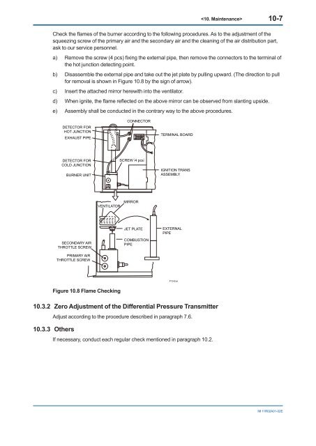
10-7Check the flames of the burner according to the following procedures. As to the adjustment of thesqueezing screw of the primary air and the secondary air and the cleaning of the air distribution part,ask to our service personnel.a) Remove the screw (4 pcs) fixing the external pipe, then remove the connectors to the terminal ofthe hot junction detecting point.b) Disassemble the external pipe and take out the jet plate by pulling upward. (The direction to pull<strong>for</strong> removal is shown in Figure 10.8 by the sign of arrow).c) Insert the attached mirror herewith into the ventilator.d) When ignite, the flame reflected on the above mirror can be observed from slanting upside.e) Assembly shall be conducted in the contrary way to the above procedures.DETECTOR FORHOT JUNCTIONEXHAUST PIPECONNECTORTERMINAL BOARDDETECTOR FORCOLD JUNCTIONBURNER UNITSCREW4 pcsIGNITION TRANSASSEMBLYVENTILATORMIRRORSECONDARY AIRTHROTTLE SCREWPRIMARY AIRTHROTTLE SCREWJET PLATECOMBUSTIONPIPEEXTERNALPIPEF10-9.aiFigure 10.8 Flame Checking10.3.2 Zero Adjustment of the Differential Pressure TransmitterAdjust according to the procedure described in paragraph 7.6.10.3.3 OthersIf necessary, conduct each regular check mentioned in paragraph 10.2.IM 11R02A01-02E


