Harmonic balance method for FEM analysis of fluid flow in a ...
Harmonic balance method for FEM analysis of fluid flow in a ...
Harmonic balance method for FEM analysis of fluid flow in a ...
You also want an ePaper? Increase the reach of your titles
YUMPU automatically turns print PDFs into web optimized ePapers that Google loves.
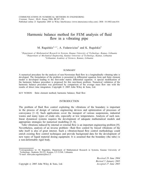
COMMUNICATIONS IN NUMERICAL METHODS IN ENGINEERINGCommun. Numer. Meth. Engng 2006; 22:347–356Published onl<strong>in</strong>e 21 September 2005 <strong>in</strong> Wiley InterScience (www.<strong>in</strong>terscience.wiley.com). DOI: 10.1002/cnm.816<strong>Harmonic</strong> <strong>balance</strong> <strong>method</strong> <strong>for</strong> <strong>FEM</strong> <strong>analysis</strong> <strong>of</strong> uidow <strong>in</strong> a vibrat<strong>in</strong>g pipeM. Ragulskis 1; ∗; † , A. Fedaravicius 2 and K. Ragulskis 31 Department <strong>of</strong> Mathematical Research <strong>in</strong> Systems; Kaunas University <strong>of</strong> Technology, Kaunas; Lithuania2 Department <strong>of</strong> Mechanical Eng<strong>in</strong>eer<strong>in</strong>g; Kaunas University <strong>of</strong> Technology; Kaunas; Lithuania3 Lithuanian Academy <strong>of</strong> Sciences; Kaunas; LithuaniaSUMMARYA numerical procedure <strong>for</strong> the <strong>analysis</strong> <strong>of</strong> non-Newtonian uid ow <strong>in</strong> a longitud<strong>in</strong>ally vibrat<strong>in</strong>g tube isdeveloped. The <strong>for</strong>mulation <strong>of</strong> the problem is presented <strong>in</strong> dierential equation <strong>for</strong>m and nite elementmodel is developed lead<strong>in</strong>g to the rst-order matrix dierential equation. A special modication <strong>of</strong>the harmonic <strong>balance</strong> procedure is proposed <strong>for</strong> this non-l<strong>in</strong>ear problem. Numerical validation <strong>of</strong> theharmonic <strong>balance</strong> procedure was per<strong>for</strong>med by comparison <strong>of</strong> the average mass ow rate with theresults <strong>of</strong> direct time <strong>in</strong>tegration. Copyright ? 2005 John Wiley & Sons, Ltd.KEY WORDS:nite element <strong>method</strong>; harmonic <strong>balance</strong>; uid owINTRODUCTIONThe problem <strong>of</strong> uid ow control exploit<strong>in</strong>g the vibrations <strong>of</strong> the boundary is important<strong>in</strong> the process <strong>of</strong> design <strong>of</strong> various eng<strong>in</strong>eer<strong>in</strong>g devices and optimization <strong>of</strong> processes <strong>of</strong>conveyance [1–4]. Such applications cover the transport <strong>of</strong> various suspensions, <strong>in</strong>dustrialwastes and many types <strong>of</strong> crude oils, especially at low temperatures. Analysis <strong>of</strong> such nonl<strong>in</strong>eardynamical systems requires the development <strong>of</strong> adequate mathematical models andappropriate strategies <strong>for</strong> numerical modell<strong>in</strong>g [5–8].Tube vibrations <strong>in</strong>duced by <strong>in</strong>ternal or external ow is an important eng<strong>in</strong>eer<strong>in</strong>g problem [9].Nevertheless, <strong>analysis</strong> <strong>of</strong> an <strong>in</strong>verse problem—uid ow control by <strong>for</strong>ced vibrations <strong>of</strong> thetube itself is also <strong>of</strong> great <strong>in</strong>terest. Such a vibration-based ow control <strong>method</strong>ology couldenrich exist<strong>in</strong>g ow control techniques and provide background data <strong>for</strong> the development <strong>of</strong>new types <strong>of</strong> liquid material dos<strong>in</strong>g equipment. It is assumed that the boundary (the tube) isa non-de<strong>for</strong>mable rigid body.∗ Correspondence to: M. Ragulskis, Department <strong>of</strong> Mathematical Research <strong>in</strong> Systems, Kaunas University <strong>of</strong>Technology, Studentu 50-222, Kaunas, LT-51368, Lithuania.† E-mail: m<strong>in</strong>vydas.ragulskis@ktu.LTReceived 28 June 2004Revised 5 January 2005Copyright ? 2005 John Wiley & Sons, Ltd. Accepted 27 June 2005
348 M. RAGULSKIS, A. FEDARAVICIUS AND K. RAGULSKISThe nite element <strong>for</strong>mulation is used together with the approximate procedure <strong>for</strong> the<strong>analysis</strong> <strong>of</strong> non-l<strong>in</strong>ear steady-state vibrations which consists from two basic steps. First anite element model is developed lead<strong>in</strong>g to the rst-order matrix dierential equation. Thenan approximate steady-state solution is sought us<strong>in</strong>g the proposed harmonic <strong>balance</strong> procedurewhich consists from the follow<strong>in</strong>g ma<strong>in</strong> steps:(1) problem <strong>for</strong>mulation <strong>in</strong> dierential equation <strong>for</strong>m;(2) development <strong>of</strong> the nite element problem <strong>for</strong>mulation;(3) modal decomposition <strong>of</strong> the solution;(4) development and application <strong>of</strong> the harmonic <strong>balance</strong> <strong>method</strong>.The harmonic <strong>balance</strong> <strong>method</strong> <strong>in</strong> general is one <strong>of</strong> the most straight<strong>for</strong>ward and practical<strong>method</strong>s <strong>for</strong> estimat<strong>in</strong>g periodic steady-state solutions and can be applied to non-l<strong>in</strong>ear equationswith a periodic <strong>for</strong>c<strong>in</strong>g term, thus provid<strong>in</strong>g better understand<strong>in</strong>g <strong>of</strong> the reasons <strong>for</strong> thenon-l<strong>in</strong>ear eects tak<strong>in</strong>g place <strong>in</strong> the system [10].A semi-analytical <strong>method</strong> <strong>for</strong> calculat<strong>in</strong>g a non-Newtonian uid ow <strong>in</strong> a vibrat<strong>in</strong>g pipe ispresented. The <strong>method</strong> uses an ecient harmonic <strong>balance</strong> approach to evaluate steady-stateuid ow elim<strong>in</strong>at<strong>in</strong>g the time <strong>in</strong>tegration.FINITE ELEMENT MODELA Cartesian coord<strong>in</strong>ate system is dened where the z-axis is parallel to the axis <strong>of</strong> the tube(Figure 1). It is assumed that the cross-section <strong>of</strong> the tube does not vary with the z coord<strong>in</strong>ateand the velocity <strong>of</strong> uid ow does not depend on z, i.e. w = w(x; y; t), where w denotes thevelocity and t the time. The other components <strong>of</strong> velocity are assumed to be equal to zero.Thus the condition <strong>of</strong> <strong>in</strong>compressibility is satised identically. The stresses take the <strong>for</strong>m x = y = z = −p; xy =0; yz = @w@y ;where p denotes the pressure and the viscosity <strong>of</strong> the uid. zx = @w@x(1)Figure 1. The pr<strong>in</strong>cipal model <strong>of</strong> the system.Copyright ? 2005 John Wiley & Sons, Ltd. Commun. Numer. Meth. Engng 2006; 22:347–356
HARMONIC BALANCE METHOD FOR FLUID FLOW 349The dynamic equilibrium equation <strong>in</strong> the direction <strong>of</strong> the z-axis can be written as(@ @w )+ @ ( @w )− @p + g = @w(2)@x @x @y @y @z @twhere is the density <strong>of</strong> the uid, g is the acceleration <strong>of</strong> gravity, and @p=@z the gradient<strong>of</strong> the pressure <strong>in</strong> the direction <strong>of</strong> the z-axis, is assumed constant along the tube. It is alsoassumed that the uid is non-Newtonian and that the viscosity is expressed as√ (@w ) 2 = 1 + 2 +@x( ) 2 @w(3)@ywhere 1 and 2 are constants. The non-Newtonian model given by Equation (3) presentsan approximation <strong>for</strong> the pseudoplastic model <strong>of</strong>ten used <strong>for</strong> the description <strong>of</strong> the non-l<strong>in</strong>earfeatures <strong>of</strong> suspensions [11].The wall boundary condition− @w@n = (w − w∗ ) (4)takes <strong>in</strong>to account the longitud<strong>in</strong>al vibration <strong>of</strong> the tube, where n is the outward normaldirection to the boundary <strong>of</strong> the cross-section <strong>of</strong> the ow <strong>in</strong>side the tube, is the coecient<strong>of</strong> slippage (slid<strong>in</strong>g friction between the uid and the surface <strong>of</strong> the tube) and w ∗ is thevelocity <strong>of</strong> the wall <strong>in</strong> the direction <strong>of</strong> the z-axis. It is assumed that the boundary per<strong>for</strong>msharmonic oscillations <strong>in</strong> the direction <strong>of</strong> the z-axis, so thatw ∗ = a s<strong>in</strong> !t (5)where a and ! denote the amplitude and the frequency <strong>of</strong> oscillations. The amplitude <strong>of</strong>k<strong>in</strong>ematic excitation <strong>of</strong> the boundary is a=!.It can be noted that, <strong>for</strong> the pipe <strong>of</strong> circular cross-section, the problem is axi-symmetricbut, bear<strong>in</strong>g <strong>in</strong> m<strong>in</strong>d that the results are applicable also <strong>for</strong> other tube shapes (to the tubes<strong>of</strong> other cross-sections), the 2D problem is solved. The cross-section <strong>of</strong> the ow is meshedus<strong>in</strong>g the nite element approximation. The result<strong>in</strong>g matrix dierential equation:[C]{ ˙} +[K]{} = {F} (6)is obta<strong>in</strong>ed on the basis <strong>of</strong> the Galerk<strong>in</strong> <strong>method</strong> <strong>of</strong> weighted residuals [11, 12]. <strong>FEM</strong> matricestake the <strong>for</strong>m:∫∫[C]= [N ] T [N ]dx dy∫∫[K]=∮[B] T 1 [B]dx dy + [M] T [M]ds∫∫ ({F}= [N] T∮+ [M] T w ∗ dsg − @p@z) ∫∫dx dy −√ (@w ) 2[B] T 2 +@x( ) 2 @w[B]{} dx dy@y(7)Copyright ? 2005 John Wiley & Sons, Ltd. Commun. Numer. Meth. Engng 2006; 22:347–356
350 M. RAGULSKIS, A. FEDARAVICIUS AND K. RAGULSKISwhere {} is the vector <strong>of</strong> nodal velocities. The upper dot <strong>in</strong> Equation (6) denotes dierentiationwith respect to time; s is the boundary l<strong>in</strong>e <strong>of</strong> the cross-section <strong>of</strong> the ow;[N]=[N 1 N 2 ··· N n ]⎡@N 1 @N 2···@x @x[B]=⎢⎣@N 1 @N 2···@y @y[M]=[M 1 M 2 ··· M m ]@N n@x@N n@y⎤⎥⎦(8)where N 1 ;N 2 ::: are the shape functions <strong>of</strong> the nite element <strong>in</strong> the cross-section <strong>of</strong> the ow,M 1 ;M 2 ::: are the shape functions <strong>of</strong> the nite element on the boundary <strong>of</strong> the cross-section<strong>of</strong> the ow.The nite element equations could be <strong>in</strong>tegrated <strong>in</strong> time and transient ow processes canbe analysed. Instead approximate <strong>method</strong>s <strong>of</strong> non-l<strong>in</strong>ear vibration theory are applied to thisproblem.HARMONIC BALANCE PROCEDUREFirst the eigenpairs <strong>of</strong> the homogeneous system [C]{ ˙}+[K]{} = 0 are determ<strong>in</strong>ed and modaldecomposition <strong>of</strong> Equation (6) is per<strong>for</strong>med [12]:[] T [C][]{Ż} + [] T [K][]{Z} = [] T {F} (9)where [] = [{ 1 } { 2 } :::];{ i } is the ith exponential decay eigenmode with correspond<strong>in</strong>geigenvalue i . Then the vector <strong>of</strong> velocities is expressed as⎧ ⎫z 1 ⎪⎨ ⎪⎬{} = []{Z} = [] z 2⎪⎩ ⎪⎭···where z i denote modal coecients <strong>for</strong> mode i.The determ<strong>in</strong>ation <strong>of</strong> the averaged surface <strong>of</strong> velocities is per<strong>for</strong>med by solv<strong>in</strong>g the follow<strong>in</strong>gfour successive problems.A. Steady-state harmonic solution. The s<strong>in</strong>usoidal variation <strong>of</strong> the wall velocity is assumedwhile the condition −(@p=@z)+g = 0 is be<strong>in</strong>g satised, and the steady-state harmonic motion<strong>of</strong> the l<strong>in</strong>ear system is obta<strong>in</strong>ed by solv<strong>in</strong>g the modal equations:(10)ddt (z i)+ i z i = f i (11)Copyright ? 2005 John Wiley & Sons, Ltd. Commun. Numer. Meth. Engng 2006; 22:347–356
HARMONIC BALANCE METHOD FOR FLUID FLOW 351where f i is the modal ⎧load<strong>in</strong>g ⎫ <strong>for</strong> mode i. It is assumed that {F} = {F s } s<strong>in</strong> !t. Then,{F s } = ∮ ⎪⎨ f[M] T 1s ⎪⎬a ds and f2⎪⎩s ···⎪⎭ = []T {F s }. Thus f i = fis s<strong>in</strong> !t, produc<strong>in</strong>gz i = zi s s<strong>in</strong> !t + zi c cos !t (12)The vectors <strong>of</strong> the s<strong>in</strong>e and cos<strong>in</strong>e components <strong>of</strong> the steady-state motion { s } and { c } arethen expressed like:⎧ ⎫⎧ ⎫z1⎪⎨s z1⎪⎬⎪⎨c ⎪⎬{ s } = [] z2s ; { c } = [] z2c (13)⎪⎩ ⎪⎭⎪⎩ ⎪⎭······The follow<strong>in</strong>g system <strong>of</strong> l<strong>in</strong>ear algebraic equations is solved <strong>for</strong> each eigenmode:[ ]{ } { }i −! zsi fsi=! i zic 0(14)B. Static solution. The static (constant <strong>in</strong> time) solution is obta<strong>in</strong>ed assum<strong>in</strong>g that the term−(@p=@z)+g is constant <strong>in</strong> time and the wall velocity is equal to zero, that is:∫∫ ({F 0 } = [N] T g − @p )dx dy (15)@zThis requires the solution <strong>of</strong> the system <strong>of</strong> l<strong>in</strong>ear algebraic equations:[K]{ 0 } = {F 0 } (16)⎧ ⎫⎪⎨ f10 ⎪⎬This solution aga<strong>in</strong> is sought us<strong>in</strong>g modal decomposition. Denot<strong>in</strong>g f2⎪⎩0⎪⎭ = []T {F 0 } and⎧ ⎫···⎪⎨ z10 ⎪⎬{ 0 } = [] z2⎪⎩0 , <strong>for</strong> each eigenmode we have:⎪⎭···zi 0 = f0 i(17) iUp to this po<strong>in</strong>t the Newtonian model <strong>of</strong> the uid is used as an approximation. The totalvelocities are:{(t)} = { 0 } + { s } s<strong>in</strong> !t + { c } cos !t (18)C. Averaged transverse velocities. The load vector is obta<strong>in</strong>ed <strong>in</strong> the process <strong>of</strong> assembly <strong>of</strong>the follow<strong>in</strong>g loads:(a) the load occurr<strong>in</strong>g from the constant term −(@p=@z)+g;(b) the non-l<strong>in</strong>ear term due to the static solution and the harmonic motion.Copyright ? 2005 John Wiley & Sons, Ltd. Commun. Numer. Meth. Engng 2006; 22:347–356
352 M. RAGULSKIS, A. FEDARAVICIUS AND K. RAGULSKISThose calculations are per<strong>for</strong>med <strong>for</strong> a number <strong>of</strong> discrete moments equally spaced dur<strong>in</strong>gthe period. Time average <strong>of</strong> load vector takes the <strong>for</strong>m:√∫∫ ({F 1 } = [N] T g − @p ) ∫∫ (@w ) 2dx dy − [B]@zT 2 +@x⎛ √∫∫ (= [N] T g − @p )dx dy − 1 ∫∫ √√√ (m∑ ⎜@w⎝ [B] T 2@z m i=1@x( ) 2m (i − 1){× [B] { 0 } + { s } s<strong>in</strong>( ) 2 @w[B]{} dx dy@y) 2 ( ) 2@w∣ +t=ti@y ∣t=ti⎞( )}2+ { c } cosm (i − 1) dx dy⎠ (19)where the upper dash denotes time average; !t =(2=m)(i − 1);⎧@w⎪⎨ @x ∣⎫⎪t=ti⎬ {( ) ( )}2 2 =[B] {@w0 } + { s } s<strong>in</strong>m (i − 1) + { c } cosm (i − 1) ⎪⎩⎪@y ∣ ⎭t=ti(20)m is the number <strong>of</strong> discrete time moments <strong>in</strong> a period.F<strong>in</strong>ally, the non-l<strong>in</strong>ear problem is solved obta<strong>in</strong><strong>in</strong>g the averaged surface <strong>of</strong> velocities us<strong>in</strong>gpreviously described technique <strong>of</strong> modal decomposition <strong>for</strong> the solution <strong>of</strong> the system <strong>of</strong> l<strong>in</strong>earalgebraic equations:[K]{ 1 } = {F 1 } (21)D. Mass ow rate. F<strong>in</strong>ally, the average mass ow rate is found by <strong>in</strong>tegrat<strong>in</strong>g over thecross-sectional area:∫∫Q = w(x; y)dx dy (22)where w(x; y) are the averaged transverse velocities which are calculated from { 1 } by us<strong>in</strong>gthe shape functions <strong>of</strong> the appropriate nite elements. It is assumed that the averag<strong>in</strong>g <strong>in</strong>tervalis much longer than the period <strong>of</strong> oscillations.NUMERICAL RESULTSCross-section <strong>of</strong> the tube is assumed to be a circle and one-fourth <strong>of</strong> it is analysed (Figure 2).The characteristics <strong>of</strong> the non-Newtonian uid represent a liquid-type suspension ( 1 =0:004g=mm s = 4 cP, 2 = − 0:0001 g=mm, =0:04 g=mm 2 s, =0:001 g=mm 3 , −(@p=@z) +g =0:003 g=mm 2 s 2 ). Radius <strong>of</strong> the tube is R = 10 mm; number <strong>of</strong> moments <strong>in</strong> the period used <strong>for</strong>Copyright ? 2005 John Wiley & Sons, Ltd. Commun. Numer. Meth. Engng 2006; 22:347–356
354 M. RAGULSKIS, A. FEDARAVICIUS AND K. RAGULSKISFigure 3. Numerical validation <strong>of</strong> the harmonic <strong>balance</strong> procedure.Figure 4. Relationship between the mass ow rate Q(g=s) and the amplitude <strong>of</strong> excitation a=! (mm) atvarious frequencies <strong>of</strong> excitation ! i =(i − 1) · 0; 2; i =1;:::;21.the cost <strong>of</strong> numerical <strong>in</strong>tegration over one time step is W; the calculation <strong>of</strong> the mass owrate is per<strong>for</strong>med <strong>for</strong> each time step at a cost w; m time steps <strong>in</strong> a period <strong>of</strong> excitation areused; 10 periods are required to achieve steady-state motion, the cost <strong>of</strong> numerical <strong>in</strong>tegrationcan be approximated as 10m(W + w).Copyright ? 2005 John Wiley & Sons, Ltd. Commun. Numer. Meth. Engng 2006; 22:347–356
HARMONIC BALANCE METHOD FOR FLUID FLOW 355The costs <strong>of</strong> the stages <strong>of</strong> the harmonic <strong>balance</strong> procedure <strong>for</strong> the same problem can beapproximated:A. Steady-state harmonic solution—cost is W (comparable with one time step <strong>for</strong> the samemesh<strong>in</strong>g).B. Static solution—cost is W=2 (about 50% <strong>of</strong> the cost <strong>of</strong> harmonic solution).C. Determ<strong>in</strong>ation <strong>of</strong> the averaged transverse velocities—cost is mW=2 (m is the number <strong>of</strong>discrete time moments <strong>in</strong> a period <strong>of</strong> excitation);D. Determ<strong>in</strong>ation <strong>of</strong> the average mass ow rate—cost is w.Thus the total cost <strong>of</strong> the proposed harmonic <strong>balance</strong> procedure is ((3 + m)=2) · W + w. Forrealistic mesh<strong>in</strong>gs w can be approximated as 0:1 W . So the cost <strong>of</strong> the proposed harmonic<strong>balance</strong> procedure is about twenty times lower than that <strong>of</strong> numerical time <strong>in</strong>tegration. Numericalexperiments <strong>in</strong>dicate that the proposed harmonic <strong>balance</strong> procedure produces resultswhich <strong>in</strong> some cases can dier by about 10% from the ‘exact’ ones obta<strong>in</strong>ed from numerical<strong>in</strong>tegration.The problem <strong>for</strong> which the harmonic <strong>balance</strong> procedure was developed is typical <strong>for</strong> thetransportation <strong>of</strong> uid and there<strong>for</strong>e should be regarded as a demonstrational problem <strong>for</strong>develop<strong>in</strong>g the algorithm. The potential <strong>of</strong> the <strong>method</strong> lies <strong>in</strong> its possible applications to thethree dimensional non-l<strong>in</strong>ear problems <strong>of</strong> computational uid dynamics.CONCLUSIONSNumerical model describ<strong>in</strong>g ow <strong>of</strong> non-Newtonian uid <strong>in</strong> a tube per<strong>for</strong>m<strong>in</strong>g longitud<strong>in</strong>alvibrations is developed. It must be noted that this model <strong>in</strong>corporates non-l<strong>in</strong>earity and representsthe dynamic behaviour <strong>of</strong> the liquid suspension. The <strong>in</strong>ertia <strong>of</strong> the uid is taken <strong>in</strong>toaccount and <strong>FEM</strong> damp<strong>in</strong>g matrix is obta<strong>in</strong>ed. The velocity <strong>of</strong> the longitud<strong>in</strong>al motion <strong>of</strong>the walls is taken <strong>in</strong>to account through the boundary condition and thus is directly <strong>in</strong>corporated<strong>in</strong>to the nite element <strong>for</strong>mulation. <strong>Harmonic</strong> <strong>balance</strong> <strong>method</strong> <strong>for</strong> determ<strong>in</strong>ation <strong>of</strong>averaged transverse velocities <strong>of</strong> non-Newtonian uid is proposed. The results <strong>of</strong> the <strong>analysis</strong>show that the longitud<strong>in</strong>al tube vibrations can be eectively applied <strong>for</strong> uid ow control and<strong>in</strong>corporated <strong>in</strong>to the design <strong>of</strong> vibration spray<strong>in</strong>g and dos<strong>in</strong>g devices <strong>of</strong> various substances.REFERENCES1. Hui L, Tomita Y. A numerical simulation <strong>of</strong> swirl<strong>in</strong>g ow pneumatic convey<strong>in</strong>g <strong>in</strong> a horizontal pipel<strong>in</strong>e.Particulate Science and Technology: An International Journal 2000; 18(4):275–292.2. Hauser G, Sommer K. Plug ow type pneumatic convey<strong>in</strong>g <strong>of</strong> abrasive products <strong>in</strong> food <strong>in</strong>dustry. Journal <strong>of</strong>Powder and Bulk Solids Technology 1998; 12:511–519.3. Bubulis A, Ragulskis L. Dry substances transportation and dos<strong>in</strong>g us<strong>in</strong>g vibrations. 41 InternationalesWissenchaftliches Kolloquium, Ilmenau, 1996; 492–496.4. Ragulskis M, Palevicius A. Theoretical and experimental studies <strong>of</strong> tubular valve dynamics. InternationalJournal <strong>of</strong> Acoustics and Vibration 2002; 7(1):53–57.5. Morgan K, Peraire J. Unstructured grid nite element <strong>method</strong>s <strong>for</strong> uid dynamics. Reports on Progress <strong>in</strong>Physics 1998; 61(6):569–638.6. Thomasset F. Implementation <strong>of</strong> F<strong>in</strong>ite Element Methods <strong>for</strong> Navier–Stokes Equations. Spr<strong>in</strong>ger: Germany,1981; 159.7. Blawzdziewicz J, Feuillebois F. Calculation <strong>of</strong> an eective slip <strong>in</strong> a settl<strong>in</strong>g suspension at a vertical wall.International Journal <strong>of</strong> Fluid Mechanics Research 1995; 22(1):164–169.8. Baker AJ. F<strong>in</strong>ite Element Computational Fluid Mechanics. Hemisphere PC: U.S.A., 1983; 510.Copyright ? 2005 John Wiley & Sons, Ltd. Commun. Numer. Meth. Engng 2006; 22:347–356
356 M. RAGULSKIS, A. FEDARAVICIUS AND K. RAGULSKIS9. Huang Y, Hsu C. Dynamic behaviour <strong>of</strong> tubes subjected to <strong>in</strong>ternal and external cross ows. Journal <strong>of</strong> Shockand Vibration 1997; 4(2):77–91.10. Jordan DW, Smith P. Nonl<strong>in</strong>ear Ord<strong>in</strong>ary Dierential Equations. Ox<strong>for</strong>d University Press: U.K., 1999; 550.11. Rao SS. The F<strong>in</strong>ite Element Method <strong>in</strong> Eng<strong>in</strong>eer<strong>in</strong>g. Pergamon Press: U.K., 1982; 625.12. Zienkiewicz OC, Morgan K. F<strong>in</strong>ite Elements and Approximation. Mir: Moscow, 1986; 320.13. Hearn D, Baker MP. Computer Graphics. Prentice-Hall International: U.S.A., 1986; 351.Copyright ? 2005 John Wiley & Sons, Ltd. Commun. Numer. Meth. Engng 2006; 22:347–356


