Modelling Human Factors using the Systems Modelling Language
Modelling Human Factors using the Systems Modelling Language
Modelling Human Factors using the Systems Modelling Language

Create successful ePaper yourself
Turn your PDF publications into a flip-book with our unique Google optimized e-Paper software.
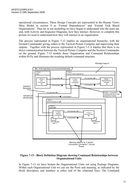
HFIDTC/2/WP2.8.9/1Version 2/ 24th September 2008operational circumstances. These Design Concepts are represented in <strong>the</strong> <strong>Human</strong> ViewsMeta Model in section 9 as ‘Formal Dependencies’ and ‘Formal Task BasedOrganisations’. Thus far in our modelling we have begun to understand who <strong>the</strong> users areand, with Activity and Sequence Diagrams, how <strong>the</strong>y interact. However, to complete thispicture we need to understand how <strong>the</strong>y will interact as an organisation.The process represented in Figure 7-12 implies an organisational hierarchy, with <strong>the</strong>Ground Commander giving orders to <strong>the</strong> Tactical Picture Compiler and supervising <strong>the</strong>iroutputs. Toge<strong>the</strong>r with <strong>the</strong> process represented in Figure 7-5 it implies that <strong>the</strong>re is nodirect communication between <strong>the</strong> Tactical Picture Compiler and <strong>the</strong> Section Commanderon <strong>the</strong> ground. Figure 7-13 models those Organisation and Command Relationshipswithin H-Fly and illustrates <strong>the</strong> resulting default command structure.Figure 7-13 - Block Definition Diagram showing Command Relationships betweenOrganisational UnitsIn Figure 7-13 we have broken <strong>the</strong> Organisational Units out <strong>using</strong> Package Diagrams.Within each Organisational Unit we can see <strong>the</strong> Posts and manning, as indicated by <strong>the</strong>block descriptors and numbers at ei<strong>the</strong>r end of <strong>the</strong> relational lines. The Command32