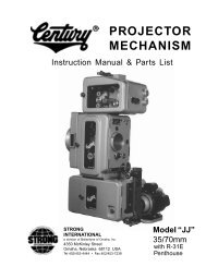
PREFACE THE STRONG HIGHLIGHT II Xenon ... - Iceco.com
PREFACE THE STRONG HIGHLIGHT II Xenon ... - Iceco.com
PREFACE THE STRONG HIGHLIGHT II Xenon ... - Iceco.com

You also want an ePaper? Increase the reach of your titles
YUMPU automatically turns print PDFs into web optimized ePapers that Google loves.
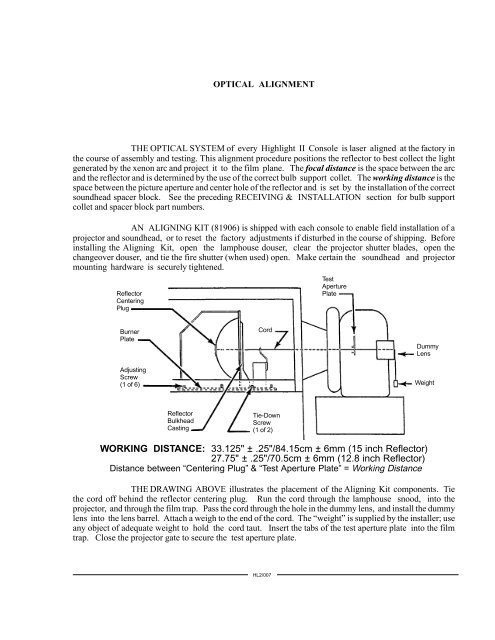
OPTICAL ALIGNMENT<strong>THE</strong> OPTICAL SYSTEM of every Highlight <strong>II</strong> Console is laser aligned at the factory inthe course of assembly and testing. This alignment procedure positions the reflector to best collect the lightgenerated by the xenon arc and project it to the film plane. The focal distance is the space between the arcand the reflector and is determined by the use of the correct bulb support collet. The working distance is thespace between the picture aperture and center hole of the reflector and is set by the installation of the correctsoundhead spacer block. See the preceding RECEIVING & INSTALLATION section for bulb supportcollet and spacer block part numbers.AN ALIGNING KIT (81906) is shipped with each console to enable field installation of aprojector and soundhead, or to reset the factory adjustments if disturbed in the course of shipping. Beforeinstalling the Aligning Kit, open the lamphouse douser, clear the projector shutter blades, open thechangeover douser, and tie the fire shutter (when used) open. Make certain the soundhead and projectormounting hardware is securely tightened.ReflectorCenteringPlugTestAperturePlateBurnerPlateAdjustingScrew(1 of 6)CordDummyLensWeightReflectorBulkheadCastingTie-DownScrew(1 of 2)WORKING DISTANCE: 33.125" ± .25"/84.15cm ± 6mm (15 inch Reflector)27.75" ± .25"/70.5cm ± 6mm (12.8 inch Reflector)Distance between “Centering Plug” & “Test Aperture Plate” = Working Distance<strong>THE</strong> DRAWING ABOVE illustrates the placement of the Aligning Kit <strong>com</strong>ponents. Tiethe cord off behind the reflector centering plug. Run the cord through the lamphouse snood, into theprojector, and through the film trap. Pass the cord through the hole in the dummy lens, and install the dummylens into the lens barrel. Attach a weigh to the end of the cord. The “weight” is supplied by the installer; useany object of adequate weight to hold the cord taut. Insert the tabs of the test aperture plate into the filmtrap. Close the projector gate to secure the test aperture plate.HL2/007