

Advances in the Modelling of Motorcycle Dynamics - ResearchGate
Advances in the Modelling of Motorcycle Dynamics - ResearchGate
Advances in the Modelling of Motorcycle Dynamics - ResearchGate

Create successful ePaper yourself
Turn your PDF publications into a flip-book with our unique Google optimized e-Paper software.
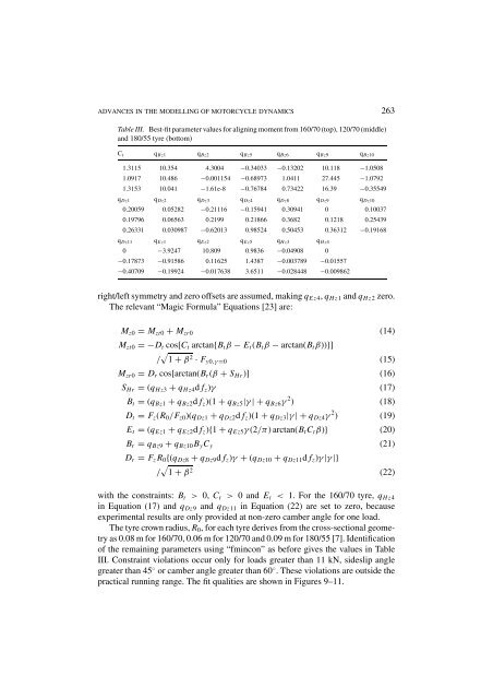
ADVANCES IN THE MODELLING OF MOTORCYCLE DYNAMICS 263Table III. Best-fit parameter values for align<strong>in</strong>g moment from 160/70 (top), 120/70 (middle)and 180/55 tyre (bottom)C t q Bz1 q Bz2 q Bz5 q Bz6 q Bz9 q Bz101.3115 10.354 4.3004 −0.34033 −0.13202 10.118 −1.05081.0917 10.486 −0.001154 −0.68973 1.0411 27.445 −1.07921.3153 10.041 −1.61e-8 −0.76784 0.73422 16.39 −0.35549q Dz1 q Dz2 q Dz3 q Dz4 q Dz8 q Dz9 q Dz100.20059 0.05282 −0.21116 −0.15941 0.30941 0 0.100370.19796 0.06563 0.2199 0.21866 0.3682 0.1218 0.254390.26331 0.030987 −0.62013 0.98524 0.50453 0.36312 −0.19168q Dz11 q Ez1 q Ez2 q Ez5 q Hz3 q Hz40 −3.9247 10.809 0.9836 −0.04908 0−0.17873 −0.91586 0.11625 1.4387 −0.003789 −0.01557−0.40709 −0.19924 −0.017638 3.6511 −0.028448 −0.009862right/left symmetry and zero <strong>of</strong>fsets are assumed, mak<strong>in</strong>g q Ez4 , q Hz1 and q Hz2 zero.The relevant “Magic Formula” Equations [23] are:M z0 = M zt0 + M zr0 (14)M zt0 =−D t cos[C t arctan{B t β − E t (B t β − arctan(B t β))}]/ √ 1 + β 2 · F y0,γ =0 (15)M zr0 = D r cos[arctan(B r (β + S Hr )] (16)S Hr = (q Hz3 + q Hz4 d f z )γ (17)B t = (q Bz1 + q Bz2 d f z )(1 + q Bz5 |γ |+q Bz6 γ 2 ) (18)D t = F z (R 0 /F z0 )(q Dz1 + q Dz2 d f z )(1 + q Dz3 |γ |+q Dz4 γ 2 ) (19)E t = (q Ez1 + q Ez2 d f z ){1 + q Ez5 γ (2/π) arctan(B t C t β)} (20)B r = q Bz9 + q Bz10 B y C y (21)D r = F z R 0 {(q Dz8 + q Dz9 d f z )γ + (q Dz10 + q Dz11 d f z )γ |γ |}/ √ 1 + β 2 (22)with <strong>the</strong> constra<strong>in</strong>ts: B t > 0, C t > 0 and E t < 1. For <strong>the</strong> 160/70 tyre, q Hz4<strong>in</strong> Equation (17) and q Dz9 and q Dz11 <strong>in</strong> Equation (22) are set to zero, becauseexperimental results are only provided at non-zero camber angle for one load.The tyre crown radius, R 0 , for each tyre derives from <strong>the</strong> cross-sectional geometryas 0.08 m for 160/70, 0.06 m for 120/70 and 0.09 m for 180/55 [7]. Identification<strong>of</strong> <strong>the</strong> rema<strong>in</strong><strong>in</strong>g parameters us<strong>in</strong>g “fm<strong>in</strong>con” as before gives <strong>the</strong> values <strong>in</strong> TableIII. Constra<strong>in</strong>t violations occur only for loads greater than 11 kN, sideslip anglegreater than 45 ◦ or camber angle greater than 60 ◦ . These violations are outside <strong>the</strong>practical runn<strong>in</strong>g range. The fit qualities are shown <strong>in</strong> Figures 9–11.


