Advances in the Modelling of Motorcycle Dynamics - ResearchGate
Advances in the Modelling of Motorcycle Dynamics - ResearchGate
Advances in the Modelling of Motorcycle Dynamics - ResearchGate
Create successful ePaper yourself
Turn your PDF publications into a flip-book with our unique Google optimized e-Paper software.
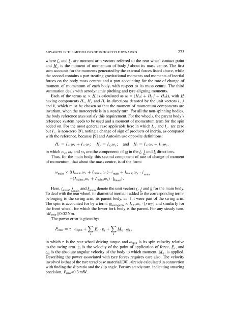
ADVANCES IN THE MODELLING OF MOTORCYCLE DYNAMICS 273where l i and l j are moment arm vectors referred to <strong>the</strong> rear wheel contact po<strong>in</strong>tand H j is <strong>the</strong> moment <strong>of</strong> momentum <strong>of</strong> body j about its mass centre. The firstsum accounts for <strong>the</strong> moments generated by <strong>the</strong> external forces listed above, while<strong>the</strong> second conta<strong>in</strong>s a part treat<strong>in</strong>g gravitational moments and moments <strong>of</strong> <strong>in</strong>ertialforces on <strong>the</strong> body mass centres and a part account<strong>in</strong>g for <strong>the</strong> rate <strong>of</strong> change <strong>of</strong>moment <strong>of</strong> momentum <strong>of</strong> each body, with respect to its mass centre. The thirdsummation deals with aerodynamic pitch<strong>in</strong>g and tyre align<strong>in</strong>g moments.Each <strong>of</strong> <strong>the</strong> terms w × H is calculated as w × (H x i + H y j + H z k), with Hhav<strong>in</strong>g components H x , H y and H z <strong>in</strong> directions denoted by <strong>the</strong> unit vectors i, jand k, which must be chosen so that <strong>the</strong> moment <strong>of</strong> momentum components are<strong>in</strong>variant, when <strong>the</strong> motorcycle is <strong>in</strong> a steady turn. For all <strong>the</strong> non-sp<strong>in</strong>n<strong>in</strong>g bodies,<strong>the</strong> body reference axes satisfy this requirement. For <strong>the</strong> wheels, <strong>the</strong> parent body’sreference system needs to be used and a moment <strong>of</strong> momentum term for <strong>the</strong> sp<strong>in</strong>added on. For <strong>the</strong> most general case applicable here <strong>in</strong> which I xy and I yz are zerobut I xz is non-zero [9], not<strong>in</strong>g a change <strong>of</strong> sign <strong>of</strong> products <strong>of</strong> <strong>in</strong>ertia, as comparedwith <strong>the</strong> reference, because [9] and Autosim use opposite def<strong>in</strong>itions:H x = I xx ω x + I xz ω z ; H y = I yy ω y ; and H z = I xz ω x + I zz ω z ,<strong>in</strong> which ω x , ω y and ω z are <strong>the</strong> components <strong>of</strong> ω <strong>in</strong> <strong>the</strong> i, j and k directions.Thus, for <strong>the</strong> ma<strong>in</strong> body, this second component <strong>of</strong> rate <strong>of</strong> change <strong>of</strong> moment<strong>of</strong> momentum, that about <strong>the</strong> mass centre, is <strong>of</strong> <strong>the</strong> form:ω ma<strong>in</strong> ×{(I ma<strong>in</strong>x ω x + I ma<strong>in</strong>xz ω z ) · i ma<strong>in</strong>+ I ma<strong>in</strong>y ω y · j ma<strong>in</strong>+(I ma<strong>in</strong>xz ω x + I ma<strong>in</strong>z ω z ) · k ma<strong>in</strong>}.Here, i ma<strong>in</strong>, j ma<strong>in</strong>and k ma<strong>in</strong>denote <strong>the</strong> unit vectors i, j and k for <strong>the</strong> ma<strong>in</strong> body.To deal with <strong>the</strong> rear wheel, its diametral <strong>in</strong>ertia is added to <strong>the</strong> correspond<strong>in</strong>g termsbelong<strong>in</strong>g to <strong>the</strong> sw<strong>in</strong>g arm, its parent body, as if it were part <strong>of</strong> <strong>the</strong> sw<strong>in</strong>g arm.The sp<strong>in</strong> is accounted for by a term: ω sw<strong>in</strong>garm × I rwy ω y · [rwy] and similarly for<strong>the</strong> front wheel, for which <strong>the</strong> lower fork body is <strong>the</strong> parent. For any steady turn,|M error |〈0.02 Nm.The power error is given by:P error = τ · ω sp<strong>in</strong> + ∑ iF i · v i + ∑ kM k · ω k ,<strong>in</strong> which τ is <strong>the</strong> rear wheel driv<strong>in</strong>g torque and ω sp<strong>in</strong> is its sp<strong>in</strong> velocity relativeto <strong>the</strong> sw<strong>in</strong>g arm. v i is <strong>the</strong> velocity <strong>of</strong> <strong>the</strong> po<strong>in</strong>t <strong>of</strong> application <strong>of</strong> force, F i , andω k is <strong>the</strong> absolute angular velocity <strong>of</strong> <strong>the</strong> body to which moment, M k ,isapplied.Describ<strong>in</strong>g <strong>the</strong> power associated with tyre forces requires care also. The velocity<strong>in</strong>volved is that <strong>of</strong> <strong>the</strong> tyre tread base material [30], already calculated <strong>in</strong> connectionwith f<strong>in</strong>d<strong>in</strong>g <strong>the</strong> slip ratio and <strong>the</strong> slip angle. For any steady turn, <strong>in</strong>dicat<strong>in</strong>g amaz<strong>in</strong>gprecision, P error 〈0.3 mW.


