QUICK DISCONNECT COUPLINGS - Duncan Rogers
QUICK DISCONNECT COUPLINGS - Duncan Rogers
QUICK DISCONNECT COUPLINGS - Duncan Rogers

You also want an ePaper? Increase the reach of your titles
YUMPU automatically turns print PDFs into web optimized ePapers that Google loves.
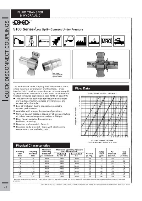
FLUID TRANSFER& HYDRAULIC<strong>QUICK</strong> <strong>DISCONNECT</strong> <strong>COUPLINGS</strong>5100 Series/Low Spill—Connect Under PressureThe 5100 Series brass coupling with steel tubular valveoffers minimum air inclusion and fluid loss. Threadtogether latch provides connect under pressure capabilityand vibration resistance. It is not rated for continuoushydraulic impulse applications. (See FD86 on page 69.)• Tubular valve construction for virtually no fluid lossduring disconnection, reduces environmental andworker safety hazards.• Low air inclusion during connection maintainssystem performance.• Available with wing or hex nut configurations.• Connect against pressure capability allows connectingof halves even when pressurized up to 500 psi.• Steel flange available for accessiblebulkhead mounting.• Standard seal material – Buna-N.• Standard body material – Brass with steel valvingcomponents, hex and wing nuts.Flow DataPhysical CharacteristicsCoupling CouplingMaximum Maximum Operating PressureOperating (psi disconnected) Rated Air FluidDash Interface Pressure* Male Half Female Half Vacuum Flow Inclusion LossSize Size (psi connected) S2 and S4 S5 (in./Hg.) (gpm) (cc max.) (cc max.)–4 –4 3000 3000 3000 28 4 .03 .01–6 –8 3000 3000 3000 28 7 .05 .06–8 –8 3000 3000 3000 28 7 .05 .10–10 –12 3000 3000 3000 28 18 .14 .10–12 –12 3000 3000 3000 28 18 .34 .26–16 –16 3000 3000 3000 28 40 .50 .35–20 –20 2750 2500 2750 28 75 .68 .70–24 –24 2500 2500 2000 28 100 .60 .94*Minimum burst pressure is equal to three times the maximum operating pressure. Not recommended for continuous hydraulic impulse applications at maximum operatingpressures.49This page is part of a complete catalog which contains technical and safety data that must be reviewed when selecting a product.
FLUID TRANSFER& HYDRAULIC5100 Series Coupling ThreadDimensional Data Part Number LineSize Size (P) A B 1 2 Buna-N Viton EPR Ref.Male Half/Less Flange –4 1 /8 -27 1.88 .90 .69 5100–S2–4B 1Female Pipe–6 1 /4 -18 2.58 1.07 .94 5100–S2–6B 2–8 3 /8 -18 2.58 1.07 .94 5100–S2–8B 3–10 1 /2 -14 3.11 1.38 1.19 5100–S2–10B 4–12 3 /4 -14 3.11 1.38 1.19 5100–S2–12B 5–16 1-11 1 / 2 3.55 1.76 1.56 5100–S2–16B 6–20 1 1 / 4 -11 1 / 2 3.71 2.10 1.88 5100–S2–20B 7–24 1 1 / 2 -11 1 / 2 4.12 2.48 2.19 5100–S2–24B 8Male Half/With Flange –4 1 /8 -27 1.88 .90 .94 5100–S4–4B 9Female Pipe–6 1 /4 -18 2.58 1.07 1.12 5100–S4–6B 10–8 3 /8 -18 2.58 1.07 1.12 5100–S4–8B 11–10 1 /2 -14 3.11 1.38 1.62 5100–S4–10B 12–12 3 /4 -14 3.11 1.38 1.62 5100–S4–12B 13–16 1-11 1 / 2 3.55 1.76 1.88 5100–S4–16B 14–20 1 1 / 4 -11 1 / 2 3.71 2.10 2.12 5100–S4–20B 15–24 1 1 / 2 -11 1 / 2 4.12 2.48 2.50 5100–S4–24B 16Female Half/Wing Nut –4 1 /8 -27 1.97 3.03 .56 5100–S5–4B 17Female Pipe–6 1 /4 -18 2.37 3.44 .76 5100–S5–6B 18–8 3 /8 -18 2.37 3.44 .76 5100–S5–8B 19–10 1 /2 -14 3.09 4.06 1.16 5100–S5–10B 20–12 3 /4 -14 3.09 4.06 1.16 5100–S5–12B 21–16 1-11 1 / 2 3.67 4.38 1.44 5100–S5–16B 22–20 1 1 / 4 -11 1 / 2 3.98 5.19 1.78 5100–S5–20B 23–24 1 1 / 2 -11 1 / 2 4.02 5.31 2.00 5100–S5–24B 24Female Half/Hex Nut –4 1 /8 -27 2.10 1.32 .56 1.19 5110–S5–4B 25Female Pipe–6 1 /4 -18 2.40 1.53 .76 1.38 5110–S5–6B 26–8 3 /8 -18 2.40 1.53 .76 1.38 5110–S5–8B 27–10 1 /2 -14 3.07 1.98 1.16 1.75 5110–S5–10B 28–12 3 /4 -14 3.07 1.98 1.16 1.75 5110–S5–12B 29–16 1-11 1 / 2 3.68 2.41 1.44 2.12 5110–S5–16B 30–20 1 1 / 4 -11 1 / 2 4.00 2.81 1.78 2.50 5110–S5–20B 31–24 1 1 / 2 -11 1 / 2 4.10 3.10 2.00 2.75 5110–S5–24B 32Complete Coupling –4 1 /8 -27 3.20 5101–4B 33Less Flange/With Wing Nut/Female Pipe–6 1 /4 -18 4.11 5101–6B 34–8 3 /8 -18 4.11 5101–8B 35–10 1 /2 -14 5.21 5101–10B 36–12 3 /4 -14 5.21 5101–12B 37–16 1-11 1 / 2 5.98 5101–16B 38–20 1 1 / 4 -11 1 / 2 6.31 5101–20B 39–24 1 1 / 2 -11 1 / 2 6.52 5101–24B 40Repair Kit –4 FF098–04 41Each kit will repair male and femalehalves.For component part number breakdown and service instructions, request bulletin JB41.–6, –8 FF098–08 42–10, –12 FF098–12 43–16 FF098–16 44–20 FF098–20 45–24 FF098–24 46<strong>QUICK</strong> <strong>DISCONNECT</strong> <strong>COUPLINGS</strong>This page is part of a complete catalog which contains technical and safety data that must be reviewed when selecting a product.50
FLUID TRANSFER& HYDRAULIC<strong>QUICK</strong> <strong>DISCONNECT</strong> <strong>COUPLINGS</strong>Dust Capwith Chain**6 Bolt Flange*5100 Series Coupling ThreadEach kit will repair male andfemale halves.Dust Plugwith Chain**For component part number breakdown and service instructions, request bulletin JB41.Dimensional Data Part Number LineSize Size (P) A B 1 2 Buna-N Viton EPR Ref.Complete Coupling –4 1 /8 -27 3.24 5100–4B 1With Flange/With Wing Nut/Female Pipe–6 1 /4 -18 4.11 5100–6B 2–8 3 /8 -18 4.11 5100–8B 3–10 1 /2 -14 5.21 5100–10B 4–12 3 /4 -14 5.21 5100–12B 5–16 1-11 1 / 2 5.99 5100–16B 6–20 1 1 / 4 -11 1 / 2 6.33 5100–20B 7–24 1 1 / 2 -11 1 / 2 6.54 5100–24B 8Complete Coupling –4 1 /8 -27 3.20 5111–4B 9Less Flange/With Hex Nut/Female Pipe–6 1 /4 -18 4.11 5111–6B 10–8 3 /8 -18 4.11 5111–8B 11–10 1 /2 -14 5.21 5111–10B 12–12 3 /4 -14 5.21 5111–12B 13–16 1-11 1 / 2 5.98 5111–16B 14–20 1 1 / 4 -11 1 / 2 6.31 5111–20B 15–24 1 1 / 2– -11 1 / 2 6.52 5111–24B 16Complete Coupling –4 1 /8 -27 3.20 5110–4B 17With Flange/With Hex Nut/Female Pipe–6 1 /4 -18 4.11 5110–6B 18–8 3 /8 -18 4.11 5110–8B 19–10 1 /2 -14 5.21 5110–10B 20–12 3 /4 -14 5.21 5110–12B 21–16 1-11 1 / 2 5.98 5110–16B 22–20 1 1 / 4 -11 1 / 2 6.31 5110–20B 23–24 1 1 / 2 -11 1 / 2 6.52 5110–24B 24Repair Kit –4 FF098–04 25–6, –8 FF098–08 26–10, –12 FF098–12 27–16 FF098–16 28–20 FF098–20 29–24 FF098–24 30Accessories Dust Cap with Chain Dust Plug with Chain 6 Bolt Flange 31–4 5100–S7–5 5100–S9–5 32–6, –8 5100–S7–8 5100–S9–8 33–10, –12 5100–S7–12 5100–S9–12 34–16 5100–S7–16 5100–S9–16 35–20 5100–S7–20 5100–S9–20 36–24 5100–S7–24 5100–S9–24 37–4 .201 1.44 150–22–5 40–6, –8 .201 1.69 150–22–8 41–10, –12 .201 2.12 150–22–12 42–16 .201 2.38 150–22–16 43–20 .201 2.62 150–22–20 44–24 .201 3.25 5100–22–24S 453839*6 Bolt Flange-holes equally spaced. (See “A” for bolt hole diameter, and “B” for bolt circle diameter).**To order caps and plugs without chain, order cap by part number 5100-32-(size) and plug by part number 5100-41-(size).51This page is part of a complete catalog which contains technical and safety data that must be reviewed when selecting a product.