Types 1078-1 / 1078-2 - Duncan Rogers
Types 1078-1 / 1078-2 - Duncan Rogers
Types 1078-1 / 1078-2 - Duncan Rogers
- No tags were found...

Create successful ePaper yourself
Turn your PDF publications into a flip-book with our unique Google optimized e-Paper software.
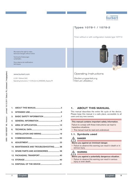
<strong>Types</strong> <strong>1078</strong>-1 / <strong>1078</strong>-2Timer without or with configuration module type 1077-2We reserve the right to maketechnical changes without notice.Technische Änderungenvorbehalten.Sous réserve de modificationstechniques.www.burkert.com© 2011 Bürkert SASOperating Instructions 1112/00_EU-ml_00563282_Original_FROperating InstructionsBedienungsanleitungManuel utilisateur1. ABOUT THIS MANUAL ...........................................................32. INTENDED USE ..........................................................................53. BASIC SAFETY INFORMATION .........................................74. GENERAL INFORMATION .....................................................95. AREA OF APPLICATION ...................................................... 106. TECHNICAL DATA .................................................................. 147. INSTALLATION AND WIRING ........................................... 198. COMMISSIONING .................................................................. 229. ADJUSTMENT ........................................................................... 2310. MAINTENANCE AND TROUBLESHOOTING ............ 3811. SPARE PARTS AND ACCESSORIES ........................... 3912. PACKAGING, TRANSPORT ............................................... 4013. STORAGE ................................................................................... 4014. DISPOSAL OF THE DEVICE ............................................. 411. ABOUT THIS MANUALThis manual describes the entire life cycle of the device.Please keep this manual in a safe place, accessible to allusers and any new owners.This manual contains important safety information.Failure to comply with these instructions can lead tohazardous situations.• This manual must be read and understood.1.1. Symbols usedDANGERWarns you against an imminent danger.• Failure to observe this warning can result in death or inserious injury.WARNINGWarns you against a potentially dangerous situation.• Failure to observe this warning can result in seriousinjury or even death.2English English 3
CAUTIONWarns you against a possible risk.• Failure to observe this warning can result in substantialor minor injuries.NOTEWarns you against material damage.• Failure to observe this warning may result in damageto the device or system.indicates additional information, advice orimportant recommendations for your safety and forthe correct operation of the device.refers to information contained in this manual or inother documents. indicates a procedure to be carried out.1.2. Definition of the word "device"The term "device" used within the manual refers to thetimer type <strong>1078</strong>-1 or <strong>1078</strong>-2 (with or without configurationmodule type 1077-2).2. INTENDED USEUse of the timer that does not comply with theinstructions could present risks to people, nearbyinstallations and the environment.• The timer, with or without configuration module, allowsfor controlling the activation/deactivation cycle of asolenoid valve having a compatible supply voltage.• Installation, adjustment and maintenance of the devicemust be carried out by qualified staff with an electricalcertification for the 110/230 V AC energized versions.• Protect the device from electromagnetic perturbations,ultraviolet radiations and, when installed outside, fromthe effects of climatic conditions.• Use this device in compliance with the characteristicsand commissioning and use conditions specified in thecontractual documents and in the instruction manual.• Requirements for safe and proper operation are propertransport, storage and installation as well as carefuloperation and maintenance.• Only use the device as intended.2.1. RestraintsObserve any existing restraints when the device is exported.4English 5English2.2. Foreseeable misuse• Do not use this device in a potentially explosive atmosphere.• Do not subject the device to mechanical loads (e.g. byplacing objects on top of it or by using it as a step).• Do not make any external modifications to the device. Donot paint or varnish any part of the device.3. BASIC SAFETY INFORMATIONThis safety information does not take into account:• any contingencies or occurences that may arise duringassembly, use and maintenance of the devices.• the local safety regulations that the operator must ensurethe staff in charge of assembly observe.Danger due to electrical voltage.Various dangerous situationsTo avoid injury take care to:• prevent any accidental power supply switch-on.• carry out installation and maintenance by qualified andskilled staff with the appropriate tools.• guarantee a defined or controlled restarting of theprocess, after a power supply interruption.• use the device only if in perfect working order and incompliance with the instructions provided in the usermanual.• observe the general technical rules during the planningand use of the device.6English English 7
NOTEElements / Components sensitive to electrostaticdischarges• This device contains electronic components sensitiveto electrostatic discharges. They may be damagedif they are touched by an electrostatically chargedperson or object. In the worst case scenario, thesecomponents are instantly destroyed or go out of orderas soon as they are activated.• To minimise or even avoid all damage due to an electrostaticdischarge, take all the precautions describedin the EN 61340-5-1 and 5-2 norms.• Also ensure that you do not touch any of the energizedelectrical components.4. GENERAL INFORMATION4.1. Manufacturer's address andinternational contactsTo contact the manufacturer of the device, use followingaddress:Bürkert SASRue du GiessenBP 21F-67220 TRIEMBACH-AU-VALThe addresses of our international branches can be foundon the last pages of this manual.They can also be found on the Internet under:www.burkert.com4.2. Warranty conditionsThe condition governing the legal warranty is the conforminguse of the device in observance of the operatingconditions specified in this manual.4.3. Information on the InternetYou can find the user manual and technical datasheetsregarding type <strong>1078</strong> or 1077 on the internet at:www.burkert.com8English English 95. AREA OF APPLICATIONThe timer <strong>1078</strong>-1 or <strong>1078</strong>-2 is plugged on a solenoid valveby means of an EN 175301-803 form A fixed connector.The timer allows for controlling the activation/deactivationcycle of the solenoid valve.5.1. General description5.1.1. ConstructionThe timer <strong>1078</strong>-1 or <strong>1078</strong>-2 is a class II control device anda Type 1 action device (see EN 60730-1 standard).The timer <strong>1078</strong>-1 or <strong>1078</strong>-2 is an electronic module enclosedin a housing with a transparent cover, a cable gland and anEN 175301-803 female fixed connector, form A, with seal.The timer is attached to the solenoid valve by means of ascrew.• The timer <strong>1078</strong>-1 is connected to the power supplythrough the cable gland, by means of a 3-pole terminalblock in the housing.• The timer <strong>1078</strong>-2 is connected to the power supplythrough the cable gland, by means of a 5-pole terminalblock in the housing.The timer energizes the solenoid valve.The timer <strong>1078</strong>-2 can be configured by means of a configurationmodule 1077-2, inserted onto the <strong>1078</strong>-2 in place ofits cover.5.2. Available versionsDevice Supply voltage Order codeTimer <strong>1078</strong>-112-24 V DC 06064724-48 V AC, 50-60 Hz,24-48 V DC110-230 V AC,50-60 Hz06062106062012-24 V DC 060648Timer <strong>1078</strong>-2 24-48 V AC, 50-60 Hz, 06062924-48 V DCConfiguration module 1077-2 for timer 060638<strong>1078</strong>-210English English 11
5.3. Description of the name platesMade in France1<strong>1078</strong>-1Supply: 110-230V/50-60Hz 0,5AOutput: 110-230V/50-60Hz 0,5AS/N 100000060620 W43ML231. Type of the device2. Conformity logo3. Construction code4. Order codeFig. 2: Nameplate of the 10777 6 5 41. Type of the device2. Power supply data3. Data of the power supplied to the solenoid valve4. Construction code5. Conformity logo6. Order code7. Serial numberFig. 1: Nameplate of the <strong>1078</strong>1 2Made in France1077-000-00-002-000-00000060638 W45LP4 312English English 136. TECHNICAL DATA6.1. Conditions of useAmbient temperature• <strong>1078</strong>(in operation)• -10°C...60°C• 1077• 0°C...60°CAir humidity< 85%, non condensatedHeight above sea level max. 2000 mDegree of pollution 2Protection rating IP65, when screwed to thesolenoid valve at a torque ratingbetween 0,5 and 0,8 Nm, wiredand cable gland tightened6.2. General technical data6.2.1. Mechanical dataPartHousingMaterialPartFemale EN 175301-803fixed connectorPG9 cable glandM3x45 or M3x55 screwSeal for the female fixedconnector42,532,536MaterialPA6PA6 or polyarylamide1, in stainless steel AL2NBR9021• <strong>1078</strong>• 1077-2Cover• PA6 or polyarylamide• PolyamidePSUM3x45Fig. 3: Dimensions [mm] of the <strong>1078</strong>14English English 15
Fig. 4:53,5M3x5521Dimensions [mm] of the <strong>1078</strong>-2 combined withthe 1077-26.2.2. General featuresTime range (<strong>1078</strong>-1)(mechanical adjustmentusing the 6 switches N°1, 2, 3, 6, 7 and 8)• 0,5 to 10 s (default setting)• 1,5 to 30 s• 5 to 100 s• 0,5 to 10 min.• 1,5 to 30 min.• 5 to 100 min.• 12 to 240 min.• 0,5 to 10 hTime range (<strong>1078</strong>-2)(digital adjustment throughmodule 1077-2)Tolerance (<strong>1078</strong>-2) 1 %Resolution (<strong>1078</strong>-2)• up to 199 s• up to 199 min.• up to 99 h• up to 9999 h0,2 s to 9999 h, continuous• 10 ms• 1 s• 1 min.• 1 h6.2.3. Electrical dataTable 1: Electrical data of the <strong>1078</strong>Power supply• <strong>1078</strong>-1• <strong>1078</strong>-2Protection against polarityreversalTolerance 10 %• 12-24 V DC, max. 2 Aor 24-48 V AC/DC, max1,5 A or 110/230 V AC,max 0,5 A• 12-24 V DC, max. 2 Aor 24-48 V AC/DC, max1,5 ANo, for devices energizedwith a direct voltage16English English 17Power supplied to thesolenoid valve• Version 12-24 V DC• Version 24-48 V AC/DC• Version 110/230 V ACClearance and leakagepathElectrical connection• 12-24 V DC, max. 2 A• 24-48 V DC, max. 1,5 A• 110/230 V DC, max.0,5 AAcc. to VDE 0100Through PG9 cable gland7. INSTALLATION AND WIRING7.1. Safety informationDANGERRisk of injury due to electrical voltage.• Before starting work, make sure that you switch off thesupply voltage and secure it to prevent restarting.• Do not unscrew the cover of a powered device.• Observe all applicable accident protection and safetyguidelines for electrical equipment.• Cable diameter• Cross section of thewires• 6 to 7 mm• max. 1,5 mm 2Table 2: Electrical data of the 1077-2Supply voltage Energized by the <strong>1078</strong>-2Power consumed5 mWWARNINGRisk of injury due to nonconforming installation.• The electrical installation can only be carried out byqualified and skilled staff with the appropriate tools.• Install appropriate safety devices (correctly rated fuseand/or circuit-breaker).18English English 19
WARNINGRisk of injury due to unintentional switch on of powersupply or uncontrolled restarting of the installation.• Take appropriate measures to avoid unintentional activationof the installation.• Guarantee a defined or controlled restarting of theprocess subsequent to any intervention on the device.Protect the power supply.• Fit the power supply with a fuse of a value suitedto the load to be switched, if it is not protectedby default.• Use a shielded cable with an operating temperature> +80 °C.• Use a high quality electrical power supply,filtered and regulated. Loosen the screw of the housing cover. Remove the cover. Loosen the nut of the cable gland. Insert the cable through the nut then through the cablegland and refer to Fig. 5 or Fig. 6 for wiring. Tighten the cable gland. Install the cover and check for the correct position ofthe seal. Tighten the supplied screw at a torque rating between0,5 and 0,8 Nm.Red LED: ONduring t onandOFF during t off(+) (-)Connection of the power supplyRed LED:ON whenthe device isenergizedFig. 5: Terminal assignment of the <strong>1078</strong>-1(+) (-) ResetConnection of theconfiguration module1077-2Red LED: ON when thedevice is energizedRed LED: ON during t onand OFF during t offFig. 6: Terminal assignment of the <strong>1078</strong>-2(+): V+(-): 0V: Protectiveearth(+): Power supply(-): Power supply: ProtectiveearthReset: Binary input(ON/OFF contact)20English English 218. COMMISSIONING8.1. Safety informationWARNINGDanger due to nonconforming commissioning.Nonconforming commissioning could lead to injuries anddamage the device and its surroundings.• Before commissioning, make sure that the staff incharge have read and fully understood the contents ofthe manual.• In particular, observe the safety recommendations andintended use.• The device/installation must only be commissioned bysuitably trained staff.NOTERisk of damage to the device due to the environment• Protect the device from electromagnetic perturbations,ultraviolet radiations and, when installed outside, fromthe effects of climatic conditions.9. ADJUSTMENT9.1. Safety informationDANGERRisk of injury due to electrical voltage• Observe all applicable accident protection and safetyguidelines for electrical equipment.WARNINGRisk of injury due to nonconforming adjustment.Nonconforming adjustment could lead to injuries anddamage the device and its surroundings.• The operators in charge of adjustment must have readand understood the contents of this manual.• In particular, observe the safety recommendations andintended use.• The device/installation must only be adjusted by suitablytrained staff.When the device is switched on and the coveris open, protection against electric shock is nolonger guaranteed.22English English 23
9.2. Adjustment of the <strong>1078</strong>-1DANGERRisk of electric shock.• To adjust the potentiometers, use an insulatedscrewdriver.The set operation mode starts when the device isenergized.• Set the operation mode before energizing thedevice combined with a solenoid valve.To adjust the <strong>1078</strong>-1: Adjusting the valve operation mode.ONPotentiometer t on123456781 31 3Switches 4 and 5: To choose theoperating mode of the solenoidvalveSwitches 1, 2 and 3: To adjust therange t on.Switches 6, 7 and 8: To adjust therange t off.Potentiometer t offFig. 7: Adjustment elements of the <strong>1078</strong>-1The timer <strong>1078</strong>-1 allows for controlling the ON (called t on) /OFF (called t off) cycle of a solenoid valve.Four operation modes can be set with switches 4 and 5.See Fig. 7 and Fig. 8.Switches 4and 5ON45ON45ON45ON45Operation mode of the solenoid valveON (t on)/OFF (t off) cycle of the valve: Set thetime t onand the time t offOFF (t off)/ON (t on) cycle of the valve: Set thetime t onand the time t offT onT offT onT offTimed-out activation of the valve: Only setthe time t onT on T offDelayed activation of the valve: Only set thetime delay t offFig. 8: Operation modes of the <strong>1078</strong>-1 Set the time range for t onwith switches 1, 2 and 3 and/or t offwith switches 6, 7 and 8. See Fig. 7 and Fig. 9.Switches 1, 2, 3 (t on) and 6, 7, 8 (t off)ON123678Time rangeT off0,5-10 secondsT on24English English 25Switches 1, 2, 3 (t on) and 6, 7, 8 (t off)ON123678ON123678ON123678ON123678ON123678ON123678ON123678Fig. 9: Time ranges for t onand t offTime range1,5-30 seconds5-100 seconds0,5-10 minutes1,5-30 minutes5-100 minutes12-240 minutes0,5-10 hours Set the ON time t onwith potentiometer t onand/or theOFF time t offwith potentiometer t off, with a flat screwdriverof correct size. See Fig. 7 and Fig. 10.Position 3 of the potentiometer= full scale ofthe selected time rangemin. value of thetime range +80 % of the timerange1 3min. value of the time range +50 % of the time rangeCursorPosition 1 of the potentiometer= minimum valueof the selected time range(default position)min. value of the timerange + 10 % of thetime rangemin. value of the time range +40 % of the time rangeFig. 10: Using the potentiometers of the <strong>1078</strong>-126English English 27
For example:The time range for t onis set to 5-100 seconds and thetime range for t offis set to 1,5-30 minutes. If t on= 50 seconds = min. value of the range (5 s)+ 45 s (45/95*100 = 47 % of the range), set thecursor of the t onpotentiometer as follows:1 3t on= min. value of the range + 47 % of the time range If t off= 20 seconds = min. value of the range (1,5min.) + 18,5 min. (18,5/28,5*100 = 65 % of therange), set the cursor of the t offpotentiometer asfollows:9.3. Adjustment of the <strong>1078</strong>-2To change the parameters of the <strong>1078</strong>-2, install a configurationmodule type 1077-2 on the timer <strong>1078</strong>-2. Switch off the power supply of the <strong>1078</strong>-2 in order notto damage the current <strong>1078</strong>-2 settings. Check that both red LEDs are OFF. Loosen the screw from the <strong>1078</strong>-2. Remove the cover. Install the 1077-2 with its seal onto the <strong>1078</strong>-2, in anyposition. See Fig. 6, page 21. Insert the screw supplied with the 1077-2. Tighten the screw at a torque rating between 0,5 and0,8 Nm.1 3t ooff= min. value of the range + 65 % ofthe time rangeFig. 11: Setting example of potentiometers t onand t offofthe <strong>1078</strong>-128English English 299.3.1. Adjustment keys of the 1077-29.3.2. Display elements of the 1077-2+ To access the Settings level.Time units for the displayed time:hours, minutes and/or seconds- At the Read level:Shows that the output isclosed- At the Settings level:Shows that the ON/OFFcontact is normally openhms199:99Setting for the resetinputShows a time. If "--:--"is displayed the setcycle is completed.Shows that the deviceis beeing adjusted• From the Read level to go to the next time.• From the Settings level to go to the nextfunction.• To validate the setting of each function.• At the end of the adjustment, to transfer thenew settings to the timer.At the Settings level:• To change the flashing numerical value.• To go to the next choice of a function.Fig. 12: Adjustment of the 1077-2- At the Read level:Shows that the outputis open- At the Settings level:Shows that the ON/OFFcontact is normally closedFig. 13: Display of the 1077-29.3.3. Operating levelsShows the operatingmodeThe configuration module has two operating levels: TheRead level and the Settings level.30English English 31
• The Read level allows for reading the different times thathave been set and for following their count down.• The Settings level allows for setting the operating mode,the reset type and the times (units and values).9.3.4. Navigating within the Read level99:0099:0110:10Fig. 14: Navigation at the Read levelWhen the device is energizedor when the Settings levelis left, the display showsthe first running time (whichdepends on the set operatingmode).The count-down ofthat time starts.The next screens show theother set times.The numberof times depends on the setoperating mode.9.3.5. Accessing the Settings level99:00 Read level+99:01To access the Settings level.a) Symbol is dispalyed and theoperating mode flashes. Change the operating mode. SeeFig. 16. Validate the displayed choice andgo to the next function.99:01 b) The reset type flashes. Change the reset type. See Fig.17. Validate the displayed choice andgo to the next function.32English English 3399:0199:0199:01c) The time units and the first time tobe set flash. Choose the time units for the firsttime to be set. See Fig. 18. Validate the displayed choice andgo to the next function.d) The part of the time, that is associatedto the greatest time unit, flashes. Set the time associated to thegreatest time unit. See Fig. 18. Validate the set value and go to thenext function.d) The part of the time, that is associatedto the smallest time unit, flashes. Set the time associated to thesmallest time unit. See Fig. 18. Validate the set value and end theadjustment ( goes out and thesettings are saved) or go to thenext time ( is still displayed). To set each additional time, repeatsteps c), d) and e).Fig. 15: Adjustment of the <strong>1078</strong>-2FunctionValues to be setTT on• the delay T off( )off• the pulse T on( )T on • the pulse T on( )T off• the duration T off( )T onT off• the duration T on( )T on• the duration T off( )T off• the duration T on( )• the duration T off( )T on T off the pulse T on( )T Toff onthe delay T off( )34English English 35
FunctionValues to be setT on1 T on2 • the pulse T on1 ( )• the duration TT offT off( )off• the duration T on2 ( ).T onT off1T off2T on= ON duration of the valveT off= OFF duration of the valveFig. 16: Operating modesSymbols chosen at theSettings level• the delay T off1 ( )• the duration T on( )• the duration T off2 ( ).The reset occurs...No reset.when the ON/OFF contact isopened.when the ON/OFF contact isclosed.when the ON/OFF contact isclosed but the parameteredcycle only begins when the ON/OFF contact is opened.Symbols chosen at theSettings levelFig. 17: Possible resetsThe reset occurs...No reset.when the ON/OFF contact isclosed.when the ON/OFF contact isopened.at each change of state of theON/OFF contact.h m s Setting range for the time00:00h to 9999h00:00h to 99h:59min.00:00min. to 199min.:59s00:00s to 199s:99Fig. 18: Time units and associated setting ranges36English English 3710. MAINTENANCE ANDTROUBLESHOOTING10.1. Safety informationDANGERRisk of injury due to electrical voltage.• Before starting work, make sure that you switch off thesupply voltage and secure it to prevent restarting.• Observe all applicable accident protection and safetyguidelines for electrical equipment.WARNINGRisk of injury due to non-conforming maintenance.• Maintenance must only be carried out by qualified andskilled staff with the appropriate tools.• Guarantee a defined or controlled restarting of theprocess subsequent to any intervention on the device.10.2. Maintenance and cleaningNOTEThe device may be damaged by the cleaningproduct.• Clean the device with a cloth slightly dampened withwater or a cleaning product compatible with the materialsfrom which it is made.Please feel free to contact your Bürkert supplier for anyadditional information.11. SPARE PARTS ANDACCESSORIESCAUTIONRisk of injury and/or damage by the use of incorrectparts.Incorrect accessories and unsuitable spare parts maycause injuries and damage the device and the surroundingarea.• Use only original accessories and original spare partsfrom Bürkert.38English English 39
12. PACKAGING, TRANSPORTNOTEDamage due to transportTransport may damage an insufficiently protected device.• Transport the device in shock-resistant packaging andaway from humidity and dirt.• Avoid the effects of heat and cold, which could causethe storage temperature range to be exceeded.13. STORAGENOTEPoor storage can damage the device.• Store the device in a dry place away from dust.• Ambient storage temperature: -10 to +60 °C.14. DISPOSAL OF THE DEVICE Dispose of the device and its packaging in an environmentally-friendlyway.NOTEDamage to the environment caused by productscontaminated by fluids.• Keep to the existing provisions on the subject of wastedisposal and environmental protection.NoteComply with the national and/or local regulationswhich concern the area of waste disposal.40English English 4142 English English 43