Ventilmagnet nach Valve solenoids according to ... - Duncan Rogers
Ventilmagnet nach Valve solenoids according to ... - Duncan Rogers
Ventilmagnet nach Valve solenoids according to ... - Duncan Rogers
- No tags were found...

Create successful ePaper yourself
Turn your PDF publications into a flip-book with our unique Google optimized e-Paper software.
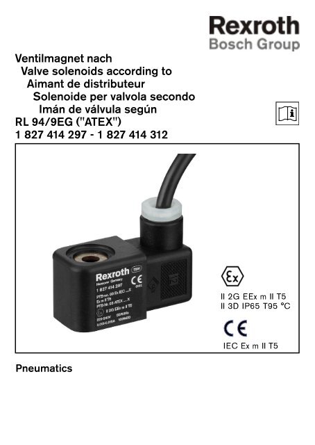
<strong>Ventilmagnet</strong> <strong>nach</strong><strong>Valve</strong> <strong>solenoids</strong> <strong>according</strong> <strong>to</strong>Aimant de distributeurSolenoide per valvola secondoImán de válvula segúnRL 94/9EG ("ATEX")1 827 414 297 - 1 827 414 312II 2G EEx m II T5II 3D IP65 T95 °CIEC Ex m II T5Pneumatics
2 Bosch Rexroth
Bosch RexrothInhaltsverzeichnisInhaltsverzeichnis31 Sicherheitshinweise ................................................................ 42 Installation..................................................................................... 62.1 Montage ..................................................................................... 62.2 Elektrische Anschluss ............................................................. 62.3 Inbetriebnahme ......................................................................... 73 Betrieb............................................................................................. 73.1 Medium ....................................................................................... 73.2 Betriebsdruck ........................................................................... 74 Störungen...................................................................................... 84.1 Vorgehensweise ....................................................................... 85 Technische Daten ...................................................................... 85.1 Temperaturklasse ..................................................................... 85.1 Elektrische Leistung ................................................................ 96 Ersatzteile ..................................................................................... 106.1 Bestellung .................................................................................. 107 Konformitätserklärung ........................................................... 10
4 SicherheitshinweiseBosch Rexroth1 Sicherheitshinweise☞Sehr geehrter Kunde!Beachten Sie die Sicherheitshinweise undmachen Sie sich mit dem Inhalt dieser Betriebsanleitungvertraut, bevor Sie mit der Installationbeginnen.Bei Nichtbeachtung dieser Hinweise sowiebei nicht sachgemäßen Eingriffen in dasGerät entfällt jegliche Haftung unsererPerson. Ferner erlischt die Garantie aufGeräte und Zubehörteile.Beachten Sie die Hinweise dieser Betriebsanleitungsowie die Einsatzbedingungen undzulässigen Daten, die aus den Aufdrucken /Typenschildern, der jeweiligen Geräte hervorgehen.Richten Sie sich bei der Auswahl und demBetrieb eines Gerätes <strong>nach</strong> den allgemeinenRegeln der Technik.Die Zulassung der PTB bezieht sich ausschließlichauf <strong>Ventilmagnet</strong>e mitBosch Rexroth Ankersystemen.
Bosch RexrothSicherheitshinweise5Achtung, es besteht Verbrennungsgefahr! DieOberfläche der Magnetspule kann bei Dauerbetriebsehr warm werden.Treffen Sie geeignete Maßnahmen, um unbeabsichtigtesAktivieren oder unzulässige Beeinträchtigungenauszuschließen.Beachten Sie, dass in unter Druck stehendenSystemen Leitungen und Ventile nicht gelöst werdendürfen.GültigkeitDiese Betriebsanleitung gilt für:– <strong>Ventilmagnet</strong><strong>nach</strong> RL 94/9/EG ("ATEX")mit den Teilenummern1 827 414 297 bis 1 827 414 312
6 InstallationBosch Rexroth2 Installation☞2.1 MontageAchten Sie <strong>nach</strong> dem Entfernen der Verpackungdarauf, dass in das System keine Verschmutzung gelangt.Beachten Sie vor der Montage des Systems darauf,dass keine Verschmutzung in den Rohrleitungen oderim Ventilgehäuse vorliegt.Achten Sie beim Einsetzen des Systems darauf, dassder O-Ring am Flansch nicht beschädigt wird.Beachten Sie bei Wand an WanMontage(Batteriemontage) den Mindestabstand für die jeweiligeTemperaturklassen(s. Technische Daten).- Beliebige Einbaulage zulässig, vorzugsweiseMagnetsystem oben.- Magnetspule um 90° versetzt arretierbar.- Anzugsdrehmoment der Befestigungsmutter:Metallmutter 0,8 +/-0,12 Nm,Kunsts<strong>to</strong>ffmutter 0,5 +/-0,075 NmKunsts<strong>to</strong>ffmutter geschlossen 1,2 +0,2 Nm2.2 Elektrischer AnschlußAnschlusskabel ist ausgelegt für Schraub-Klemmverbindungen.Achten Sie beim Verschrauben der Anschlusslitzendarauf, dass die Aderenden vollständig in derVerbindungsklemme sitzen.Verhindern Sie ein scharfes Abknicken derAnschlussleitungen und Litzen, um Kurzschlüsse undUnterbrechungen zu vermeiden.
Bosch RexrothBetrieb72.3 InbetriebnahmeVor Inbetriebnahme des Gerätes ist sicherzustellen,dass die Gesamtmaschine bzw. die Anlage den Bestimmungender EMV-Richtlinie entspricht.3 Betrieb3.1 MediumAls zulässige Medien kommen Gase und Flüssigkeitenin Betracht, die das System und die beinhaltendenDichtwerks<strong>to</strong>ffe nicht angreifen.Die maximal zulässige Medientemperatur beträgt80°C.Vermeiden Sie, das das Gerät von außen mit flüssigenoder korrodierenden Medien in Berührungkommt.3.2 BetriebsdruckDer Betriebsdruck des Gerätes richtet sich <strong>nach</strong> demjeweils verwendeten Anker-/Ventilsystem und beträgtmax. 12 bar.Belasten Sie das System nicht durch Biegung oderTorsion.
8 Störungen / Technische DatenBosch Rexroth4 Störungen4.1 Vorgehensweise5 Technische DatenÜberprüfen Sie bei Störungen die Leitungsanschlüsse,die Betriebsspannung und den Betriebsdruck.Sollte die Störung dadurch nicht behoben sein,dann stellen Sie sicher, dass am Gerät kein Druckansteht und trennen Sie das Gerät von derVersorgungsspannung und wenden Sie sich mit demdefekten Gerät an au<strong>to</strong>risiertes und geschultes Fachpersonal.5.1 Temperaturklasse T5Baubreite: 30 mmMaximal zulässige Medientemperatur 80°CBetriebsspannungs<strong>to</strong>leranz +/- 10%Betriebsdruck je <strong>nach</strong> Anker-/Ventilsystem,maximal 12 bar<strong>Ventilmagnet</strong> 1 827 414 297 - 1 827 414 312II 2G EEx m II T5 IEC Ex m II T5II 3D IP65 T95 °C5.2 Elektrische LeistungTypStromartTemperaturim Einzelbetrieb od.BatteriemontageBatteriemontage,Mindestabstand1 827 414 297 bis ... 3021 827 414 305 bis ... 310Wechselstrom 50 ... 60 Hz-20°C - +50°C-20°C - +50°Cja0 mm1 827 414 303 und ... 3041 827 414 311 und ... 312Gleichstrom, max. 20%Welligkeit-20°C - +50°C-20°C - +40°Cja0 mm
Bosch RexrothTechnische Daten9NennspannungU N[V]Nennstrom1)I N[mA]NennleistungP N[VA]GrenzleistungP G[VA]Sicherung[mA]Nennstrom1)I N[mA]NennleistungP N[W]GrenzleistungP G[W]Sicherung[mA]24 124 2,5 2,4 315 136 3,3 3,0 315110 27 3,0 2,8 80 - - - -220 13 2,8 2,6 32 - - - -240 15 3,6 3,4 40 - - - -1) (Bemessungsstrom)2) Max. Leistung bei Erwärmung bis an thermische Belastbarkeitsgrenze3) Jedem <strong>Ventilmagnet</strong>en muss als Kurzschlusssicherung eine seinemBemessungsstrom entsprechende Sicherung (max. 3-facher Bemessungsstrom<strong>nach</strong> DIN 41571 oder IEC 127) bzw. ein Mo<strong>to</strong>rschutzschalter mitKurzschluss- und thermischer Schnellauslösung (Einstellung auf Bemessungsstrom)vorgeschaltet werden. Diese Sicherung darf im zugehörigenVersorgungsgerät untergebracht sein oder muss separat vorgeschaltet werden.Die Sicherungs-Bemessungsspannung muss gleich oder größer als dieangegebene Nennspannung des Magneten sein. Das Ausschaltvermögen desSicherungssatzes muss gleich oder größer als der maximal anzunehmendeKurzschlussstrom am Einbauort sein.
10 Eratzteile/KonformitätserklärungBosch Rexroth6 Ersatzteile6.1 BestellungErsatzeile bestellen Sie komplett unter Angabe derIdent.-Nummer, welche auf den Geräten angebrachtist (Aufdruck, Typenschild).7 KonformitätserklärungIm Sinne der Richtlinie Explosionsschutz 94/9/EG.Hiermit bestätigen wir, dass die vorgenannten <strong>Ventilmagnet</strong>e der BoschRexroth AG den wesentlichen Anforderungen entsprechen, die in den Richtliniendes Rates zur Angleichung der Rechtsvorschriften der Mitgliedsstaatenfür Geräte und Schutzsysteme zur bestimmungsgemäßen Verwendung inexplosionsgefährdeten Bereichen (94/9/EG) in der aktuellen Fassung festgelegtist.Die Erklärung gilt für alle Exemplare, die <strong>nach</strong> den beim Hersteller hinterlegtenFertigunsunterlagen – die Bestandteil dieser Erkärung sind – hergestelltwurden.Die <strong>Ventilmagnet</strong>e sind elektrische Komponenten und dürfen nur durch Fachpersonalinstalliert werden; die einschlägigen Vorschriften sind zwingend zubeachten.<strong>Ventilmagnet</strong> 1 827 414 297 - 1 827 414 312II 2G EEx m II T5 IEC Ex m II T5 II 3D IP65 T95 °CFür den <strong>Ventilmagnet</strong> gilt die Baumusterprüfbescheinigung mit derNummer PTB 03 ATEX 2081 X und PTB-No. Ex - 03 IEC 2082 XDie Konformität mit der Bauart PTB-No. Ex - 03 ATEX N 033ausgestellt durch die PTB (Zulassungsstellen-Nummer 0102).Der <strong>Ventilmagnet</strong> ist ein vergussgekapseltes elektrisches Betriebsmittel derGruppe II für die Verwendung in Atmosphären der Kategorie 2G und 3Dausgelegt ist (Temperaturkalsse siehe Aufdruck). Das CE-gekennzeichneteGerät stimmt mit folgenden Normen überein: siehe nächste Seite
Bosch RexrothKonformitätserklärung11DIN EN 50 014DIN EN 50 028IEC 60079-18Elektrische Betriebsmittel für explosionsgefährdete Bereiche(Allgemeine Bestimmungen)Elektrische Betriebsmittel für explosionsgefährdete Bereiche(Vergusskapselung m)Elektrische Betriebsmittel für explosionsgefährdeteBereiche (Encapsulation m)DIN EN 50 281-1-1Elektrische Betriebsmittel zur Verwendung in Bereichenmit brennbarem Staub.DIN EN 60529DIN EN 61000-6-2DIN EN 61000-6-4DIN VDE 0580Schutzarten durch Gehäuse (IP-Grad)Fachgrundnorm Elektromagnetische Verträglichkeit,Störaussendung Industriebereich (wird erfüllt mit zusätzlichenschaltungstechnischen Maßnahmen)1)Fachgrundnorm Elektromagnetische Verträglichkeit,Störfestigkeit IndustriebereichAllgemeine Bestimmungen für elektromagn. GeräteRichtlinie 94/9/EGGeräte zur bestimmungsgemäßen Verwendung inexplosionsgefährdeten Bereichen.1) Anmerkung zur elektromagnetischen Verträglichkeit (Störaussendung):Für gleichstrombetriebene Geräte gibt es zur Zeit keine Vorschriften(Normen), die leitungsgebundene Störaussendungen definieren.Neuere Stromversorgungsgeräte unterdrücken die physikalisch bedingten Abschaltstörungender Magnetspule. Bei wechselstrombetriebenen Geräten istein Gleichrichter zwischen Spule und Kabel fest eingebaut. Hier treten keineunzulässigen Störaussendungen auf. Bei gleichstrombetriebenen Geräten isteine Abschirmung des Kabels erforderlich.Bosch Rexroth AGRobert Bosch Str. 2D-71701 SchwieberdingenSchwieberdingen,den 14.07.2003, gez. i.V. A. Gerhard, Entwicklungsleiter Pneumatik
12 Bosch Rexroth
Bosch RexrothTable of contententsTable of contents131 Safety instructions.................................................................... 42 Installation..................................................................................... 62.1 Assembly .................................................................................... 62.2 Electrical connection ............................................................... 62.3 Initial startup .............................................................................. 73 Operation ....................................................................................... 73.1 Medium ....................................................................................... 73.2 Operating pressure ................................................................. 74 Disruptions ................................................................................... 84.1 Procedure .................................................................................. 85 Technical data ............................................................................. 85.1 Temperature class .................................................................... 85.1 Electrical power ........................................................................ 96 Spare parts ................................................................................... 106.1 Ordering ..................................................................................... 107 Declaration of conformity ..................................................... 10
14 Safety instructionsBosch Rexroth1 Safety instructions☞Dear cus<strong>to</strong>mer,Please familiarize yourself thoroughly with thesafety and operating instructions before startingthe installation.We are exempt from liability if theseinstructions are not followed or ifunauthorized work on the device has beendone. Furthermore, the guarantee no longerapplies <strong>to</strong> devices and accessory parts.Please follow the instructions in this manual , aswell as the operating conditions andpermissible data listed on the imprint ornameplate on each device.Please comply with the common technicalregulations when selecting and operating oneof these devices.PTB approval only applies <strong>to</strong> <strong>solenoids</strong> with BoschRexroth armature systems.
Bosch RexrothSafety instructions15Warning, danger of fire! The surface of the valve<strong>solenoids</strong> can become very warm under constan<strong>to</strong>peration.Take suitable measures <strong>to</strong> prevent unmoni<strong>to</strong>redactivation or unpermitted impairment.Lines and valves may only be loosened in apressure-free system.ValidityThese operating instructions apply <strong>to</strong>:– <strong>Valve</strong> <strong>solenoids</strong><strong>according</strong> <strong>to</strong> RL 94/9/EC ("ATEX")with part numbers1 827 414 297 <strong>to</strong> 1 827 414 312
16 InstallationBosch Rexroth2 Installation2.1 AssemblyPlease take care when removing the packaging thatno contaminants end up in the system.Before assembling the system check that there is nocontamination in the pipings or the valve housing.Pay attention that the O ring on the flange is notdamaged when installing the system.Allow enough room for the mimimum distancecorresponding <strong>to</strong> the temperature classes wheninstalling the valve solenoid on a wall (batteryassembly) (see technical data).☞- All installation positions are permitted, but aposition with the magnet system at the <strong>to</strong>p ispreferable.- Solenoid coils can be offset and s<strong>to</strong>ppedat 90°.- Tightening <strong>to</strong>rque for the mounting nut:Metal nut 0.8 +/-0.12 NmPlastic nut 0.5 +/-0.075 NmClosed plastic nut 1.2 +0.2 Nm2.2 Electrical connectionConnection cable has been designed for screw/clamp connections.Please pay attention when screwing in theconnection strands that all of the wire ends arecompletely in the connection clamp.To avoid short circuits and disruptions, do not bendthe connection cable and strands.
Bosch RexrothOperation172.3 Initial startupPlease check that the entire machine or systemcorresponds <strong>to</strong> the regulations in the EMCguidelines before initial startup.3 Operation3.1 MediumGases and liquids that do not corrode the system orthe sealing materials contained within are permittedmedia.The maximum permissible media temperature is80°C.Please keep liquids or corrosive media away from theoutside of the device.3.2 Operating pressureThe device's operating pressure depends on thearmature/valve system used and may be a maximumof 12 bar.Do not add any stress <strong>to</strong> the system by bending or<strong>to</strong>rsion.
18 Disruptions/Technical dataBosch Rexroth4 Disruptions4.1 ProcedureCheck the cable connections, operating voltage, andthe operating pressure if there are any disruptions.If this does not solve the problem, check that thedevice is pressure-free, disconnect the device fromthe power supply, and contact an authorized andtrained specialist for repairs.5 Technical data5.1 Temperature class T5Width: 30 mmMaximum permissable media temperature 80°COperating voltage <strong>to</strong>lerance +/- 10%Operating pressure depending on armature/valvesystemMaximum 12 bar<strong>Valve</strong> <strong>solenoids</strong> 1 827 414 297 - 1 827 414 312II 2G EEx m II T5 IEC Ex m II T5II 3D IP65 T95 °C5.2 Electrical performanceTypeType of currentTemperature inindividual operationor battery assemblyBattery assembly,minimum distance1 827 414 297 <strong>to</strong> 3021 827 414 305 <strong>to</strong> 310Alternating current50 <strong>to</strong> 60 Hz-20°C - +50°C-20°C - +50°CYes0 mm1 827 414 303 and 3041 827 414 311 and 312Direct current,max. 20% ripple-20°C - +50°C-20°C - +40°CYes0 mm
Bosch RexrothTechnical data19Nom.voltageU N[V]Nom.curr. 1)I N[mA]RatedpowerP N[VA]Loadlimit 2)P G[VA]Fuse 3)[mA]Nom.curr. 1)I N[mA]RatedpowerP N[W]LoadlimitP G[W]Fuse 3)[mA]24 124 2.5 2.4 315 136 3.3 3.0 315110 27 3.0 2.8 80 - - - -220 13 2.8 2.6 32 - - - -240 15 3.6 3.4 40 - - - -1) (Reference current)2) Max. power when heated <strong>to</strong> the thermal load limit3) To prevent short circuits, every solenoid must have a fuse that corresponds<strong>to</strong> the particular reference current (max. 3x reference current <strong>according</strong> <strong>to</strong>DIN 41571 or IEC 127) or a mo<strong>to</strong>r protection switch which is activated whena short circuit occurs or when it is <strong>to</strong>o hot (set <strong>to</strong> the reference current)connected in a series. This fuse may be located in the power supply unit ormust be connected separately in a series. The fuse reference current must beequal <strong>to</strong> or greater than the listed nominal voltage for the <strong>solenoids</strong>. The cu<strong>to</strong>ffcapacity of the set of fuses must be equal <strong>to</strong> or greater than the maximumexpected short circuit current at the installation site.
20 Spare parts/Declaration of conformityBosch Rexroth6 Spare parts6.1 OrderingYou can order spare parts using the ID numberlocated on the device (imprint, nameplate).7 Declaration of conformityIn accordance with the explosion protection guideline 94/9/EC.We hereby confirm that the above mentioned valve <strong>solenoids</strong> from BoschRexroth AG conform with the requirements set out by the European Council inthe guidelines <strong>to</strong> harmonize the legal provisions of the member states forequipment and protection systems for use in areas subject <strong>to</strong> explosions (94/9/EC) as set out in the current version.This declaration applies <strong>to</strong> all models that are manufactured <strong>according</strong> <strong>to</strong> theproduction documentation that is a part of this declaration.The <strong>solenoids</strong> are electric components and may only be installed by trainedpersonnel; the relevant regulations must be observed.<strong>Valve</strong> solenoid 1 827 414 297 - 1 827 414 312II 2G EEx m II T5 IEC Ex m II T5 II 3D IP65 T95°CThe pro<strong>to</strong>type test approval numbers PTB 03 ATEX 2081 X and PTB no.Ex-03 IEC 2082 X are applicable <strong>to</strong> the <strong>solenoids</strong>.The conformity <strong>to</strong> PTB no. Ex - 03 ATEX N 033 has been issued by the PTB(Physikalisch-Technische Bundesanstalt) (registration office number 0102).The valve solenoid is a group II encapsulated electrical device that is suitablefor use in 2G and 3D atmospheres (see the imprint for the temperature class).The CE marked device fulfils the following standards: see next page.
Bosch RexrothDeclaration of conformity21DIN EN 50 014DIN EN 50 028IEC 60079-18Electrical apparatus for potentially explosive atmospheres(general requirements)Electrical apparatus for potentially explosive atmospheres(encapsulation m)Electrical apparatus for potentially explosive atmospheres(encapsulation m)DIN EN 50 281-1-1Electrical apparatus for use in the presence ofcombustible dustDIN EN 60529DIN EN 61000-6-2DIN EN 61000-6-4DIN VDE 058094/9/EC guidelineDegrees of protection provided by enclosures (IP code)Electromagnetic compatibility (EMC), generic standards;interference for industrial environments (supplementedwith additional technical measures for circuits)1)Electromagnetic compatibility (EMC), generic standards,immunity for industrial environmentsGeneral specifications for electromagnetic devices andcomponentsEquipment and protection systems for use in areassubject <strong>to</strong> explosions1) A note on electromagnetic compatibility (interference):There are currently no regulations that define cable-related interference fordevices that are operated with direct current. Modern power supply unitssuppress the physical cu<strong>to</strong>ff disruption of the solenoid coil. A rectifier isinstalled between the coil and cable in devices that operate with alternatingcurrent. There is no interference here. The cable for direct current devicesmust have a protective coating.Bosch Rexroth AGRobert Bosch Str. 271701 Schwieberdingen, GermanySchwieberdingen, GermanyJuly 14, 2003, p.p. A. Gerhard, Pneumatics Development Manager
22 Bosch Rexroth
Bosch RexrothTable des matièresTable des matières231 Instructions de sécurité ......................................................... 42 Installation..................................................................................... 62.1 Montage ..................................................................................... 62.2 Raccordement électrique ...................................................... 62.3 Mise en service ........................................................................ 73 Fonctionnement ......................................................................... 73.1 Médium ....................................................................................... 73.2 Pression de service ................................................................. 74 Perturbations ............................................................................... 84.1 Procédures ................................................................................ 85 Données techniques ................................................................ 85.1 Classe de température ........................................................... 85.1 Puissance électrique ............................................................... 96 Pièces de rechange .................................................................. 106.1 Commande ................................................................................ 107 Déclaration de conformité .................................................... 10
24 Instructions de sécuritéBosch Rexroth1 Instructions de sécurité☞Cher client,Veuillez respecter les instructions de sécurité etprendre connaissance du contenu de cemanuel d'utilisation avant de commencerl'installation.Le non respect de ces instructions ou uneintervention inappropriée dans l'appareilannule <strong>to</strong>ute responsabilité de notre part.Ceci annule la garantie sur l'appareil et lesaccessoires.Veuillez respecter les instructions de ce manueld’utilsation ainsi que les conditions d’emploi etles données au<strong>to</strong>risées qui sont reportées surles étiquettes / les plaques signalétiques desappareils correspondants.Reportez vous aux règles générales detechnique lors du choix et de l'utilisation d'unappareil.L'au<strong>to</strong>risation de la PTB se rapporte exclusivementaux aimants de distributeur avec les systèmes àtirant de Bosch Rexroth.
Bosch RexrothInstructions de sécurité25Attention, il existe un risque de brûlure ! La surfacede la bobine électromagnétique peut devenirtrès chaude lors d'une sollicitation continue.Prenez les mesures adéquates afin de pouvoirexclure une activation involontaire ou des dégradationsinadmissibles.Veuillez observer que, dans des systèmes souspression, les câbles et les distributeurs ne doiventpas être démontés.Validité Ce manuel d'utilisation est valable pour :– aimant de distributeurselon RL 94/9/EG ("ATEX")avec les numéros de pièces1 827 414 297 à 1 827 414 312
26 InstallationBosch Rexroth2 Installation☞2.1 MontageLorsque vous enlevez l'emballage, veuillez faire attentionqu'aucune salissure n'entre dans le système.Avant d'effectuer le montage du système, veuillezfaire attention qu'aucune salissure ne soit présentedans la tuyauterie ou dans le boîtier du distributeur.Lors de la mise en service du système, veuillez faireattention de ne pas endommager le joint <strong>to</strong>rique de labride.Lors d'un montage en batterie, veuillez respecterl'écart minimal prévu par la classe de températurecorrespondante (voir données techniques).- Position de montage désirée au<strong>to</strong>risée, le systèmeélectro-aimant de préférence en haut.- Bobine électromagnétique blocable, orientée à90°.- Couple de serrage de l'écrou de fixation :Ecrou en métal 0,8 +/-0,12 Nm,Ecrou en plastique 0,5 +/-0,075 NmEcrou en plastique fermé 1,2 +0,2 Nm2.2 Raccordement électriqueLe câble de raccordement est conçu pour le raccordementpince / vis.Lors du vissage des fils de raccordement, veuillezfaire attention à ce que les extrémités des conducteurssoient complètement placées dans la pince deraccordement.Evitez le pliage prononcé des câbles de raccordementet des conducteurs, afin d'empêcher les courtscircuitset les interruptions.
Bosch RexrothFonctionnement272.3 Mise en serviceAvant la mise en service de l'appareil, il faut s'assurerque l'ensemble de la machine, respectivement l'installation,répond au règlement de la directive CEM.3 Fonctionnement3.1 FluideLes fluides au<strong>to</strong>risés sont les gaz et les liquides quin'attaquent pas le système et les matériaux étanchesqu'il comporte.La température maximale au<strong>to</strong>risées des fluides estde 80 °C.Evitez le contact extérieur de l'appareil avec des liquidesou des moyens corrosifs.3.2 Pression de serviceLa pression de service de l'appareil dépend du systèmede tirant / distributeur correspondant utilisé ets'élève à max. 12 bar.Ne surchargez pas le système par une flexion ou une<strong>to</strong>rsion.
28 Perturbations / Données techniquesBosch Rexroth4 Perturbations4.1 ProcéduresLors de perturbations, vérifiez les raccordements decâbles, la tension et la pression de service.Si le dysfonctionnement n'est pas réparé par cetteaction, assurez-vous alors que l'appareil n'est passous tension et débranchez-•le. Veuillez vous adresserau personnel compétent et au<strong>to</strong>risé avec l'appareildéfectueux.5 Données techniques5.1 Classe de température T5Largeur : 30 mmTempérature du fluide maximale au<strong>to</strong>risée 80 °CTolérance de la tension de service +/- 10 %Tension de service selon système de tirant /distributeur, maximal 12 barAimant de distributeur 1 827 414 297 - 1 827 414 312II 2G EEx m II T5 IEC Ex m II T5II 3D IP65 T95 °C5.2 Puissance électriqueModèleCourantTempérature enfonctionnementsimple ou montageen batterieMontage en batterie,écart minimal1 827 414 297 à ... 3021 827 414 305 à ... 310Alternatif 50 à 60 Hz-20 °C à +50 °C-20 °C à +50 °COui0 mm1 827 414 303 et ... 3041 827 414 311 et ... 312Continu, ondulation max.20 %-20 °C à +50 °C-20 °C à +40 °COui0 mm
Bosch RexrothDonnées techniques29Tens.nom.Cour.nom. 1)Puiss.nom.Puiss.limite 2)Fusible3)Cour.nom. 1)Puiss.nom.Puiss.limiteFusible3)U N[V] I N[mA] P N[VA] P G[VA] [mA] I N[mA] P N[W] P G[W] [mA]24 124 2,5 2,4 315 136 3,3 3,0 315110 27 3,0 2,8 80 - - - -220 13 2,8 2,6 32 - - - -240 15 3,6 3,4 40 - - - -1) (Courant de calcul)2) Puissance max. lors de l'échauffement jusqu'à la limite de charge thermiqueadmissible3) Comme protection contre les courts-circuits, chaque aimant de distributeurdoit être commuté en série à un fusible correspondant au courant de calcul(max. courant de calcul triple selon DIN 41571 ou IEC 127) ou un disjoncteurà déclenchement rapide thermique ou aux courts-circuits (paramétrage seloncourant de calcul). Ce fusible peut être inséré dans l'appareil d'alimentationcorrespondant ou doit être connecté séparément. La tension de calcul dufusible doit être égale ou supérieure à la tension nominale indiquée del'aimant. La capacité d'interruption du jeu de fusible doit être égale ou supérieureau courant de courts-circuits maximal assumé au lieu d'installation.
30 Pièces de rechange/Déclaration de conformité Bosch Rexroth6 Pièce de rechange6.1 CommandeVous pouvez commander <strong>to</strong>utes les pièces derechange en donnant le numéro d'identification, setrouvant indiquer sur les appareils (étiquette, plaquesignalétique).7 Déclaration de conformitéSelon la directive Protection contre les explosions 94/9/CE.Nous confirmons ainsi que les aimants de distributeur de Bosch Rexroth AGcités précédemment répondent aux exigences essentielles stipulées dans laversion actuelle de la directive du taux d'harmonisation des consignes de droitdes états membres pour les appareils et les systèmes de protection à usageconforme dans les milieux à risque d'explosion (94/9/CE).La déclaration est valable pour <strong>to</strong>us les exemplaires fabriqués selon les documentationstechniques déposés par le fabricant - qui font parties de cettedéclaration.Les aimants de distributeur sont des composants électriques et doivent êtreinstallés seulement par le personnel compétent ; il est impératif de respecterles consignes correspondantes.Aimant de distributeur 1 827 414 297 - 1 827 414 312II 2G EEx m II T5 IEC Ex m II T5 II 3D IP65 T95 °CLe Certificat de contrôle des échantillons de montage numéroPTB 03 ATEX 2081 X et PTB-No. Ex - 03 IEC 2082 X, est valablepour les aimants de distributeur.La Conformité à la construction PTB-No. Ex - 03 ATEX N 033est établie par la PTB (numéro d'au<strong>to</strong>risation 0102).L'aimant de distributeur est un appareil électrique enrobé du groupe II conçupour l'utilisation en atmosphères de catégories 2G et 3D (classe de température,voir étiquette). L'appareil marqué CE répond aux normes cités ci-après.
Bosch RexrothDéclaration de conformité31DIN EN 50 014DIN EN 50 028IEC 60079-18Appareils électriques pour les domaines à risques d'explosion(dispositions générales)Appareils électriques pour les domaines à risques d'explosion(enrobage m)Appareils électriques pour les domaines à risques d'explosion(encapsulation m)DIN EN 50 281-1-1Appareils électriques pour l'utilisation dans les domainesavec poussières combustiblesDIN EN 60529Type de protection selon boîtier (degré IP)DIN EN 61000-6-2DIN EN 61000-6-4DIN VDE 0580Directive 94/9/CENorme de base pour la compatibilité électromagnétiqueet l'émission d'impulsions parasites dans le domaine industriel(cette norme est respectée grâce à des mesuresde technique de commutation supplémentaires)1)Norme de base pour la compatibilité électromagnétiqueet la résistance aux interférences dans le domaine industrielRèglements généraux pour les appareils électromag.Appareils conformes pour utilisation dans les domaines àrisques d'explosion1) Remarque à propos de la compatibilité électromagnétique (émissiond'impulsions parasites) :Pour les appareils fonctionnant sous courant continu, il n'existe à l'heureactuelle pas de directive (norme), définissant l'émission d'impulsions parasitesliée à la transmission.Les nouveaux appareils d'approvisionnement en courant suppriment lesperturbations de coupure de cause physique de la bobine électromagnétique.Pour les appareils fonctionnant sous courant alternatif, un redresseur a étéintégré entre la bobine et le câble. Des émissions d'impulsions parasites nonconformes sont ainsi exclues. Pour les appareils fonctionnant sous courantcontinu, il est nécessaire d'isoler les câbles.Bosch Rexroth AGRobert Bosch Str. 2D-71701 SchwieberdingenSchwieberdingen,le 14.07.2003, par A. Gerhard, Chef du développement Pneumatics
32 Bosch Rexroth
Bosch RexrothSommarioSommario331 Indicazioni di sicurezza .......................................................... 42 Installazione ................................................................................. 62.1 Montaggio .................................................................................. 62.2 Connessione elettrica ............................................................. 62.3 Messa in funzione .................................................................... 73 Funzionamen<strong>to</strong> ........................................................................... 73.1 Mezzo .......................................................................................... 73.2 Pressione di esercizio ............................................................. 74 Guasti .............................................................................................. 84.1 Procedura .................................................................................. 85 Dati tecnici .................................................................................... 85.1 Classe di temperatura ............................................................ 85.1 Prestazione elettrica ................................................................ 96 Parti di ricambio ......................................................................... 106.1 Ordinazione ............................................................................... 107 Dichiarazione di conformità ................................................. 10
34 Indicazioni di sicurezzaBosch Rexroth1 Indicazioni di sicurezza☞Gentile cliente!La preghiamo di prestare attenzione alleindicazioni di sicurezza e di leggereattentamente le istruzioni per l’uso prima diiniziare l’installazione.Se le suddette indicazioni non vengonoosservate e vengono eseguiti interventi nonadeguati nello strumen<strong>to</strong>, la nostra Ditta nonsi assume alcuna responsabilità. La garanziasugli strumenti e gli accessori verrà inoltreinvalidata.Osservare le istruzioni per l'uso nonché lecondizioni d'impiego ed i dati consentiti,riportati nelle diciture e nelle targhette deirispettivi strumenti.Nella scelta e nel funzionamen<strong>to</strong> di unostrumen<strong>to</strong> orientarsi alle regole generali dellatecnica.L'omologazione PTB si riferisce esclusivamente asolenoidi per valvola con sistemi di tiranti BoschRexroth.
Bosch RexrothIndicazioni di sicurezza35Attenzione, pericolo di combustione! La superficiedella bobina magnetica può diventare mol<strong>to</strong> caldain servizio continuo.Prendere le misure necessarie per evitareun'attivazione involontaria o danni illeciti.Osservare che nei sistemi sot<strong>to</strong> pressione i cavi ele valvole non devono essere allentati.ValiditàQueste istruzioni per l'uso sono valide per:– Solenoidi per valvolasecondo RL 94/9/EG ("ATEX")con codice d'ordinazioneda 1 827 414 297 a 1 827 414 312
36 InstallazioneBosch Rexroth2 Installazione2.1 MontaggioDopo avere rimosso l'imballaggio fare attenzione chenel sistema non entri dello sporco.Prima di montare il sistema controllare che non vi siasporco nelle tubazioni o nel corpo delle valvole.Controllare, prima di utilizzare il sistema, che l'anellodi tenuta nella flangia non sia danneggia<strong>to</strong>.Per il montaggio da parete a parete (montaggio inbatteria) osservare la distanza minima per le rispettiveclassi di temperature (v. Dati tecnici).☞- Posizione di montaggio a scelta consentita,preferibilmente con sistema di magneti versol'al<strong>to</strong>.- Bobina magnetica arrestabile, sfalsabile di 90°.- Coppia di serraggio del dado di fissaggio:dado di metallo 0,8 +/-0,12 Nm,dado di plastica 0,5 +/-0,075 Nmdado di plastica chiuso 1,2 +0,2 Nm2.2 Connessione elettricaIl cavo di collegamen<strong>to</strong> è posa<strong>to</strong> per collegamenticon morset<strong>to</strong> a vite.Avvitare i collegamenti flessibili facendo attenzioneche le estremità dei condut<strong>to</strong>ri siano perfettamente insede nel morset<strong>to</strong> a vite.Evitare una piegatura troppo forte dei cavi dicollegamen<strong>to</strong> e dei cavetti per evitare cor<strong>to</strong>circuiti einterruzioni.
Bosch Rexroth2.3 Messa in funzioneFunzionamen<strong>to</strong>37Prima della messa in funzione dell'apparecchioassicurarsi che l'intera macchina o l'impian<strong>to</strong>soddisfino le disposizioni delle norme CEM.3 Funzionamen<strong>to</strong>3.1 MezzoI mezzi consentiti sono gas e fluidi che non sonoaggressivi per il sistema e per i materiali perguarnizioni ivi contenuti.La temperatura massima del mezzo consentitaammonta a 80°C.Evitare che l'apparecchio venga a contat<strong>to</strong> con mezzifluidi o corrosivi.3.2 Pressione di esercizioLa pressione di esercizio dell'apparecchio dipendedal sistema di tiranti o di valvole usa<strong>to</strong> di volta in voltaed ammonta a max. 12 bar.Non caricare il sistema tramite piegatura o <strong>to</strong>rsione.
38 Guasti/ Dati tecniciBosch Rexroth4 Guasti4.1 ProceduraIn caso di guasti controllare i raccordi dei cavi, latensione e la pressione di esercizio.Se, nonostante i controlli, non è possibile ripararare ilguas<strong>to</strong>, assicurarsi che nell'apparecchio non si formipressione, separare l'apparecchio dalla tensione dialimentazione e rivolgersi a personale au<strong>to</strong>rizza<strong>to</strong> ecompetente con l'apparecchio difet<strong>to</strong>so.5 Dati tecnici5.1 Classe di temperatura T5Larghezza: 30 mmTemperatura del mezzo massima consentita 80°CTolleranza della tensione di esercizio +/- 10%Pressione di esercizio secondo il sistema di tiranti/divalvole, massimo 12 barSolenoide per valvola 1 827 414 297 - 1 827 414312II 2G EEx m II T5 IEC Ex m II T5II 3D IP65 T95 °C5.2 Prestazione elettricaTipoTipo correnteTemperaturaa servizio singolo omontagg. in batteriaMontaggio inbatteria,distanza minimada 1 827 414 297 a ... 302da 1 827 414 305 a ... 310Corrente alternata50 ... 60 Hz-20°C - +50°C-20°C - +50°Csì0 mmda 1 827 414 303 a ... 304da 1 827 414 311 a ... 312Corrente continua, max.20% ondulazione-20°C - +50°C-20°C - +40°Csì0 mm
Bosch RexrothDati tecnici39Tens.nom.U N[V]Corr.nom. 1)I N[mA]Prest.nom.P N[VA]Prest. Fusib. 3)lim. 2P G[VA] [mA]Corr.nom. 1)I N[mA]Prest.nom.P N[W]Prest.lim.P G[W]Fusib. 3)[mA]24 124 2,5 2,4 315 136 3,3 3,0 315110 27 3,0 2,8 80 - - - -220 13 2,8 2,6 32 - ---240 15 3,6 3,4 40 - - - -1) (Corrente di misurazione)2) Prestazione max. in riscaldamen<strong>to</strong> fino al limite di carico termico3) Per proteggere le elettrovalvole da cor<strong>to</strong>circui<strong>to</strong>, ogni solenoide per valvoladeve essere collega<strong>to</strong> in serie ad uno dei suoi fusibili corrispondente allacorrente di misurazione (max. 3 volte la corrente di misurazione secondoDIN 41571 o IEC 127) oppure ad un salvamo<strong>to</strong>re con sgancio rapido in casodi surriscaldamen<strong>to</strong> o cor<strong>to</strong>circui<strong>to</strong> (impostazione alla corrente dimisurazione). Il fusibile può essere alloggia<strong>to</strong> nel rispettivo apparecchio dialimentazione oppure deve essere collega<strong>to</strong> separatamente. La tensione dialimentazione del fusibile deve essere pari o superiore alla tensione nominaledel magnete indicata. La capacità di interruzione deve essere pari o superiorealla corrente di circui<strong>to</strong> max. da assorbire nel luogo di montaggio.
40 Parti di ricambio/Dichiarazione di conformitàBosch Rexroth6 Parti di ricambio6.1 OrdinazioneLe parti di ricambio possono essere ordinatecompletamente indicando il codice d'identificazioneappos<strong>to</strong> su ogni strumen<strong>to</strong> (digitura, targhetta).7 Dichiarazione di conformitàAi sensi della direttiva sulla protezione dalle esplosioni 94/9/CE.Con la presente confermiamo che i solenoidi summenzionati di Bosch RexrothAG rispondono a tutti i requisiti essenziali fissati dalle direttive del Consiglionell'attuale costituzione a proposi<strong>to</strong> dell'equiparazione delle norme giuridichedegli Stati Membri per un utilizzo a norma di apparecchi e sistemi diprotezione in set<strong>to</strong>ri a pericolo di esplosione (94/9/CE).La dichiarazione è valida per tutti gli esemplari che sono stati prodottisecondo la documentazione di produzione depositata dal fabbricante – che èparte di questa dichiarazione.I solenoidi per valvola sono componenti elettrici e devono essere installatesolo da personale specializza<strong>to</strong>; le disposizioni competenti devono essereosservate alla lettera.Solenoidi per valvola 1 827 414 297 - 1 827 414 312II 2G EEx m II T5 IEC Ex m II T5 II 3D IP65 T95 °CPer il solenoide il certifica<strong>to</strong> di collaudo modello con ilnumero PTB 03 ATEX 2081 X e PTB Ex - 03 IEC 2082 XLa Conformità con il tipo di costruzione PTB Ex - 03 ATEX N 033rilasciata da PTB (numero del luogo di omologazione 0102).Il solenoide per valvola è un mezzo di esercizio elettrico incapsula<strong>to</strong> delgruppo II pensa<strong>to</strong> per l'utilizzo in atmosfere delle categorie 2G e 3D (per laclasse di temperatura vedere dicitura). L'apparecchio con marchio CErisponde alle norme riportate alla pagina seguente.
Bosch RexrothDIN EN 50 014DIN EN 50 028IEC 60079-18Dichiarazione di conformitàMezzi di esercizio elettrici per set<strong>to</strong>ri a pericolo diesplosione (norme generali)Mezzi di esercizio elettrici per set<strong>to</strong>ri a pericolo diesplosione (incapsulazione 'm')Mezzi di esercizio elettrici per set<strong>to</strong>ri a pericolo diesplosione (incapsulazione 'm')41DIN EN 50 281-1-1Mezzi di esercizio elettrici per l'utilizzo in set<strong>to</strong>ri conpolvere combustibile.DIN EN 60529DIN EN 61000-6-2DIN EN 61000-6-4DIN VDE 0580Direttiva 94/9/CETipi di protezione garantiti dai corpi (grado IP)Norma base per la compatibilità elettromagnetica el'emissione di disturbo del set<strong>to</strong>re industriale (vienesoddisfatta con misure tecniche di circui<strong>to</strong> aggiuntive) 1)Norma base per la compatibilità elettromagnetica e laresistenza al disturbo nel set<strong>to</strong>re industrialeNorme generali per gli apparecchi elettromagneticiApparecchi per l'utilizzo a norma in set<strong>to</strong>ri a pericolo diesplosione.1) Annotazione sulla compatibilità elettromagnetica (emissione di disturbo):Per apparecchi azionati a corrente continua non vi sono al momen<strong>to</strong>disposizioni (norme) che definiscono le emissioni di disturbo legate ai cavi.Gli apparecchi ad alimentazione di corrente più recenti sopprimono i disturbidi interruzione di natura fisica della bobina magnetica. Per apparecchi azionatia corrente alternata è installa<strong>to</strong> permanentemente un raddrizza<strong>to</strong>re tra labobina ed il cavo. In ques<strong>to</strong> modo non penetrano emissioni di disturbo. Per gliapparecchi azionati a corrente continua è necessaria una schermatura delcavo.Bosch Rexroth AGRobert Bosch Str. 2D-71701 SchwieberdingenSchwieberdingen,14.07.2003, per A. Gerhard, diret<strong>to</strong>re dell'area di sviluppo del set<strong>to</strong>rePneumatica
42 Bosch Rexroth
Bosch RexrothÍndiceÍndice431 Instrucciones de seguridad ................................................. 42 Instalación ..................................................................................... 62.1 Montaje ....................................................................................... 62.2 Conexión eléctrica ................................................................... 62.3 Puesta en servicio ................................................................... 73 Servicio ........................................................................................... 73.1 Medio .......................................................................................... 73.2 Presión de servicio .................................................................. 74 Fallos de funcionamien<strong>to</strong> ...................................................... 84.1 Procedimien<strong>to</strong> ........................................................................... 85 Da<strong>to</strong>s técnicos ............................................................................ 85.1 Clase de temperatura ............................................................. 85.1 Potencia eléctrica .................................................................... 96 Repues<strong>to</strong>s ..................................................................................... 106.1 Pedidos ...................................................................................... 107 Declaración de conformidad ............................................... 10
44 Instrucciones de seguridadBosch Rexroth1 Instrucciones de seguridad☞Estimado cliente:Es indispensable respetar las instrucciones deseguridad y familiarizarse con el contenido deestas instrucciones de servicio antes deproceder con la instalación.En el caso de que no se sigan estasinstrucciones o se lleven a cabotransgresiones inadecuadas en el apara<strong>to</strong>,queda anulada <strong>to</strong>da responsabilidad pornuestra parte. Asimismo, en es<strong>to</strong>s casos seanula la garantía del apara<strong>to</strong> y susaccesorios.Respete las instrucciones de este manual, asícomo las condiciones de uso y los da<strong>to</strong>scorrespondientes indicados en las impresionesy placas de características de los distin<strong>to</strong>sequipos.En la selección y el funcionamien<strong>to</strong> de unequipo, guíese por las reglas generales de latécnica.La admisión de PTB se aplica exclusivamente a losimanes de válvula con sistemas de tirantes BoschRexroth.
Bosch RexrothInstrucciones de seguridad45¡Atención, riesgo de quemaduras! La superficiedel imán de válvula puede llegar a estar muycaliente en servicio continuo.Tome las medidas oportunas para evitar que seproduzcan ac<strong>to</strong>s o daños inadmisibles.Preste atención a no soltar los conduc<strong>to</strong>s yválvulas en los sistemas que se encuentren bajopresión.Validez Esta instrucción de servicio corresponde a:– Imán de válvulasegún RL 94/9/CE ("ATEX")con los números de referencia1 827 414 297 hasta 1 827 414 312
46 InstalaciónBosch Rexroth2 Instalación☞2.1 MontajeDespués del desembalaje, asegúrese de que no seintroduzca suciedad en el sistema.Antes del montaje del sistema, compruebe que nohaya suciedad en los conduc<strong>to</strong>s de los tubos ni en lacarcasa de la válvula.Durante la aplicación del sistema, asegúrese de queel anillo <strong>to</strong>roidal de la brida no se dañe.En el caso de montaje en la pared (montaje porbatería), compruebe la distancia mínima para lasdistintas clases de temperatura (consulte Da<strong>to</strong>stécnicos).- Posición de montaje cualquiera, siendopreferente ubicar el sistema magnético arriba.- Bobina magnética bloqueable a escalones de90°.- Par de apriete de la tuerca de fijación:Tuerca metálica 0,8 +/-0,12 Nm,Tuerca de plástico 0,5 +/-0,075 Nm,Tuerca de plástico cerrada 1,2 +0,2 Nm2.2 Conexión eléctricaEl cable de conexión está diseñado para uniones deapriete roscadas.Durante la fijación de los flexibles de conexión,asegúrese de que las extremidades de los cablesestén completamente introducidos en el borne defijación.Evite que se retuerzan las líneas de alimentacióny los hilos múltiples, con el fin de prevenircor<strong>to</strong>circui<strong>to</strong>s y discontinuidades.
Bosch Rexroth2.3 Puesta en servicioFuncionamien<strong>to</strong>47Antes de poner en servicio el equipo es necesarioasegurarse de que <strong>to</strong>das las máquinas y lainstalación cumplan los requisi<strong>to</strong>s de las directivasCEM.3 Servicio3.1 MedioComo medios permitidos se encuentran los gases yfluidos que no corroan el sistema ni los materialesobturadores contenidos.La temperatura máxima del medio permitida esde 80 °C.Evite que el equipo entre en contac<strong>to</strong> desde afueracon medios líquidos o corrosivos.3.2 Presión de servicioLa presión de servicio del equipo viene determinadapor el sistema de tirantes/ de válvulas utilizado yasciende a un máximo de 12 bares.No cargue el sistema mediante flexión o <strong>to</strong>rsión.
48 Fallos de funcionamien<strong>to</strong> / Da<strong>to</strong>s técnicosBosch Rexroth4 Fallos de funcionamien<strong>to</strong>4.1 Procedimien<strong>to</strong>En caso de averías, compruebe las conexiones delos cables, la tensión de servicio y la presión deservicio.En el caso de que no se solucione el problema,asegúrese de que no haya presión en el equipo,sepárelo de la tensión de alimentación y diríjase conel equipo defectuoso a personal especializado yau<strong>to</strong>rizado.5 Da<strong>to</strong>s técnicos5.1 Clase de temperatura T5Anchura: 30 mmTemperatura máxima del medio permitida 80 °CTolerancia de la tensión de servicio +/- 10%Presión de servicio por sistema de tirantes/ deválvulas, máximo 12 baresImán de válvula 1 827 414 297 - 1 827 414 312II 2G EEx m II T5 IEC Ex m II T5II 3D IP65 T95 °C5.2 Potencia eléctricaTipoClase de corrienteTemperaturaen servicioindividual omontaje por bateríaMontaje por batería,Distancia mínima1 827 414 297 hasta... 3021 827 414 305 hasta... 310Corriente alterna50 ... 60 Hz-20 °C - +50 °C-20 °C - +50 °Csí0 mm1 827 414 303 y ... 3041 827 414 311 y ... 312Corriente continua,máx. 20 % de ondulación-20 °C - +50 °C-20 °C - +40 °Csí0 mm
Bosch RexrothDa<strong>to</strong>s técnicos49Tens.nom.Corr.nom. 1)Poten.nom.Poten.límite 2)Fusible3)Corr.nom. 1)Poten.nom.Poten.límiteFusible3)U N[V] I N[mA] P N[VA] P G[VA] [mA] I N[mA] P N[W] P G[W] [mA]24 124 2,5 2,4 315 136 3,3 3,0 315110 27 3,0 2,8 80 - - - -220 13 2,8 2,6 32 - - - -240 15 3,6 3,4 40 - - - -1) (Corriente asignada)2) Potencia máxima en un calentamien<strong>to</strong> hasta el límite de carga térmico3) Todos los imanes de válvula deben tener conectados como seguro frente acor<strong>to</strong>circui<strong>to</strong>s un fusible correspondiente a su corriente asignada (máx. 3veces la corriente asignada según DIN 41571 ó IEC 127) o un interrup<strong>to</strong>r deprotección del mo<strong>to</strong>r con desconexión rápida térmica y de cor<strong>to</strong>circui<strong>to</strong>s(regulación según la corriente asignada). Este fusible se puede instalar en elequipo de alimentación asociado o debe conectarse por separado. La tensiónde referencia del fusible debe ser igual o superior a la tensión nominalindicada del imán. La capacidad de desconexión del juego del fusible debeser igual o superior a la corriente previsible del cor<strong>to</strong>circui<strong>to</strong> del lugar demontaje.
50 Repues<strong>to</strong>s/Declaración de conformidadBosch Rexroth6 Repues<strong>to</strong>s6.1 PedidosLos pedidos de los repues<strong>to</strong>s se realizan indicandoel número de identificación del componente, situadosobre el equipo (impresión, placa).7 Declaración de conformidadConforme la Directiva sobre riesgos de explosión 94/9/CE.Con la presente confirmamos que los mencionados imanes de válvula deBosch Rexroth AG cumplen los requisi<strong>to</strong>s correspondientes incluidos en laactual edición de las normativas europeas del Consejo para la regulación delas disposiciones legales de los estados miembros con respec<strong>to</strong> a losequipos y sistemas de protección para uso en atmósferas potencialmenteexplosivas (94/9/CE).La declaración es válida para <strong>to</strong>dos los ejemplares realizados según ladocumentación de fabricación (que es parte componente de estadeclaración) del fabricante.Los imanes de válvula son componentes eléctricos y sólo deben serinstaladas por personal técnico cualificado. El cumplimien<strong>to</strong> de loscorrespondientes requisi<strong>to</strong>s es de caracter obliga<strong>to</strong>rio.Imán de válvula 1 827 414 297 - 1 827 414 312II 2G EEx m II T5 IEC Ex m II T5 II 3D IP65 T95 °CPara el imán de válvula se aplica el Certificado de ensayo de modelo deconstrucción con númeroPTB 03 ATEX 2081 X y PTB-No. Ex - 03 IEC 2082 XLa Conformidad con el modelo de construcciónPTB-No. Ex - 03 ATEX N 033 se expone mediante la PTB (número de lugarde homologación 0102).
Bosch RexrothDeclaración de conformidad51DIN EN 50 014DIN EN 50 028IEC 60079-18DIN EN 50 281-1-1DIN EN 60529DIN EN 61000-6-2DIN EN 61000-6-4DIN VDE 0580Directiva 94/9/CEEquipo eléctrico para zonas con riesgos de explosión(normas generales)Equipo eléctrico para zonas con riesgos de explosión (mencapsulado)Equipo eléctrico para zonas con riesgos de explosión (mencapsulado)Equipo eléctrico para uso en zonas con polvo inflamable.Tipos de protección mediante carcasa (grado IP)Norma básica para la CEM, emisión perturbadora desec<strong>to</strong>res industriales (se completará con medidastécnicas de circui<strong>to</strong>s adicionales)1)Norma básica para la CEM, resistencia a interferenciasde sec<strong>to</strong>res industrialesNormas generales para equipos electromagnéticosEquipos para uso en atmósferas potencialmenteexplosivas.1) Nota sobre la CEM (emisión perturbadora): En el caso de equipos defuncionamien<strong>to</strong> con corriente continua, no existen por el momen<strong>to</strong>disposiciones (normativas) que definan las emisiones de interferenciasguiadas. Los nuevos equipos de alimentación de corriente atenúan lasinterferencias físicas de desconexión condicionadas de la bobina magnética.En el caso de los equipos accionados con corriente alterna, se encuentrainstalado un rectificador de corriente entre la bobina y el cable. Aquí no semanifiestan emisiones perturbadoras no permitidas. En el caso de equiposaccionados con corriente continua, es necesario un apantallamien<strong>to</strong> delcable.Bosch Rexroth AGRobert Bosch Str. 2D-71701 SchwieberdingenSchwieberdingen,14.07.2003, firmado p. o. A. Gerhard, Direc<strong>to</strong>r del Desarrollo Neumática
Bosch Rexroth AGBartweg 13D-30453 HannoverPostfach 91 07 62D-30427 HannoverTel.: 05 11 / 21 36 - 0Fax.: 05 11 / 21 36 - 2 69sales-pneumatics@boschrexroth.dewww.boschrexroth.com/pneumaticsIhr VertragshändlerBRP/VMK2(Si) • Printed in GermanyR499050060 (03.05) • Subject <strong>to</strong> technical modification