P1V-M Robust Air Motors - Duncan Rogers
P1V-M Robust Air Motors - Duncan Rogers
P1V-M Robust Air Motors - Duncan Rogers

You also want an ePaper? Increase the reach of your titles
YUMPU automatically turns print PDFs into web optimized ePapers that Google loves.
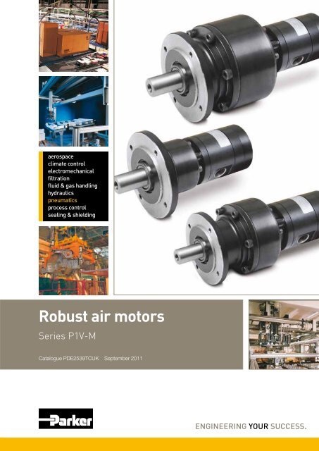
aerospaceclimate controlelectromechanicalfiltrationfluid & gas handlinghydraulicspneumaticsprocess controlsealing & shielding<strong>Robust</strong> air motorsSeries <strong>P1V</strong>-MCatalogue PDE2539TCUK September 2011
<strong>Robust</strong> air motors<strong>P1V</strong>-MFeatures <strong>Air</strong> Hydraulic Electric Electric Electricmotor motor motor motor motorregulated regulatedwithfeed backOverload safe *** *** * ** ***Increased torque at higher loads *** ** * ** ***Easy to limit torque *** *** * * ***Easy to vary speed *** *** * *** ***Easy to limit power *** *** * ** ***Reliability *** *** *** *** ***<strong>Robust</strong>ness *** *** * * *Installation cost *** * ** ** **Ease of service *** ** * * *Safety in damp environments *** *** * * *Safety in explosive atmospheres *** *** * * *Safety risk with electrical installations *** *** * * *Risk of oil leak *** * *** *** ***Hydraulic system required *** * *** *** ***Weight ** *** * ** *Power density ** *** * * *High torque for size ** *** * * *Noise level during operation * *** ** ** **Total energy consumption * ** *** *** ***Service interval * ** *** *** ***Compressor capacity required * *** *** *** ***Purchase price * * *** *** **Accuracy, speed * ** * ** ***Regulating dynamic * * * * ***Communication * * * *** **** = good, **=average, ***=excellentImportant!Before carrying out service activities, make surethe air motor is vented. Before disassembling themotor, disconnect the primary air hose to ensurethat the air supply is interrupted.NOTE!All technical data in the catalogue are typicalvalues.The air quality is a major factor in the service lifeof the motor, see ISO 8573-1.WARNINGFAILURE OR IMPROPER SELECTION OR IMPROPER USE OF THE PRODUCTS AND/OR SYSTEMS DESCRIBED HEREIN OR RELATED ITEMS CAN CAUSE DEATH, PERSONAL INJURY ANDPROPERTY DAMAGE.This document and other information from Parker Hannifin Corporation, its subsidiaries and authorized distributors provide product and/or system options for further investigation by users having technical expertise.It is important that you analyze all aspects of your application and review the information concerning the product or system in the current product catalog. Due to the variety of operating conditions and applicationsfor these products or systems, the user, through its own analysis and testing, is solely responsible for making the final selection of the products and systems and assuring that all performance, safety and warningrequirements of the application are met. The products described herein, including without limitation, product features, specifications, designs, availability and pricing, are subject to change by Parker HannifinCorporation and its subsidiaries at any time without notice.SALE CONDITIONSThe items described in this document are available for sale by Parker Hannifin Corporation, its subsidiaries or its authorized distributors. Any sale contract entered into by Parker will be governed by the provisionsstated in Parker’s standard terms and conditions of sale (copy available upon request).2Parker Hannifin CorporationPneumatic Division - Europe
<strong>Robust</strong> air motors<strong>P1V</strong>-MContentsPage<strong>Robust</strong> <strong>Air</strong> <strong>Motors</strong>, Series <strong>P1V</strong>-M ..............................................................4Principles of air motor function..................................................................6Torque, power and air consumption graphs..............................................6Correction diagram....................................................................................7Direction of motor rotation..........................................................................7Speed regulation.......................................................................................7<strong>Air</strong> supply...................................................................................................8Choice of components for air supply.........................................................8Silencing....................................................................................................9Sound levels..............................................................................................9CE marking................................................................................................9Compressed air quality............................................................................10Service interval........................................................................................10Choice of air motor..................................................................................11Technical data..........................................................................................12Order key.................................................................................................12Material specification...............................................................................12Permitted shaft loadings..........................................................................13Service kits for <strong>P1V</strong>-M motors..................................................................13Data for <strong>P1V</strong>-M020A, 200 watt motor with flange....................................14Data for <strong>P1V</strong>-M040A, 400 watt motor with flange....................................16Data for <strong>P1V</strong>-M060A, 600 watt motor with flange....................................18Dimensions, motors.................................................................................20Dimensions, foot brackets.......................................................................21Theoretical calculations......................................................................22-24<strong>P1V</strong>-M Service – Easier - Faster - Cheaper............................................25Torque, power and air consumption graphs............................................263Parker Hannifin CorporationPneumatic Division - Europe
<strong>Robust</strong> air motors<strong>P1V</strong>-MRemovable rear piece for easyreplacement of vanesCompressed airconnectionOne, two or three stageplanetary gearbox for awide range of applicationsMotor with 200,400 or 600Watts powerPainted planetarygearbox with flangemounting.<strong>Robust</strong> <strong>Air</strong> <strong>Motors</strong>, Series <strong>P1V</strong>-M<strong>P1V</strong>-M is a series of air motors, with planetary gearbox andmotor made of black varnished steel. Its robustness makes itsuitable for all normal air motor applications.The range contains three different sizes with power ratings of200, 400 or 600 Watts, shaft speeds ranging from 29 rpm to10000 rpm, and torques up to 401 Nm at maximum power (morethan 800 Nm torque if the motor is braked to stationary).The standard range includes a total of 27 versions, coveringall possible requirements for these power ratings.The motor and gearbox are built to be extremely strong,making the motors suitable for applications requiring considerablerobustness. The gearbox is of the planetary type, permanentlylubricated with grease. The flange mounting is cast asan integral part of the case, and give, together with the footbracket, plenty of opportunity for simple and robust installation.To extract high torques at low speeds, the gearboxes have beenmade strong enough to withstand motor braking to stationarywithout being damaged.A new design principle has made service activities quickerand easier than for any comparable motor. Servicing involvesloosening the screws holding the rear piece to the motor,removing the worn vanes from the back and inserting the newvanes.Unlike traditional air motors, there is no need to fully open the<strong>P1V</strong>-M for servicing, making the process much easier.<strong>P1V</strong>-M Service – Easier - Faster - Cheapersee page 254Parker Hannifin CorporationPneumatic Division - Europe
<strong>Robust</strong> air motors<strong>P1V</strong>-M<strong>Air</strong> motors have much smaller installation dimensions thancorresponding electric motors.<strong>Air</strong> motors can be stopped and started continually withoutdamage.The simple design principle of air motors makes them very easyto service.<strong>Air</strong> motors can be loaded until they stall, without damage.They are designed to be able to withstand the toughest heat,vibration, impact etc.The weight of an air motor is several times less thancorresponding electric motors.The motors are reversible as standard.<strong>Air</strong> motors can be used in the harshest environments.The reliability of air motors is very high, thanks to the design andthe low number of moving parts.5Parker Hannifin CorporationPneumatic Division - Europe
<strong>Robust</strong> air motorsPrinciples of air motor function25437Inlet left or outletright1 4 6Inlet right oroutlet left<strong>P1V</strong>-MTorque, power and air consumption graphsThe performance characteristics of each motor are shown inM [%]Q [%], P [%]20018016014012010080604020PQM1008060402020 40 60 80 100n [%]3The curve is for 6 barP = power Q = air consumptionM = torque n = speed21Possible working range of motor.1 Rotor cylinder2 Rotor3 Vanes4 End piece with bearing5 Mounting screw for motor6 Removable rear piece7 Pressure unloadingThere are a number of designs of air motor. Parker Pneumatichas chosen to use the vane rotor design, because of its simpledesign and reliable operation. The small external dimensions ofvane motors make them suitable for all applications.The principle of the vane motor is that a rotor with a numberof vanes is enclosed in a rotor cylinder. The motor is suppliedwith compressed air through one connection and air escapesfrom the other connection. The air pressure always bears atright angles against a surface. This means that the torque of themotor is a result of the vane surfaces and the air pressure.Optimum working range of motor.Higher speeds = more vane wearLower speeds with high torque = more gearboxweara family of curves as above, from which torque, power and airconsumption can be read off as a function of speed. Power iszero when the motor is stationary and also when running at freespeed (100%) with no load. Maximum power (100%) is normallydeveloped when the motor is braked to approximately half thefree speed (50%).Torque at free speed is zero, but increases as soon as a loadis applied, rising linearly until the motor stalls. As the motor canstop with the vanes in various positions, it is not possible tospecify an exact starting torque. However, a minimum startingtorque is shown in all tables.<strong>Air</strong> consumption is greatest at free speed, and decreases withdecreasing speed, as shown in the above diagram.Please refer to the curve on page 26for these pressures:3, 4, 5, 6 and 7 bar6Parker Hannifin CorporationPneumatic Division - Europe
<strong>Robust</strong> air motorsCorrection diagram1,31,21,11,00,90,80,70,60,50,40,33 4 5 6 7P = powerM = torqueQ = air consumptionn = speedP = f (p)M = f (p)Q = f (p)n = f (p)p [bar]Speed regulationM<strong>P1V</strong>-MSupply or exhaust throttling,non-reversible motorSupply throttling,reversible motorExhaust throttling,reversible motorTorque curvechange caused bythrottlingPressure regulation atmotor inlet.All catalogue data and curves are specified at a supply pres-Correction factorsure of 6 bar to the motor. This diagram shows the effect ofpressure on speed, specified torque, power and air consumption.Start off on the curve at the pressure used and then look up tothe lines for power, torque, air consumption or speed. Read offthe correction factor on the Y axis for each curve and multiplythis by the specified catalogue data in the table, or data readfrom the torque and power graphs.Example: at 4 bar supply pressure, the power is only0.55 x power at 6 bar supply pressure.This example shows how strongly power falls if supply pressureis reduced. You must therefore ensure that the motor is suppliedthrough pipes of sufficient diameter to avoid pressure drop.Direction of motor rotationThe direction of rotation of reversible motors is controlled bynlet, clockwiseOutlet, anticlockwiseInlet, anticlockwiseOutlet, clockwiseAnticlockwiseClockwisesupplying inlet L or inlet R with compressed air. The motor canbe stopped and started continually without damage occurring.MTorque curvechange caused bypressure changeThrottlingThe most common way to reduce the speed of a motor is toinstall a flow control valve in the air inlet. When the motor isused in applications where it must reverse and it is necessary torestrict the speed in both directions, flow control valves with bypassshould be used in both directions.Inlet throttlingIf the inlet air is restricted, the air supply is restricted and the freespeed of the motor falls, but there is full pressure on the vanes atlow speeds. This means that we get full torque from the motor atlow speeds despite the low air flow.Since the torque curve becomes “steeper”, this also meansthat we get a lower torque at any given speed than would bedeveloped at full air flow.Pressure regulationThe speed and torque can also be regulated by installing apressure regulator in the inlet pipe. This means that the motoris constantly supplied with air at lower pressure, which meansthat when the motor is braked, it develops a lower torque on theoutput shaft.In brief: Inlet throttling gives reduced speed in one directionbut maintains torque when braked. The torque curve becomessteeper. Pressure regulation in the inlet cuts torque when themotor is braked, and also reduces speed. The torque curve ismoved parallel.The direction of rotation of reversible motors is obtained bysupplying inlet L or inlet R with compressed air. The motor canbe stopped and started continually without damage occurring.7Parker Hannifin CorporationPneumatic Division - Europe
321425 1 33 1223 1<strong>Robust</strong> air motors<strong>Air</strong> supplyThe air supplying the motor must be filtered and regulated.Shut-off, filtering, pressure regulation and control valveReversible motor with 5/3 control valveReversible motor with two 3/2 control valvesDirectional valves are needed to provide it with air, to getthe motor to rotate when we want it to. These valves can beequipped with several means of actuation, such as electric,manual or pneumatic control. When the motor is used in anonreversible application, it is sufficient to use a 2/2 or 3/2 valvefor supply. Either one 5/3 or two 3/2 valves are needed for areversible motor, to ensure that the motor receives compressedair and the residual air outlet is vented. A flow control valve canbe installed in the supply pipe to regulate the motor speed if themotor is not used as a reversible motor. One flow control valvewith by-pass is needed to regulate each direction of rotation ifthe motor is used as a reversible motor. The built-in check valvewill then allow air from the residual air outlet to escape throughthe outlet port in the control valve.The compressed air supply must have sufficiently large pipesand valves to give the motor maximum power. The motor needs6 bar at the supply port all the time. A reduction of pressure to 5bar reduces the power developed to 77%, and to 55% at 4 bar.Choice of components for air supplySince the supply pressure at the air motor inlet port is of considerableimportance for obtaining the power, speed and torquequoted in the catalogue, the recommendations below should beobserved.The following data must be complied with:Supply pressure to air treatment unit:Min 7.5 barManometer pressure:6.7 barPipe length between air treatment unit and valve: max. 1 mPipe length between valve and air motor: max. 2 mThe pressure drop through air treatment unit - pipe -valve - pipe means that 6 bar pressure is obtained at themotor supply port.Please refer to the correction diagram on page 7, which showsthe effect of lower supply pressure in terms of power, speed andtorque.<strong>P1V</strong>-MThe table can be used as follows:If you are using only one motor with each air treatment unit andvalve, simply follow the table. If you are using more than onemotor with the same air treatment unit: r ead the table valuesfor selecting the air treatment unit and add them together, andselect a suitable air treatment unit from the table showing airflows per treatment unit. Then read the values for selecting thevalve from the bottom of the table, and select a suitable valvefrom the table showing air flows per valve family.The air treatment units have the following flows in Nl/Min at 7.5bar supply pressure and 0.8 bar pressure dropFRL series<strong>Air</strong> flow in Nl/MinP3H, Moduflex FRL, 40 Series, G1/4 550P3K, Moduflex FRL, 60 Series, G1/2 1310P3M, Moduflex FRL, 80 Series, G1 2770Standard series FRL, G11/2 9200Stainless series FRL PF, G1/4 530Stainless series FRL PF, G1/2 1480Valve series with respective flows in Nl/minuteValve seriesQn in Nl/MinValvetronic Solstar 33Interface PS1 100Adex A05 173Moduflex size 1, (2 x 3/2) 220Valvetronic PVL-B 5/3 closed centre, 6 mm push in 290Moduflex size 1, (4/2) 320B43 Manual and mechanical 340Valvetronic PVL-B 2 x 2/3, 6 mm push in 350Valvetronic PVL-B 5/3 closed centre, G1/8 370Compact Isomax DX02 385Valvetronic PVL-B 2 x 3/2 G1/8 440Valvetronic PVL-B 5/2, 6 mm push in 450Valvetronic PVL-B 5/3 vented centre, 6 mm push in 450Moduflex size 2, (2 x 3/2) 450Flowstar P2V-A 520Valvetronic PVL-B 5/3 vented centre, G1/8 540Valvetronic PVL-B 5/2, G1/8 540Valvetronic PVL-C 2 x 3/2, 8 mm push in 540Adex A12 560Valvetronic PVL-C 2 x 3/2 G1/8 570Compact Isomax DX01 585VIKING Xtreme P2LAX 660Valvetronic PVL-C 5/3 closed centre, 8 mm push in 700Valvetronic PVL-C 5/3 vented centre, G1/4 700B3-Series 780Valvetronic PVL-C 5/3 closed centre, G1/4 780Moduflex size 2, (4/2) 800Valvetronic PVL-C 5/2, 8 mm push in 840Valvetronic PVL-C 5/3 vented centre, 8 mm push in 840Valvetronic PVL-C 5/2, G1/4 840Flowstar P2V-B 1090ISOMAX DX1 1150B53 Manual and mechanical 1160B4-Series 1170VIKING Xtreme P2LBX 1290B5-Series, G1/4 1440<strong>Air</strong>line Isolator Valve VE22/23 1470ISOMAX DX2 2330VIKING Xtreme P2LCX, G3/8 2460VIKING Xtreme P2LDX, G1/2 2660ISOMAX DX3 4050<strong>Air</strong>line Isolator Valve VE42/43 5520<strong>Air</strong>line Isolator Valve VE82/83 136808Parker Hannifin CorporationPneumatic Division - Europe
<strong>Robust</strong> air motors<strong>P1V</strong>-MChoice of components for air supplyMotor <strong>P1V</strong>-M020 <strong>P1V</strong>-M040 <strong>P1V</strong>-M060<strong>Air</strong> flow required, Nl/s 6,5 9,5 15,0<strong>Air</strong> flow required, Nl/min 390 570 900Min. internal diameter of pipe, mm 10 12 12Choice of air treatment unit: recommended min. air flow in litres/minute at 7.5 bar air supply and 0.8 bar pressure drop430630990Choice of valve: recommended min. air flow in Qn in litres/minute(Qn is the flow through the valve at 6 bar supply pressure and 1 bar pressure drop over the valve).4706901080SilencingExhaust silencerCentral silencerThe noise from an air motor consists of both mechanical noiseand a pulsating noise from the air flowing out of the outlet. Theinstallation of the motor has a considerable effect on mechanicalnoise. It should be installed so that no mechanical resonanceeffects can occur. The outlet air creates a noise level which canamount to 115 dB(A) if the air is allowed to exhaust freely intothe atmosphere. Various types of exhaust silencers are used toreduce this level. The most common type screws directly ontothe exhaust port of the motor, and a wide range of versions isavailable made of sintered brass or sintered plastic. Since themotor function causes the exhaust air to pulsate, it is a goodidea to allow the air to exhaust into some kind of chamber first,which reduces the pulsations before they reach the silencer.The best silencing method is to connect a soft hose to a centralsilencer with the largest possible area, to reduce the speed ofthe out-flowing air as far as possible.CE markingThe air motors are supplied as “Components for installation” – theinstaller is responsible for ensuring that the motors are installed safelyin the overall system. Parker Pneumatic guarantees that its productsare safe, and as a supplier of pneumatic equipment we ensure thatthe equipment is designed and manufactured in accordance with theapplicable EU directive.Most of our products are classed as components as defined byvarious directives, and although we guarantee that the componentssatisfy the fundamental safety requirements of the directives to theextent that they are our responsibility, they do not usually carry the CEmark. Nevertheless, most <strong>P1V</strong>-S motors carry the CE mark becausethey are ATEX certified (for use in explosive atmospheres).The following are the currently applicable directives:• Machinery Directive(essential health and safety requirementsrelating to the design and structure of machines and safetycomponents)• EMC Directive• Simple Pressure Vessels Directive• Low Voltage Directive• ATEX Directive (ATEX = ATmosphere EXplosive)NOTE! Remember that if a silencer is too small or is blocked,back pressure is generated on the outlet side of the motor, whichin turn reduces the motor power.Sound levelsSound levels are measured at free speed with the measuring instrumentpositioned 1 m away from the air motor, see the table below<strong>Air</strong> Free With exhaust Exhaust air removedmotor exhaust silencer with pipes to anotherroomdB (A) dB (A) dB (A)<strong>P1V</strong>-M020 107 97 74<strong>P1V</strong>-M040 107 98 80<strong>P1V</strong>-M060 107 99 829Parker Hannifin CorporationPneumatic Division - Europe
<strong>Robust</strong> air motors<strong>P1V</strong>-MCompressed air qualityThe <strong>P1V</strong>-M motor is equipped with vanes for intermittent lubricationfree operation as standard, which is the most commonapplication of air motors.Working pressureMax 7 barWorking temperature -30 °C to +100 °CMedium40 µm filtered, oil mist ordry unlubricated compressed airDry unlubricated compressed airIf unlubricated compressed air is used, the compressed airshould comply with the purity standards below in order to guaranteethe longest possible overall service life. If the unlubricatedcompressed air has a high water content, condensation formsinside the motor, causing corrosion in all internal components. Aballbearing can be destroyed in a remarkably short time if it comesinto contact with a single water droplet.For indoor use, we recommend ISO8573-1 purity class 3.4.1. Toachieve this, compressors must be fitted with aftercoolers, oilfilters, refrigerant air dryers and air filters.For indoor/outdoor use, we recommend ISO8573-1 purity class1.2.1. To achieve this, compressors must be fitted with aftercoolers,oil filters, adsorption dryers and dust filters.Oil mistIf oil mist is used (approx. 1 drop of oil per m³ of compressed air),the oil not only acts as a lubricant but also protects against corrosion.This means that compressed air with a certain water contentmay be used without causing corrosion problems inside the motor.ISO8573-1 purity class 3.-.5 may be used without difficulty.ISO 8573-1 purity classesQuality Contaminants Water Oilclass particle max. con- max. pressure max. consizecentration dew point centration(µm) (mg/m³) (°C) (mg/m³)1 0,1 0,1 -70 0,012 1 1 -40 0,13 5 5 -20 1,04 15 8 +3 5,05 40 10 +7 256 - - +10 -For example: compressed air to purity class 3.4.3This means a 5 µm filter (standard filter), dew point +3 ºC (refrigerantcooled) and an oil concentration of 1,0 mg oil/m³ (assupplied by a standard compressor with a standard filter).Service intervalThe first service is due after approximately 500 hours of operation.After the first service, the service interval is determined by the degreeof vane wear*. The table below shows new dimensions and theminimum dimensions of worn vanes.X<strong>Air</strong> motor Dimensions Minimum dimensionson new vanes on vaneX [mm]X [mm]<strong>P1V</strong>-M020 8,5 6,5<strong>P1V</strong>-M040 7,0 5,0<strong>P1V</strong>-M060 8,0 6,0The following normal service intervals should be applied to in order toguarantee problem-free operation in air motors working continuously atload speeds*.Intermittent lubrication-free operation of motors with standardvanesDuty cycle : 70%Max. duration of intermittent use : 15 minutesFiltration 40 µm :750 hours of operation*Filtration 5 µm :1 000 hours of operation*Continuous operation of motors with standard vanes, with lubricationDuty cycle :ContinuousQuantity of oil :1 drop per m³ of airFiltration 40 µm :1 000 hours of operation*Filtration 5 µm :2 000 hours of operation*NOTE! The grease in the planetary gearbox must be checked once ina year and be changed if necessary. (Molycote BR2+)* The specified hours of operation applywhen the motor is running at the speed correspondingto maximum power (load speed).This is approximately half free speed.If the motor operates at higher speeds, theservice interval is shorter.If the motor operates at lower speeds, theservice interval is longer.10Parker Hannifin CorporationPneumatic Division - Europe
<strong>Robust</strong> air motors<strong>P1V</strong>-MChoice of air motorTorque at maximum power [Nm]500930020098100503098877766520654105435,03,0433222,0 11,02110,510,30,20,11 2 3 5 10 20 30 50 100 200 300 500 1000 2000 3000 5000 10000Speed at maximum power [rpm]The motor to be used should be selected by starting with thetorque needed at a specific shaft speed. In other words, tochoose the right motor, you have to know the required speedand torque. Since maximum power is reached at half themotor’s free speed, the motor should be chosen so that theoprating point is as close as possible to the maximum power ofthe motor.The design principle of the motor means that higher torque isgenerated when it is braked, which tends to increase the speed,etc. This means that the motor has a kind of speed self-regulationfunction built in.Use the above graph to choose the correct motor size. Thegraph contains the points for the maximum torque of each motorat maximum output. Add your operating point to the graph, thenselect a marked point above and to the right of your point.Then use the correct working diagram of the chosen motorto get more detailed technical data. Always select a motorwhose requisite technical data are in the shaded area. Also usethe correction diagram to find out what operation with differentsupply pressures would mean for the motor.Tip: Select a motor which is slightly too fast and powerful, thenregulate its speed and torque with a pressure regulator and/orthrottle to achieve the optimum working point.<strong>Air</strong> motors in diagram above1 <strong>P1V</strong>-M020A0A002 <strong>P1V</strong>-M020A02903 <strong>P1V</strong>-M020A01504 <strong>P1V</strong>-M020A00815 <strong>P1V</strong>-M020A00416 <strong>P1V</strong>-M020A00217 <strong>P1V</strong>-M020A00098 <strong>P1V</strong>-M020A00069 <strong>P1V</strong>-M020A0003Graph for each motor, please refer to page 151 <strong>P1V</strong>-M040A0A002 <strong>P1V</strong>-M040A02903 <strong>P1V</strong>-M040A01504 <strong>P1V</strong>-M040A00815 <strong>P1V</strong>-M040A00416 <strong>P1V</strong>-M040A00217 <strong>P1V</strong>-M040A00098 <strong>P1V</strong>-M040A00069 <strong>P1V</strong>-M040A0003Graph for each motor, please refer to page 171 <strong>P1V</strong>-M060A0A002 <strong>P1V</strong>-M060A02903 <strong>P1V</strong>-M060A01504 <strong>P1V</strong>-M060A00815 <strong>P1V</strong>-M060A00416 <strong>P1V</strong>-M060A00217 <strong>P1V</strong>-M060A00098 <strong>P1V</strong>-M060A00069 <strong>P1V</strong>-M060A0003Graph for each motor, please refer to page 1911Parker Hannifin CorporationPneumatic Division - Europe
<strong>Robust</strong> air motors<strong>P1V</strong>-MOrder keyP 1 V - M 0 2 0 A 0 A 0 0Motor size020 200 W040 400 W060 600 W<strong>Air</strong> motor range<strong>P1V</strong>-M <strong>Robust</strong> vane motorAFunctionIntegrated flange mountingVanes0 StandardFree speedper minA00 10000290 2890150 1466081 810041 413021 209009 90006 59003 30Possible combinationsPlease refer to pages 14 to 18Technical dataWorking pressureMax 7 barWorking temperature -30 °C to +100 °CMediumFiltered dry air and oil mist, purity classISO 8573-1 class 3.-.5 for indoor useand with a dew point lower thanambient temperature for outdoor use.Table and diagram dataAll values are typical values, with a tolerance of ±10%Material specificationPlanetary gearboxMotor housingShaftKeyExternal sealInternal steel partsGearbox lubricationPainted cast iron/AluminiumPainted steelHardened steelHardened steelFluor rubber, FPMHigh grade steelGrease<strong>P1V</strong>-M motors are of the vane type for intermittent lubricationfreeoperation. They can operate 70% of the time for up to 15minutes without lubrication. With lubrication, these motors canoperation 100% of the time.12Parker Hannifin CorporationPneumatic Division - Europe
<strong>Robust</strong> air motorsPermitted shaft loadingsBasic motorsMax. permitted load on output shaft for basic motors (based on10,000 rpm at input shaft with 90 % probable service life for ballbearings).<strong>P1V</strong>-MService kits for <strong>P1V</strong>-M motorsThe following kits are available for the basic motors, consistingof vanes and O-ring:Shaft with key slotOrder code Fax Frad a Bearingservice life[N] [N] [mm] [hours]Motor <strong>P1V</strong>-M0 0 •• A00Motor <strong>P1V</strong>-M0 0 •• 290Motor <strong>P1V</strong>-M0 • 0 •• 150High speed 93 140 15 2000093 120 15 3000093 110 15 40000Low speed 93 160 15 2000093 150 15 3000093 140 15 40000Motor <strong>P1V</strong>-M0 0 •• 081Motor <strong>P1V</strong>-M0 0 •• 041Motor <strong>P1V</strong>-M0 • 0 •• 021High speed 150 200 15 20000150 175 15 30000150 170 15 40000Low speed 260 345 15 20000260 290 15 30000260 275 15 40000Motor <strong>P1V</strong>-M0 0 •• 009Motor <strong>P1V</strong>-M0 0 •• 006Motor <strong>P1V</strong>-M0 • 0 •• 003High speed 450 625 15 20000450 550 15 30000450 500 15 40000Low speed 850 1000 15 20000850 1100 15 30000850 1250 15 40000F rad = Radial loading (N)F ax = Axial loading (N)Service kitFor motor<strong>P1V</strong>-M020<strong>P1V</strong>-M040<strong>P1V</strong>-M060Spare partsNew basic motors<strong>P1V</strong>-M020<strong>P1V</strong>-M040<strong>P1V</strong>-M060New gearboxes with flangeA0A00A0290A0150A0081A0041A0021A0009A0006A0003Order code<strong>P1V</strong>-6/831297A<strong>P1V</strong>-6/831298A<strong>P1V</strong>-6/831299AOrder code<strong>P1V</strong>-M020M<strong>P1V</strong>-M040M<strong>P1V</strong>-M060MOrder code<strong>P1V</strong>-MGA00<strong>P1V</strong>-MG290<strong>P1V</strong>-MG150<strong>P1V</strong>-MG081<strong>P1V</strong>-MG041<strong>P1V</strong>-MG021<strong>P1V</strong>-MG009<strong>P1V</strong>-MG006<strong>P1V</strong>-MG003FaxaFradFig 1: Load on output shaft for basic motor with shaft with key slot.13Parker Hannifin CorporationPneumatic Division - Europe
<strong>Robust</strong> air motors<strong>P1V</strong>-MNOTE! All technical data is basedon a working pressure of 6 bar.<strong>P1V</strong>-M020A0A00<strong>P1V</strong>-M020A0290<strong>P1V</strong>-M020A0150<strong>P1V</strong>-M020A0081<strong>P1V</strong>-M020A0041<strong>P1V</strong>-M020A0021<strong>P1V</strong>-M020A0009<strong>P1V</strong>-M020A0006<strong>P1V</strong>-M020A0003Data for <strong>P1V</strong>-M020A, 200 watt motor with flangeMax power Free Speed at Torque Min <strong>Air</strong> consump- Conn. Min pipe Weight Order codespeed max at max start tion at IDpower power torque max powerkW r/Min r/Min Nm Nm l/s mm Kg0,200 10 000 5 000 0,38 0,57 6,5 G1/8 10 1,94 <strong>P1V</strong>-M020A0A000,200 2 890 1 445 1,31 1,97 6,5 G1/8 10 1,94 <strong>P1V</strong>-M020A02900,200 1 466 733 2,59 3,89 6,5 G1/8 10 1,94 <strong>P1V</strong>-M020A01500,200 810 405 4,69 7,04 6,5 G1/8 10 2,94 <strong>P1V</strong>-M020A00810,200 413 206 9,20 13,81 6,5 G1/8 10 2,94 <strong>P1V</strong>-M020A00410,200 209 105 18,14 27,21 6,5 G1/8 10 2,94 <strong>P1V</strong>-M020A00210,200 90 45 42,34 63,50 6,5 G1/8 10 7,44 <strong>P1V</strong>-M020A00090,200 59 29 64,76 97,15 6,5 G1/8 10 7,44 <strong>P1V</strong>-M020A00060,200 30 15 126,99 190,48 6,5 G1/8 10 7,44 <strong>P1V</strong>-M020A0003Dimensions, see page 20Foot brackets, see page 21Permitted shaft loadings, see page 13Service kits, see page 1314Parker Hannifin CorporationPneumatic Division - Europe
<strong>Robust</strong> air motors<strong>P1V</strong>-M<strong>P1V</strong>-M020A0A00M, torque [Nm] P, power [W]<strong>P1V</strong>-M020A0290M, torque [Nm] P, power [W]<strong>P1V</strong>-M020A0150M, torque [Nm] P, power [W]3,060,8MP200175MP200MP2000,61502,015041501250,4100100100751,020,2505050252000 4000 6000 8000 10000750 1500 2250 3000300 600 900 1200 1500n, speed [rpm] n, speed [rpm] n, speed [rpm]<strong>P1V</strong>-M020A0081M, torque [Nm] P, power [W]<strong>P1V</strong>-M020A0041M, torque [Nm] P, power [W]<strong>P1V</strong>-M020A0021M, torque [Nm] P, power [W]9MP20020MP20040MP2006150151503015010010100201003505501050200 400 600 800 1000100 200 300 400 50050 100 150 200 250n, speed [rpm] n, speed [rpm] n, speed [rpm]<strong>P1V</strong>-M020A0009M, torque [Nm] P, power [W]<strong>P1V</strong>-M020A0006M, torque [Nm] P, power [W]<strong>P1V</strong>-M020A0003M, torque [Nm] P, power [W]80MP200120MP200240MP2006015090150180150401006010012010020503050605020 40 60 80 10020 40 6010 20 30n, speed [rpm] n, speed [rpm] n, speed [rpm]Possible working range of motor.Optimum working range of motor.Higher speeds = more vane wearLower speeds with high torque = more gearbox wear15Parker Hannifin CorporationPneumatic Division - Europe
<strong>Robust</strong> air motors<strong>P1V</strong>-MNOTE! All technical data is basedon a working pressure of 6 bar.<strong>P1V</strong>-M040A0A00<strong>P1V</strong>-M040A0290<strong>P1V</strong>-M040A0150<strong>P1V</strong>-M040A0081<strong>P1V</strong>-M040A0041<strong>P1V</strong>-M040A0021<strong>P1V</strong>-M040A0009<strong>P1V</strong>-M040A0006<strong>P1V</strong>-M040A0003Data for <strong>P1V</strong>-M040A, 400 watt motor with flangeMax power Free Speed at Torque Min <strong>Air</strong> consump- Conn. Min pipe Weight Order codespeed max at max start tion at IDpower power torque max powerkW r/Min r/Min Nm Nm l/s mm Kg0,400 10 000 5 000 0,76 1,15 9,5 G3/8 12 2,32 <strong>P1V</strong>-M040A0A000,400 2 890 1 445 2,63 3,98 9,5 G3/8 12 2,32 <strong>P1V</strong>-M040A02900,400 1 466 733 5,18 7,84 9,5 G3/8 12 2,32 <strong>P1V</strong>-M040A01500,400 810 405 9,39 14,20 9,5 G3/8 12 4,32 <strong>P1V</strong>-M040A00810,400 413 206 18,41 27,85 9,5 G3/8 12 4,32 <strong>P1V</strong>-M040A00410,400 209 105 36,28 54,90 9,5 G3/8 12 4,32 <strong>P1V</strong>-M040A00210,400 90 45 84,67 128,12 9,5 G3/8 12 7,82 <strong>P1V</strong>-M040A00090,400 59 29 129,53 195,99 9,5 G3/8 12 7,82 <strong>P1V</strong>-M040A00060,400 30 15 253,98 384,31 9,5 G3/8 12 7,82 <strong>P1V</strong>-M040A0003Dimensions, see page 20Foot brackets, see page 21Permitted shaft loadings, see page 13Service kits, see page 1316Parker Hannifin CorporationPneumatic Division - Europe
<strong>Robust</strong> air motors<strong>P1V</strong>-M<strong>P1V</strong>-M040A0A00M, torque [Nm] P, power [W]<strong>P1V</strong>-M040A0290M, torque [Nm] P, power [W]6,0<strong>P1V</strong>-M040A0150M, torque [Nm] P, power [W]121,6 0,8MP200175MP400MP4001,2 0,61504,030083001250,8 0,4100200200752,040,4 0,250100100252000 4000 6000 8000 10000750 1500 2250 3000300 600 900 1200 1500n, speed [rpm] n, speed [rpm] n, speed [rpm]<strong>P1V</strong>-M040A0081M, torque [Nm] P, power [W]18MP400<strong>P1V</strong>-M040A0041M, torque [Nm] P, power [W]40MP400<strong>P1V</strong>-M040A0021M, torque [Nm] P, power [W]n, speed [rpm]80MP400123003030060300200202004020061001010020100200 400 600 800 1000100 200 300 400 500n, speed [rpm] n, speed [rpm]50 100 150 200 250<strong>P1V</strong>-M040A0009M, torque [Nm] P, power [W]n, speed [rpm]<strong>P1V</strong>-M040A0006M, torque [Nm] P, power [W]n, speed [rpm]<strong>P1V</strong>-M040A0003M, torque [Nm] P, power [W]160MP400240MP400480MP40012030018030036030080200120200240200401006010012010020 40 60 80 1002040 601020 30n, speed [rpm]Possible working range of motor.Optimum working range of motor.Higher speeds = more vane wearLower speeds with high torque = more gearbox wear17Parker Hannifin CorporationPneumatic Division - Europe
<strong>Robust</strong> air motors<strong>P1V</strong>-MNOTE! All technical data is basedon a working pressure of 6 bar.<strong>P1V</strong>-M060A0A00<strong>P1V</strong>-M060A0290<strong>P1V</strong>-M060A0150<strong>P1V</strong>-M060A0081<strong>P1V</strong>-M060A0041<strong>P1V</strong>-M060A0021<strong>P1V</strong>-M060A0009<strong>P1V</strong>-M060A0006<strong>P1V</strong>-M060A0003Data for <strong>P1V</strong>-M060A, 600 watt motor with flangeMax power Free Speed at Torque Min <strong>Air</strong> consump- Conn. Min pipe Weight Order codespeed max at max start tion at IDpower power torque max powerkW r/Min r/Min Nm Nm l/s mm Kg0,600 10 000 5 000 1,14 1,71 15,0 G3/8 12 5,59 <strong>P1V</strong>-M060A0A000,600 2 890 1 445 3,94 5,92 15,0 G3/8 12 5,59 <strong>P1V</strong>-M060A02900,600 1 466 733 7,77 11,66 15,0 G3/8 12 5,59 <strong>P1V</strong>-M060A01500,600 810 405 14,08 21,12 15,0 G3/8 12 6,59 <strong>P1V</strong>-M060A00810,600 413 206 27,61 41,42 15,0 G3/8 12 6,59 <strong>P1V</strong>-M060A00410,600 209 105 54,42 81,64 15,0 G3/8 12 6,59 <strong>P1V</strong>-M060A00210,600 90 45 127,01 190,51 15,0 G3/8 12 11,09 <strong>P1V</strong>-M060A00090,600 59 29 194,29 291,44 15,0 G3/8 12 11,09 <strong>P1V</strong>-M060A00060,600 30 15 380,97 571,45 15,0 G3/8 12 11,09 <strong>P1V</strong>-M060A0003Dimensions, see page 20Foot brackets, see page 21Permitted shaft loadings, see page 13Service kits, see page 1318Parker Hannifin CorporationPneumatic Division - Europe
<strong>Robust</strong> air motors<strong>P1V</strong>-M<strong>P1V</strong>-M060A0A00M, torque [Nm] P, power [W]2,0 0,81,6 0,61,2 0,40,8 0,2MP200175150125100755025<strong>P1V</strong>-M060A0290M, torque [Nm] P, power [W]9,06,03,0MP600450300150<strong>P1V</strong>-M060A0150M, torque [Nm] P, power [W]161284MP6004503001502000 4000 6000 8000 10000750 1500 2250 3000300 600 900 1200 1500n, speed [rpm] n, speed [rpm] n, speed [rpm]<strong>P1V</strong>-M060A0081M, torque [Nm] P, power [W]n, speed [rpm]27M600P<strong>P1V</strong>-M060A0041M, torque [Nm] P, power [W]60MP600<strong>P1V</strong>-M060A0021M, torque [Nm] P, power [W]120MP60018450404508045030030030092040150150150200 400 600 800 1000100 200 300 400 50050 100 150 200 250n, speed [rpm] n, speed [rpm]<strong>P1V</strong>-M060A0009M, torque [Nm] P, power [W]240MP600<strong>P1V</strong>-M060A0006M, torque [Nm] P, power [W]n, speed [rpm]400MP600<strong>P1V</strong>-M060A0003M, torque [Nm] P, power [W]800MP6001604503004506004503002003004003008015010015020015020 40 60 80 1002040 601020 30n, speed [rpm] n, speed [rpm]Possible working range of motor.Optimum working range of motor.Higher speeds = more vane wearLower speeds with high torque = more gearbox wear19Parker Hannifin CorporationPneumatic Division - Europe
<strong>Robust</strong> air motors<strong>P1V</strong>-MDimensionsMotor <strong>P1V</strong>-M0 • 0A0A00Motor <strong>P1V</strong>-M0 • 0A0290Motor <strong>P1V</strong>-M0•0A01503Ø5,5 x 4LG45°5 P9Ø65G25 330Ø14 j716,3Ø60 h8Ø75Ø90LM8 35±1M5 x 12L1 ±1Motor <strong>P1V</strong>-M0 • 0A0081Motor <strong>P1V</strong>-M0 • 0A0041Motor <strong>P1V</strong>-M0 • 0A0021Ø5,5 x 445°LGL2 ±16 P925 321,5Ø90Ø65G30Ø19 j6Ø60 h8Ø75Ø90LM8 36 ±1M6 x 16Motor <strong>P1V</strong>-M0 • 0A0009Motor <strong>P1V</strong>-M0 • 0A0006Motor <strong>P1V</strong>-M0 • 0A0003Ø8,5 x 4L3 ±145°3LG8 P930 531,3Ø125Ø65GØ28 j6Ø80 h8Ø105Ø12540LM10 46 ±1M8 x 20Motor type G LG LM L1 L2 L3<strong>P1V</strong>-M020A G1/8 39,0 57,5 160,5 197,5 267,5<strong>P1V</strong>-M040A G3/8 49,0 77,5 180,5 217,5 287,5<strong>P1V</strong>-M060A G3/8 56,5 92,0 195,0 232,0 302,020Parker Hannifin CorporationPneumatic Division - Europe
<strong>Robust</strong> air motors<strong>P1V</strong>-MFoot brackets for <strong>P1V</strong>-MType For air motor Weight Order codeKgFoot bracket<strong>P1V</strong>-M0•0A0A00 0,63 <strong>P1V</strong>-MF1<strong>P1V</strong>-M0•0A0290<strong>P1V</strong>-M0•0A0150<strong>P1V</strong>-M0•0A0081<strong>P1V</strong>-M0•0A0041<strong>P1V</strong>-M0•0A0021<strong>P1V</strong>-M0•0A0009 1,70 <strong>P1V</strong>-MF2<strong>P1V</strong>-M0•0A0006<strong>P1V</strong>-M0•0A0003All brackets supplied with fastening screws for the motor.Dimensions<strong>P1V</strong>-MF13424 61157070908Ø8,5 (2x)5035 10<strong>P1V</strong>-MF2162,51001290125Ø12,5 (2x)21Parker Hannifin CorporationPneumatic Division - Europe
<strong>Robust</strong> air motorsTheoretical calculationsThis section provides you with the background you need inorder to select the right air motor for common applications.The first four parts explain the direct physical relationshipsbetween:Force - Torque - Speed - Power RequirementBefore selecting an air motor, you need to know the torquerequired by the application at the necessary speed. Sometimes,the torque and the speed are not known but the power requirementand the speed of movement are. You can use the followingformulas to calculate the speed and torque.PowerThe power requirement is always calculated in N.Formula:F = m x gF = power in Nm = mass in kgg = gravitation (9,81) in m/s 2In this example, the mass is 150 kgF = 150 x 9,81 NF = 1470 NTorqueTorque is the force applied to produce rotational motion (rotationalforce) or the force applied in the opposite direction. It isthe product of the rotational force F and the distance from thepivot point (radius or moment arm)Formula:M = m x g x rM = torque in Nmm = mass in kgg = gravitation (9,81) in m/s 2r = radius or moment arm in mrF150 kgM150 kg<strong>P1V</strong>-MSpeedThe required motor speed can be calculated if the speed ofmovement and the radius (diameter) are known.n = v x 60/(2 x π x r)n = motor speed in rpmv = speed of movement in m/secr = radius in mπ = constant (3,14)In this example, the speed of movement is 1,5 m/sand the drum diameter is 300 m (radius r = 0,15 m)n = 1,5 x 60/(2 x π x 0,15) rpmn = 96 rpmPower RequirementThe power requirement can be calculated if the motor speedand torque are known.P = M x n/9550P = power in kWM = torque in Nmn = rpm9550 = conversion factorIn this example, a torque of 1,25 Nm is requiredat a speed of 1500 rpm.P = 1,25 x 1500/9550P = 0,196 kW or approx. 200 WattrvnM, nIn this example, the drum diameter is 300 mm, whichmeans the radius r = 0,15 m, and the mass is 150kg.M = 150 x 9,81 x 0,15 NmM = 221 Nm22Parker Hannifin CorporationPneumatic Division - Europe
<strong>Robust</strong> air motorsFrictional Forces between two ObjectsA frictional force always occurs between two objects withsurfaces in contact with each other. It is always exerted againstthe direction of movement.The frictional force is either static or kinetic. When selecting anair motor, we need to consider the larger of the two forces, staticor kinetic.The size of the static frictional force or the kinetic frictional forceis the product of the normal force F n and the coefficient of staticfriction (µ 0 ), or the product of the normal force F n and the coefficientof kinetic friction (µ).The size of the contact surface between the objects is irrelevant.Formula:F static = F n x µ 0F kinetic = F n x µF n = m x gF n FfrictionF staticF kinetic<strong>P1V</strong>-MMaterial Coefficient of kinetic friction µDry LubricatedBronze Bronze 0,2 0,06Bronze Grey iron 0,21 0,08Grey iron Grey iron - 0,12Steel Bronze 0,18 0,07Steel Ice 0,014 -Steel Grey iron 0,16 0,05Steel Steel 0,10 0,05Steel White metal 0,20 0,04Wood Ice 0,035 -Wood Wood 0,35 0,05Leather Grey iron 0,28 0,12Brake lining Steel 0,55 0,40Steel Nylon (polyamide) 0,5 0,10Example: A steel component with a weight of 500 kg is to bepulled across bronze plate without lubrication. What will the frictionalforce be when the component moves?F static = F n x µ 0F kinetic = F n x µF static = 500 x 9,81 x 0,27 = 1324 NF kinetic = 500 x 9,81 x 0,18 = 883 NThe static frictional force should always be compared with theforce provided by the motor when it starts.F static = static friction in NF kinetic = kinetic friction in NF n = force from object in Nm = mass in kgg = gravitation (9,81) in m/s 2Kinetic ResistanceKinetic resistance is a term expressing the total resistance,consisting of rolling resistance and the frictional force in thebearingF nF FMaterial Coefficient of static friction µ 0Dry LubricatedBronze Bronze 0,28 0,11Bronze Grey iron 0,28 0,16Grey iron Grey iron - 0,16Steel Bronze 0,27 0,11Steel Ice 0,027 -Steel Grey iron 0,20 0,10Steel Steel 0,15 0,10Steel White metal - -Wood Ice - -Wood Wood 0,65 0,16Leather Grey iron 0,55 0,22Brake lining Steel - -Steel Nylon (polyamide) - -Formula:F F = µ F x F nF F = kinetic resistance in Nµ F = coefficient of kinetic resistancen = force from object in NFCoefficient of kinetic resistance:ObjectCoefficient of kineticresistanceRailway vehicle on steel rails 0,0015 to 0,0030Vehicle with rubber wheel on asphalt 0,015 to 0,03Example:A railway carriage with a weight of 2 tonnes is to move over flatrails. What will the kinetic resistance be?F F = µ F x F nF F = 0,0030 x 2 x 1000 x 9,81F F = 4,86 N23Parker Hannifin CorporationPneumatic Division - Europe
<strong>Robust</strong> air motors<strong>P1V</strong>-MMoving a component over a base, with friction betweenthemMoving a carriage over rails, with kinetic resistancebetween themF nF nFFF totaltaammF kinetic resistanceF frictionFF accaccThe force required to move the component consists of two partsThe force required to move the component consists of two parts - a kinetic resistance to move the component over the base, and- a frictional force to move the component over the base, and an an acceleration forceacceleration forceF tot = F kinetic resistance + F accF tot = F friction + F accF acc = m x aF tot = F friction + m x aF tot = the total force required in order to move the object in NF friction = frictional force in N (either F static or F kinetic depending onwhich is the greater force)F acc = acceleration force in Nm = mass in kga = acceleration in m/s 2F acc = m x aF tot = F kinetic resistance + m x aF tot = the total force required in order to move the object in NF kinetic resistance = total kinetic resistance in NF acc = acceleration force in Nm = mass in kga = acceleration in m/s 2A steel component weighing 500 kg is to be pulled over a drysteel plate with an acceleration of 0,1 m/s 2. What is the total forcerequired to produce this movement?A carriage weighing 2500 kg is to be pulled over steel rails withan acceleration of 0,2 m/s 2. What is the total force required toproduce this movement?F tot = F kinetic resistance + F accF tot = F kinetic + F accF tot = F kinetic + m x aF tot = Fn x u + m x aF tot = 500 x 9,81 x 0,15 + 500 x 0,1F tot = 735,75 + 50F tot = 785,75 NAnswer: A force of 780 N is required to produce this movement.F tot = u F x F N + m x aF tot = 0,0030 x 2500 x 9,81 + 2500 x 0,2F tot = 6,1 + 500F tot = 506 NAnswer: A force of 510 N is required to produce this movement.In practiceThese calculations only produce values as they would be underoptimum conditions. There must be no inclines in either direction.In applications using carriages, the rails must be perfectlyflat without any inclines, the wheels must be perfectly round andthere must be nothing on the rails (grains of sand, etc.). Theremust also be no effects from wind, etc.In addition, there is always uncertainty with regard to thecompressed air supply. How can we guarantee a pressure of6 bar to the inlet port of the air motor?Tip: calculate the required theoretical values for the air motorand assume a safety factor of 10 for the frictional force or kineticresistance, and add this to the acceleration force. If the motorproves to be too powerful in practice, the supply air can alwaysbe regulated by throttling or pressure regulation. If you select amotor that is not powerful enough, on the other hand, the onlyoption is to replace it.24Parker Hannifin CorporationPneumatic Division - Europe
<strong>Robust</strong> air motors<strong>P1V</strong>-M<strong>P1V</strong>-M Service – Easier - Faster - CheaperReplacing vanes - step by step.Step 1.Remove the rear piece.Repeat steps 3 and 4 until all the vanes have been replaced.Step 5.Replace the inspection plug.Step 2.Remove the inspection plug.Step 6.Replace the rear piece.Step 3.Use a screwdriver to rotate the motor until you can see a vane inthe centre of the inspection hole.Replacing vanes with motor still fitted to the machineThe <strong>P1V</strong>-M motor has been developed to allow the vanes tobe replaced without the need to remove the motor from themachine. This makes vane replacement easier, quicker andcheaper, while minimising stoppages.Service intervals are described on page 10.Step 4.Remove the old vane and replace it with a new one.25Parker Hannifin CorporationPneumatic Division - Europe
<strong>Robust</strong> air motors<strong>P1V</strong>-MTorque, power and air consumption graphsM [%]240Q [%], P [%]120220200180MPQ1001608014012060100804060402020P = powerM = torque207 bar6 bar5 bar4 bar3 bar40Q = air consumptionn = speed60 80 100n [%]The curves in this graph are a combination of the torque, power andair consumption graphs on page 6. The values from the correctiondiagram on page 7 have also been used for the curves for the differentpressure values. The graph also shows that is it very important toensure that the pressure supplied to the inlet port of the motor iscorrect, in order to allow the motor to work at maximum capacity. Ifthe valve supplying a large motor is too small, or if the supply line isunderspecified, the pressure at the inlet port may be so low that themotor is unable to do its work. One solution would be to upgrade thevalve and supply system, or alternatively you could replace the motorwith a smaller motor with lower air consumption. The result would beincreased pressure at the inlet port, which means that the smallermotor could carry out the necessary work. However, you may need toselect a smaller motor with a lower free speed in order to obtain sufficienttorque at the outgoing shaft.26Parker Hannifin CorporationPneumatic Division - Europe
<strong>Robust</strong> air motors<strong>P1V</strong>-M27Parker Hannifin CorporationPneumatic Division - Europe
Parker WorldwideEurope, Middle East, AfricaAE – United Arab Emirates,DubaiTel: +971 4 8127100parker.me@parker.comAT – Austria, Wiener NeustadtTel: +43 (0)2622 23501-0parker.austria@parker.comAT – Eastern Europe, WienerNeustadtTel: +43 (0)2622 23501 900parker.easteurope@parker.comAZ – Azerbaijan, BakuTel: +994 50 2233 458parker.azerbaijan@parker.comBE/LU – Belgium, NivellesTel: +32 (0)67 280 900parker.belgium@parker.comBY – Belarus, MinskTel: +375 17 209 9399parker.belarus@parker.comCH – Switzerland, EtoyTel: +41 (0)21 821 87 00parker.switzerland@parker.comCZ – Czech Republic, KlecanyTel: +420 284 083 111parker.czechrepublic@parker.comDE – Germany, KaarstTel: +49 (0)2131 4016 0parker.germany@parker.comDK – Denmark, BallerupTel: +45 43 56 04 00parker.denmark@parker.comES – Spain, MadridTel: +34 902 330 001parker.spain@parker.comFI – Finland, VantaaTel: +358 (0)20 753 2500parker.finland@parker.comFR – France, Contamine s/ArveTel: +33 (0)4 50 25 80 25parker.france@parker.comGR – Greece, AthensTel: +30 210 933 6450parker.greece@parker.comHU – Hungary, BudapestTel: +36 1 220 4155parker.hungary@parker.com© 2011 Parker Hannifin Corporation. All rights reserved.IE – Ireland, DublinTel: +353 (0)1 466 6370parker.ireland@parker.comIT – Italy, Corsico (MI)Tel: +39 02 45 19 21parker.italy@parker.comKZ – Kazakhstan, AlmatyTel: +7 7272 505 800parker.easteurope@parker.comNL – The Netherlands, OldenzaalTel: +31 (0)541 585 000parker.nl@parker.comNO – Norway, AskerTel: +47 66 75 34 00parker.norway@parker.comPL – Poland, WarsawTel: +48 (0)22 573 24 00parker.poland@parker.comPT – Portugal, Leca da PalmeiraTel: +351 22 999 7360parker.portugal@parker.comRO – Romania, BucharestTel: +40 21 252 1382parker.romania@parker.comRU – Russia, MoscowTel: +7 495 645-2156parker.russia@parker.comSE – Sweden, SpångaTel: +46 (0)8 59 79 50 00parker.sweden@parker.comSK – Slovakia, Banská BystricaTel: +421 484 162 252parker.slovakia@parker.comSL – Slovenia, Novo MestoTel: +386 7 337 6650parker.slovenia@parker.comTR – Turkey, IstanbulTel: +90 216 4997081parker.turkey@parker.comUA – Ukraine, KievTel +380 44 494 2731parker.ukraine@parker.comUK – United Kingdom, WarwickTel: +44 (0)1926 317 878parker.uk@parker.comZA – South Africa, Kempton ParkTel: +27 (0)11 961 0700parker.southafrica@parker.comParker Hannifin Manufacturing LtdPneumatic Division EuropeThe Collins Centre,Lichfield South, Wall Island,Birmingham Road, Lichfield.WS14 0QP United KingdomTel.: +44 (0) 1543 483800Fax: +44 (0) 1543 483801www.parker.comNorth AmericaCA – Canada, Milton, OntarioTel: +1 905 693 3000US – USA, ClevelandTel: +1 216 896 3000Asia PacificAU – Australia, Castle HillTel: +61 (0)2-9634 7777CN – China, ShanghaiTel: +86 21 2899 5000HK – Hong KongTel: +852 2428 8008IN – India, MumbaiTel: +91 22 6513 7081-85JP – Japan, TokyoTel: +81 (0)3 6408 3901KR – South Korea, SeoulTel: +82 2 559 0400MY – Malaysia, Shah AlamTel: +60 3 7849 0800NZ – New Zealand, Mt WellingtonTel: +64 9 574 1744SG – SingaporeTel: +65 6887 6300TH – Thailand, BangkokTel: +662 186 7000 99TW – Taiwan, TaipeiTel: +886 2 2298 8987South AmericaAR – Argentina, Buenos <strong>Air</strong>esTel: +54 3327 44 4129BR – Brazil, Sao Jose dos CamposTel: +55 800 727 5374CL – Chile, SantiagoTel: +56 2 623 1216MX – Mexico, ApodacaTel: +52 81 8156 6000European Product Information CentreFree phone: 00 800 27 27 5374(from AT, BE, CH, CZ, DE, DK, EE, ES, FI,FR, IE, IL, IS, IT, LU, MT, NL, NO, PL, PT, RU,SE, SK, UK, ZA)Catalogue PDE2539TCUK September 2011Your local authorized Parker distributor