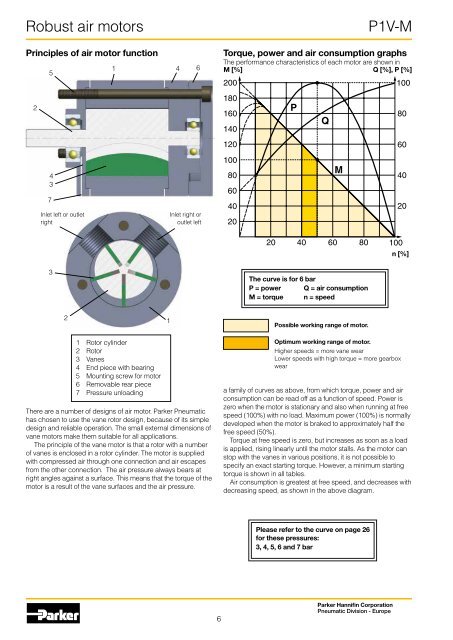
<strong>Robust</strong> air motorsPrinciples of air motor function25437Inlet left or outletright1 4 6Inlet right oroutlet left<strong>P1V</strong>-MTorque, power and air consumption graphsThe performance characteristics of each motor are shown inM [%]Q [%], P [%]20018016014012010080604020PQM1008060402020 40 60 80 100n [%]3The curve is for 6 barP = power Q = air consumptionM = torque n = speed21Possible working range of motor.1 Rotor cylinder2 Rotor3 Vanes4 End piece with bearing5 Mounting screw for motor6 Removable rear piece7 Pressure unloadingThere are a number of designs of air motor. Parker Pneumatichas chosen to use the vane rotor design, because of its simpledesign and reliable operation. The small external dimensions ofvane motors make them suitable for all applications.The principle of the vane motor is that a rotor with a numberof vanes is enclosed in a rotor cylinder. The motor is suppliedwith compressed air through one connection and air escapesfrom the other connection. The air pressure always bears atright angles against a surface. This means that the torque of themotor is a result of the vane surfaces and the air pressure.Optimum working range of motor.Higher speeds = more vane wearLower speeds with high torque = more gearboxweara family of curves as above, from which torque, power and airconsumption can be read off as a function of speed. Power iszero when the motor is stationary and also when running at freespeed (100%) with no load. Maximum power (100%) is normallydeveloped when the motor is braked to approximately half thefree speed (50%).Torque at free speed is zero, but increases as soon as a loadis applied, rising linearly until the motor stalls. As the motor canstop with the vanes in various positions, it is not possible tospecify an exact starting torque. However, a minimum startingtorque is shown in all tables.<strong>Air</strong> consumption is greatest at free speed, and decreases withdecreasing speed, as shown in the above diagram.Please refer to the curve on page 26for these pressures:3, 4, 5, 6 and 7 bar6Parker Hannifin CorporationPneumatic Division - Europe
<strong>Robust</strong> air motorsCorrection diagram1,31,21,11,00,90,80,70,60,50,40,33 4 5 6 7P = powerM = torqueQ = air consumptionn = speedP = f (p)M = f (p)Q = f (p)n = f (p)p [bar]Speed regulationM<strong>P1V</strong>-MSupply or exhaust throttling,non-reversible motorSupply throttling,reversible motorExhaust throttling,reversible motorTorque curvechange caused bythrottlingPressure regulation atmotor inlet.All catalogue data and curves are specified at a supply pres-Correction factorsure of 6 bar to the motor. This diagram shows the effect ofpressure on speed, specified torque, power and air consumption.Start off on the curve at the pressure used and then look up tothe lines for power, torque, air consumption or speed. Read offthe correction factor on the Y axis for each curve and multiplythis by the specified catalogue data in the table, or data readfrom the torque and power graphs.Example: at 4 bar supply pressure, the power is only0.55 x power at 6 bar supply pressure.This example shows how strongly power falls if supply pressureis reduced. You must therefore ensure that the motor is suppliedthrough pipes of sufficient diameter to avoid pressure drop.Direction of motor rotationThe direction of rotation of reversible motors is controlled bynlet, clockwiseOutlet, anticlockwiseInlet, anticlockwiseOutlet, clockwiseAnticlockwiseClockwisesupplying inlet L or inlet R with compressed air. The motor canbe stopped and started continually without damage occurring.MTorque curvechange caused bypressure changeThrottlingThe most common way to reduce the speed of a motor is toinstall a flow control valve in the air inlet. When the motor isused in applications where it must reverse and it is necessary torestrict the speed in both directions, flow control valves with bypassshould be used in both directions.Inlet throttlingIf the inlet air is restricted, the air supply is restricted and the freespeed of the motor falls, but there is full pressure on the vanes atlow speeds. This means that we get full torque from the motor atlow speeds despite the low air flow.Since the torque curve becomes “steeper”, this also meansthat we get a lower torque at any given speed than would bedeveloped at full air flow.Pressure regulationThe speed and torque can also be regulated by installing apressure regulator in the inlet pipe. This means that the motoris constantly supplied with air at lower pressure, which meansthat when the motor is braked, it develops a lower torque on theoutput shaft.In brief: Inlet throttling gives reduced speed in one directionbut maintains torque when braked. The torque curve becomessteeper. Pressure regulation in the inlet cuts torque when themotor is braked, and also reduces speed. The torque curve ismoved parallel.The direction of rotation of reversible motors is obtained bysupplying inlet L or inlet R with compressed air. The motor canbe stopped and started continually without damage occurring.7Parker Hannifin CorporationPneumatic Division - Europe