BETABITE HYDRAULICS - Duncan Rogers
BETABITE HYDRAULICS - Duncan Rogers
BETABITE HYDRAULICS - Duncan Rogers

Create successful ePaper yourself
Turn your PDF publications into a flip-book with our unique Google optimized e-Paper software.
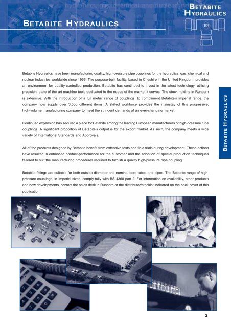
<strong>BETABITE</strong> <strong>HYDRAULICS</strong>Betabite Hydraulics have been manufacturing quality, high-pressure pipe couplings for the hydraulics, gas, chemical andnuclear industries worldwide since 1966. The purpose-built facility, based in Cheshire in the United Kingdom, providesan environment for quality-controlled production. Betabite has continued to invest in the latest technology, utilisingprecision, state-of-the-art machine-tools dedicated to the needs of the market it serves. The stock-holding in Runcornis extensive. With the introduction of a full metric range of couplings, to compliment Betabite’s Imperial range, thecompany now supply over 3,500 different items. A skilled workforce provides the mainstay of this progressive,high-volume manufacturing company to meet the stringent demands of an ever-changing market.Continued expansion has secured a place for Betabite among the leading European manufacturers of high-pressure tubecouplings. A significant proportion of Betabite’s output is for the export market. As such, the company meets a widevariety of International Standards and Approvals.All of the products designed by Betabite benefit from extensive tests and field trials during development. These actionshave resulted in enhanced product-performance for the customer and the adoption of special production techniquestailored to suit the manufacturing procedures required to furnish a quality high-pressure pipe coupling.<strong>BETABITE</strong> <strong>HYDRAULICS</strong>Betabite fittings are suitable for both outside diameter and nominal bore tubes and pipes. The Betabite range of highpressurecouplings, in Imperial sizes, comply fully with BS 4368 part 2. For information on availability, other productsand new developments, contact the sales desk in Runcorn or the distributor/stockist indicated on the back cover of thispublication.2
THE <strong>BETABITE</strong> PRINCIPLENutCoupling BodyTHE <strong>BETABITE</strong> PRINCIPLETubeFerrule Secondary Bite Primary BiteAs the coupling nut is tightened, the ferrule moves along the tube. When the ferrule outside diameter contacts the innertaper of the coupling body, the front cutting edge (1) of the ferrule makes the primary “bite” cleanly into the outer surfaceof the tube. At the point where the secondary “bite” (2) comes into contact with the surface of the tube, a sharp increasein torque will occur. This signals to the operative that a perfect, pressure-tight joint has been achieved and no furthertightening is necessary. At the same time, the ferrule is clamped firmly by the nut on the tube (3) providing a perfect antivibrationlock.ADVANTAGES OF THE <strong>BETABITE</strong> PRINCIPLEBBTHREE POINT CONTACT WITH OUTSIDE DIAMETER OF TUBE.BBSUPERIOR SEALING QUALITIES.BBTHE OPERATIVE WILL “FEEL” WHEN A PERFECT JOINT HAS BEEN MADE.BBREMOVES POSSIBILITY OF OVERTIGHTENING.BBAVOIDS NARROWING OR “NECKING” OF THIN-WALL TUBES.BBJOINT MAY BE BROKEN AND RE-MADE REPEATEDLY.3
USEFUL DATA - METRIC ODPERFORMANCEBetabite manufactures two series of metric coupling, L (light), S (heavy). The performance of both series aresummarised in the following table, where it is possible to see the values of operating pressures for each range ofouter diameter for the pipes employed. It must be taken into account that the pressure values indicated arecalculated considering a safety factor of 4 vs. those obtained during static operating tests at 120ºC.SeriesOutsideØ of pipeNominal PressureL (light) 6 to 18 mm 315 bar22 to 42 mm 160 barUSEFUL DATAS (heavy) 6 to 14 mm 630 bar16 to 30 mm 400 bar38 mm 315 barTECHNICAL AND CONSTRUCTION CHARACTERISTICSAll metric couplings are manufactured in accordance with DIN 2353, with either conical(DIN3858 - DIN158 - NPT) or cylindrical (UNI ISO 228 - UNF - UNI 4535) threading.Contrary to the conical threading, which produces the seal by direct coupling, the seal for cylindrical threading isobtained by three methods:a). Using Dowty seal or copper washer to DIN3852, Form A (fig 1).b). Fitting body incorporating cutting edges to DIN3852, Form B (fig 2).c). The fitting of a perbunan or viton ring (soft seal) to DIN3852, form E (fig 3).Fig 1. Fig 2. Fig 3.Form A Form B Form EAll components are manufactured from either drawn or pressed steel (both by the cold and hot treatmentsystem). The units and the nuts are submitted to a corrosion - proof surface treatment(yellow passivated UNI ISO 2081 - 4520).The cutting rings are submitted both to a heat treatment which enhances their mechanical characteristics leavingalmost unchanged elasticity, and to a corrosion proof surface treatment. Fittings are manufactured in bothcarbon and stainless steel.4
USEFUL DATA - METRIC ODRecommendations for tubesFor Betabite steel fittings we recommend a tube according to DIN 2391/C of material of special quality (St. 35.4),protective-gas/special-clean-annealed, free of scale (NBK).USEFUL DATATubeo.d.mmWallthicknessmmTubei.d.mmDesignpressure 1 )barWeightKg/m5 0.75 3.5 376 0.0835 1 3 432 0.0996 0.75 4.5 333 0.1036 1 4 389 0.1236 1.5 3 549 0.1666 2 2 692 0.1976 2.25 1.5 757 0.2088 1 6 333 0.1738 1.5 5 431 0.2408 2 4 549 0.2968 2.5 3 658 0.33910 1 8 282 0.22210 1.5 7 373 0.31410 2 6 478 0.39510 2.5 5 576 0.46210 3 4 666 0.518Tubeo.d.mmWallthicknessmmTubei.d.mmDesignpressure 1 )barWeightKg/m20 1.5 17 212 0.68420 2 16 282 0.88820 2.5 15 353 1.07920 3 14 373 1.25820 3.5 13 426 1.42420 4 12 478 1.57822 1 20 128 0.51822 1.5 19 192 0.75822 2 18 256 0.98622 2.5 17 320 1.20222 3 16 385 1.40625 2 21 226 1.13425 2.5 20 282 1.38725 3 19 338 1.62825 4 17 394 2.07225 4.5 16 437 2.27525 5 15 478 2.46612 1 10 235 0.27112 1.5 9 353 0.38812 2 8 409 0.49312 2.5 7 495 0.58612 3 6 576 0.66612 3.5 5 651 0.73414 1 12 201 0.32114 1.5 11 302 0.46214 2 10 403 0.59214 2.5 9 434 0.70914 3 8 507 0.81414 3.5 7 576 0.90614 4 6 641 0.98615 1 13 188 0.34515 1.5 11 282 0.49915 2 11 376 0.64115 2.5 10 409 0.77115 3 9 478 0.88816 1 14 176 0.37016 1.5 13 264 0.53616 2 12 353 0.69116 2.5 11 386 0.83216 3 10 452 0.96218 1 16 157 0.41918 1.5 15 235 0.61018 2 14 313 0.78918 2.5 13 392 0.95618 3 12 409 1.11028 1.5 25 151 0.98028 2 24 201 1.28228 2.5 23 252 1.57228 3 22 302 1.85028 4 20 403 2.36828 5 18 434 2.83630 2 26 188 1.38130 2.5 25 235 1.69530 3 24 282 1.99830 4 22 376 2.56530 5 20 409 3.08335 2 31 161 1.62835 2.5 30 201 2.00435 3 29 242 2.36735 4 27 322 3.05835 5 25 403 3.69935 6 23 419 4.29138 2.5 33 186 2.18938 3 32 223 2.58938 4 30 297 3.35438 5 28 371 4.06938 6 26 390 4.73538 7 24 446 5.35242 2 38 134 1.97342 3 36 201 2.88542 4 34 269 3.7491) Based on the following values the design pressure has beencalculated according to DIN 2413 validity l5Part numbers indicated are for Carbon Steel Couplings only.For 316 Stainless Steel Couplings, add suffix SS to part number.
USEFUL DATAFOR IMPERIAL O.D. TUBES1. 2.Outside Dia.of TubeMinimum WallThicknessOutside Dia.of TubeMinimum WallThickness1⁄4" to 3 ⁄8"1⁄2" to 5 ⁄8"3⁄4" to 1 1 ⁄4"1 1 ⁄2"20 sg. .036"18 sg. .048"16 sg. .064"14 sg. .080"1⁄4" to 1 ⁄2"5⁄8" to 1"1 1 ⁄4" to 1 1 ⁄2"16 sg. .064"14 sg. .080"12 sg. .104"USEFUL DATABetabite couplings may be used with either steel or copper tubes, but where high vibration stresses areinvolved, the use of copper tube is not recommended and a heavier gauge of steel tube is preferred. Twotables are shown giving details of tube wall thicknesses. 1, minimum wall thickness for which Betabitecouplings are suitable (either steel or copper tubes) and 2, recommended minimum wall thicknesses wherehigh vibration stresses are involved (steel tubes only).Betabite couplings are suitable for the following working pressures – up to and including:1" O.D. 690 bar (10,000 P.S.I.) hydraulic or 345 bar (5,000 P.S.I.) gas;1 1 ⁄4" O.D. 552 bar (8,000 P.S.I.) hydraulic or 276 bar (4,000 P.S.I.) gas;1 1 ⁄2" O.D. 414 bar (6,000 P.S.I.) hydraulic or 207 bar (3,000 P.S.I.) gas.Please note that the pressures for which Betabite couplings are suitable does not necessarily relate to thetube wall thickness tables listed above. Tubes of heavier gauge should be used for higher pressures andadverse working conditions.O.D. tubes are manufactured to close tolerances with a wide range of available sizes and a good surfacefinish, and are eminently suitable for use with Betabite couplings.Part numbers indicated are for Carbon Steel Couplings only.For 316 Stainless Steel Couplings, add suffix SS to part number.6
USEFUL DATAFOR IMPERIAL N.B. TUBESBasic dimensions of Nominal Bore Tubes.Nominal Fractional Max. Min.Bore Outside Dia. Dia. Dia.USEFUL DATA1⁄8"13⁄32" .411" .386"1⁄4"17⁄32" .547" .522"3⁄8"11⁄16" .685" .660"1⁄2"27⁄32" .856" .831"3⁄4" 1 1 ⁄16" 1.072" 1.047"1" 1 11 ⁄32" 1.346" 1.316"1 1 ⁄4" 1 11 ⁄16" 1.687" 1.657"1 1 ⁄2" 1 29 ⁄32" 1.919" 1.889"Note: If A.P.I. piping is to be used, Betabite fittings are suitable for the 1 ⁄8", 1 ⁄4", 3 ⁄8", 1 ⁄2", 3 ⁄4" and 1 1 ⁄2" sizes.Nominal bore fittings are suitable for nominal bore tubes with diameters as set out in British StandardSpecifications BS 1387 Medium or Heavy, or BS 3602.To obtain the best results, solid drawn tube, annealed and descaled or electric resistance welded tube withan ultimate tensile strength of approximately 22 tons per square inch are preferable.Nominal bore fittings are available to suit tubes 1 ⁄8" to 1 1 ⁄2" nominal bore inclusive and are suitable for thefollowing pressures – up to and including:3⁄4" N.B. 690 bar (10,000 P.S.I.) hydraulic or 345 bar (5,000 P.S.I.) gas;1" N.B. 552 bar (8,000 P.S.I.) hydraulic or 276 bar (4,000 P.S.I.) gas;1 1 ⁄4" N.B. 414 bar (6,000 P.S.I.) hydraulic or 207 bar (3,000 P.S.I.) gas;1 1 ⁄2" N.B. 345 bar (5,000 P.S.I.) hydraulic or 173 bar (2,500 P.S.I.) gas.7Part numbers indicated are for Carbon Steel Couplings only.For 316 Stainless Steel Couplings, add suffix SS to part number.
USEFUL DATA - GENERALGASKET SEALING OF THREADSWhen copper washers are to be used for port thread sealing, it is recommended that for pressures above1,000 P.S.I. the port thread entry should be counter bored to shroud the washer.For pressures above 173 bar (2,500 P.S.I.) it is recommended that steel/rubber bonded washers similar to the‘Dowty’ bonded washer, or the ‘O’ ring method of sealing be adopted.THREADSWhilst the British Standard taper pipe thread (abbreviated to BSTPT or BSPT) is still used in the U.K., by farthe most popular in the U.K. and elsewhere in the world is the British Standard parallel pipe thread(abbreviated to BSPPT or BSP). For use mainly on American origin equipment the API or NPTF (Dryseal)threads are supplied as part of our standard range.MILD STEEL COUPLINGSThe body portion and nut are manufactured from mild steel and zinc plated. The ferrule is produced from aspecial, controlled carbon steel, suitably heat treated and zinc plated. In all cases the nut and ferrule materialis purchased in the crack detected condition. When the couplings are to be used for installations wheretemperatures are in excess of 260ºC (500ºF), this information should be specified including the operatingconditions involved. All couplings supplied in the assembled condition have the compression threadssuitably lubricated ready for use. Male threaded couplings are fitted with suitable thread protectors. All nutshave the relevant tube size clearly marked apart from the coding symbol on the coupling body.USEFUL DATASTAINLESS STEEL COUPLINGSThe body portion is manufactured from stainless steel to specification 316 S11. The sealing ferrules are nowmanufactured as standard, at no extra cost in high grade 316 S11 stainless steel. All stainless steel couplingsare supplied with stainless steel nuts as standard, other materials are available on request. Zinc plated mildsteel nuts may be ordered as required. On imperial sizes of couplings, the nuts are silver plated as standardto reduce the locking possibility. Where couplings are to be used for installations where temperatures are inexcess of 343ºC (650ºF) this information should be specified on ordering.SPECIALS1BB23Whilst the range of fittings illustrated and listed in this catalogue is as comprehensive as it is usually deemednecessary, we are always pleased to quote for items which are not listed. To order non-listed items, pleasespecify as follows:a. Describe type of fitting, e.g. male coupling, male elbow etc.b. Designate size of tube to be used.c. Specify connecting thread required (if applicable).d. In the case of tee fittings, specify each end of the tee in the order shown on the illustration above.8
ASSEMBLY INSTRUCTIONS1. Cut the tube to length and file the ends square.2. Remove internal and external burrs from the tube end.3. We always recommend that joints are pre-made whilst the coupling bodyis held firmly in a bench vice.USEFUL DATA4. Ascertain that all detail parts of the coupling are suitably lubricated,especially the internal body cone, the rear of the ferrule and the internalthread of the nut.The lubrication process is highly recommended on ALL fittings, however,on stainless steel couplings, the use of a quality lubricant is imperative.Betalube, a copper based paste is highly recommended and availablefrom Betabite Hydraulics or your local distributor.Please note after assembly, fittings to be used on Oxygen lines should befully degreased.5. Slide the nut onto the tube, followed by the ferrule, the open end of the nutshould be towards the end of the tube, and similarly, the cutting or smaller endof the ferrule should point towards the tube end.6. Present the tube, nut and ferrule to the coupling body, making sure that tubepasses cleanly through the nut and ferrule & butts firmly against the step(abutment face) provided in the coupling body.Screw the nut onto the coupling body until finger tight.7. Hold the tube in one hand and with the correct spanner in the other hand,tighten the nut until the ferrule is felt to just grip the tube. This point can bedetermined by rotation or slightly rocking the tube. From this point, the nutshould be tightened 1 1 ⁄4to 1 1 ⁄2turns from the initial ring grip to obtain a fullyeffective cutting action.On larger sizes of fitting, an extension to the spanner is highly recommendedto maximise leverage and minimise effort.8. If the nut is now removed, the ferrule will have cut its own seating on the tubeand whilst it will be found to rotate, it cannot be moved towards the tube end.The ‘joint’ may now be re-assembled, by re-tightening of the nut untilsignificant resistance is felt and then increase for a further 1 ⁄8to 1 ⁄4of a turn.The above procedure MUST be followed closely to ensure a safe andsuccessful joint.9. Betabite fittings correctly made can be broken repeatedly, when not underpressure and re-made without affecting their pressure tightness and leak-proofquality.PRESSURE RATING TABLES FOR YOUR SAFETY, CONVENIENCE AND PEACE OF MINDImperial sizesMetric sizesHydraulic Gas (L) Light series 6 to 18mm 315 bar (4,568 psi)> 1" OD or 3 ⁄4" NB 690 bar (10,000 psi) 345 bar (5,000 psi) (L) Light series 22 to 42mm 160 bar (2,320 psi)> 1 1 ⁄4" OD or 1" NB 552 bar (8,000 psi) 276 bar (4,000 psi) (S) Heavy series 6 to 14mm 630 bar (9,135 psi)> 1 1 ⁄2" OD or 1 1 ⁄4" NB 414 bar (6,000 psi) 207 bar (3,000 psi) (S) Heavy series 16 to 30mm 400 bar (5,800 psi)9