Pneumatic cylinders - Duncan Rogers
Pneumatic cylinders - Duncan Rogers
Pneumatic cylinders - Duncan Rogers
- No tags were found...

Create successful ePaper yourself
Turn your PDF publications into a flip-book with our unique Google optimized e-Paper software.
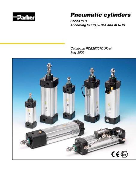
<strong>Pneumatic</strong> <strong>cylinders</strong>Series P1DAccording to ISO, VDMA and AFNORCatalogue PDE2570TCUK-ulMay 2006
P1DCylinderFeatures Air Hydraulic Electrocylinder cylinder mechanicalactuatorsOverload safe *** *** *Easy to limit force *** *** *Easy to vary speed *** *** *Speed *** ** **Reliability *** *** ***Robustness *** *** *Installation cost *** * **Ease of service *** ** *Safety in damp environments *** *** *Safety in explosive atmospheres *** *** *Safety risk with electrical installations *** *** *Risk of oil leak *** * ***Clean, hygienic *** ** *Standardised measurements *** *** *Service life *** *** *Hydraulic system required *** * ***Weight ** ** **Purchase price *** ** *Power density ** *** *Noise level during operation ** *** **High force for size ** *** *Positioning possibilities * *** ***Total energy consumption * ** ***Service interval * ** ***Compressor capacity required * *** **** = good, **=average, ***=excellentImportantBefore attempting any external or internal workon the cylinder or any connected components,make sure the cylinder is vented and disconnectthe air supply in order to ensure isolation of theair supply.NoteAll technical data in this catalogue are typicaldata only.Air quality is essential for maximum <strong>cylinders</strong>ervice life (see ISO 8573).WARNINGFAILURE OR IMPROPER SELECTION OR IMPROPER USE OF THE PRODUCTS AND/OR SYSTEMS DESCRIBED HEREIN OR RELATED ITEMS CAN CAUSE DEATH, PERSONAL INJURY ANDPROPERTY DAMAGE.This document and other information from Parker Hannifin Corporation, its subsidiaries and authorized distributors provide product and/or system options for further investigation by users having technical expertise. It isimportant that you analyze all aspects of your application and review the information concerning the product or system in the current product catalog. Due to the variety of operating conditions and applications for theseproducts or systems, the user, through its own analysis and testing, is solely responsible for making the final selection of the products and systems and assuring that all performance, safety and warning requirements of theapplication are met. The products described herein, including without limitation, product features, specifications, designs, availability and pricing, are subject to change by Parker Hannifin Corporation and its subsidiaries at anytime without notice.SALE CONDITIONSThe items described in this document are available for sale by Parker Hannifin Corporation, its subsidiaries or its authorized distributors. Any sale contract entered into by Parker will be governed by the provisions stated inParker’s standard terms and conditions of sale (copy available upon request).06.05www.parker.com/euro_pneumatic
P1DCylinderContentspageISO cylinder family, P1D .................................................................................4P1D Standard .................................................................................................6P1D Clean ......................................................................................................8P1D Flexible Porting .....................................................................................10P1D Tie-Rod .................................................................................................12Design variants........................................................................................13-16Cylinder forces, double acting variants........................................................17Main data: P1D ............................................................................................17Standard stroke ............................................................................................18Operation data .............................................................................................18Working medium, air quality .........................................................................18Bores and strokes.........................................................................................18Material specification....................................................................................19Cushioning characteristics...........................................................................19Guide for selecting suitable tubing...............................................................20Valve series with respective flows in Nl/minute.............................................21Introduction to the ATEX directive.................................................................22Safety instructions for the P1D-S cylinder with accessories.........................24Dimensions and tolerances.....................................................................26-27Order key P1D Standard and P1D Tie rod ...................................................28Order code standard strokes P1D Standard................................................29Order key for <strong>cylinders</strong> with factory fitted accessories............................30-38Order code standard strokes P1D Clean..................................................3941Order key P1D Flexible Porting.....................................................................42Order code standard strokes P1D Flexible Porting .....................................43Order key P1D Clean and P1D Flexible Porting ...........................................44P1D complete working unit......................................................................45-47P1D cylinder with piston rod locking........................................................48-51P1D with rod guidance modules..............................................................52-55Cylinder mountings..................................................................................56-60Piston rod mountings...............................................................................61-62Combinations...........................................................................................63-64Accessories..................................................................................................65Complete working unit and 3 and 4 position <strong>cylinders</strong>.................................66Sensors ...................................................................................................67-69Connecting cables with one connector........................................................70Connection block Valvetronic 110.................................................................71<strong>Pneumatic</strong> cylinder sensor ......................................................................72-73P1D Seal kits............................................................................................74-75Order key, spare parts..................................................................................76Complete working units – ready for installation.............................................77There is a P1D cylinder for every application .........................................78-79Main order code P1D...............................................................................80-8206.05www.parker.com/euro_pneumatic
P1DCylinderISO cylinder family, P1DA completely new cylinder range from the ground up,with major investment in research, material and technology,demands long experience and major resources.When we developed our P1D cylinder range, we startedfrom scratch, but not really. Decades of research andlearning about what our customers really need worldwidehas given us a very stable foundation to start from.P1D is a cylinder design of the highest possiblequality, every detail has been thought through, withoutmaking any compromises. It has a large number ofinnovations which could only be achieved by using thebest possible materials and methods. The result is acomplete family of ISO/VDMA <strong>cylinders</strong>, of which we arevery proud.P1D is a high technology cylinder design for justabout every conceivable application, both simple andhighly complex.06.05www.parker.com/euro_pneumatic
P1DCylinderThe same high technology platform is used for threemain versions:• P1D Standard – the universal, general purposecylinder with high performance and long life.• P1D Clean – the new product level for ISO/VDMA<strong>cylinders</strong> of clean design with a system of integrated,adjustable sensors (patent applied for), for stringenthygiene demands.• P1D Flexible Porting – the innovative design whichsaves space and reduces dimensions by allowingconnections to be made in the front or rear end of thecylinder.• P1D Tie rod – based on the same high-tech design,the P1D is also available in a tie rod version. Thisfuture-proof cylinder is the perfect choice wherever atie rod cylinder is required.06.05www.parker.com/euro_pneumatic
P1DCylinderThe cylinder end covershave no cavities orpockets which couldcollect water or dirt.This facilitates effectivecleaning.Polyurethane endof-strokewashersgive smooth andquiet operation.The body extrusion isanodised inside andoutside, for long lifeand low friction.All seals are madefrom polyurethane,which gives P1D<strong>cylinders</strong> extra longservice life.The <strong>cylinders</strong> havemagnetic pistonsas standard.Surface treatedsteel end covernuts for toughenvironments.Sealing plugs areavailable for all P1D<strong>cylinders</strong>.The cushioning hasindividual flow geometryfor each <strong>cylinders</strong>ize. This gives effectivecushioning which iseasier to set and adjust.One piston rodnut accordingto ISO 439Bis included asstandard.P1D has a stainless steelpiston rod as standard.Hard chromed steel, hardchromed stainless steeland acid-proof steel areavailable as options.P1D Standard hasa further developmentof our famousbody extrusion withgrooves for the new”drop-in” sensors.All P1D <strong>cylinders</strong> fornormal temperaturehave initial greasing ofa transparent, non-toxicgrease, approved bythe food industry, whichis entirely free fromPTFE and silicone.P1D StandardThe innovative P1D is a future-proof generation ofISO/VDMA <strong>cylinders</strong>. The <strong>cylinders</strong> are double-acting,with a new design of air cushioning. The light, stiff bodyextrusion has sensor grooves for simple and protectedsensor installation.Installation dimensions according to internationalstandardsThe new P1D complies with the current ISO 6431,ISO 15552, VDMA 24562 and AFNOR installation dimensionstandards. For customer reassurance world-wide.High technology designThe best materials, manufacturing methods and designof every detail have been carefully tested, to give thebest possible product. The internal components aremade of high strength plastics, for quiet operationand long service life. The aluminium end caps andthe torsionally stiff aluminium body extrusion make thecylinder robust and suitable for a wide range of applications.High qualityThe P1D has been developed with quality in allphases – requirement specification, design, planning,purchasing, production, distribution and service. Wehave been certified under the ISO 9001 QA standard forthe past ten years. Quality in all our products and servicesis our watchword.Even more functions and variantsThe P1D is available with all the usual optional designs,such as: Through piston rod, high and low temperature,hydraulic operation, extended piston rod etc.A new special variant is the unique self-lubricatingHDPE scraper ring and piston rod seal, speciallydesigned for operation with a completely dry piston rod(i.e. applications where the film of grease on the pistonrod is regularly washed off).06.05www.parker.com/euro_pneumatic
P1DCylinderComplete accessory programmeP1D offers a complete ISO, VDMA and AFNOR compatibleaccessory programme, with a wide range of pistonrod and cylinder mountings for both pivoted and fixedoperation. Several of these types of mountings are availablein stainless steel. The new ”drop-in” sensors areavailable with both reed and electronic operation, with awide choice of connector types and cable lengths.New, mechanically protected sensor technologyThe body extrusion has recessed sensor grooves onthree sides of the cylinder. The new sensors are of the”drop-in” type, and are quickly and easily installed in theT-groove from the side. Both the cable and the sensorare protected in the groove. Choose a sensor with 3 or10 m cable, 8 mm connector or the new M12 connector.Optimised cushioningThanks to the plastic inserts in the end covers, eachcylinder bore has been given individual flow geometry.This provides optimised cushioning, which is quickerand easier to set and adjust.Smooth, quiet operation and long service lifeAll seals and end-of-stroke washers are made from polyurethane(PUR), the bearings and piston are made fromproven engineering plastics with excellent bearing propertiesand all <strong>cylinders</strong> are greased at the factory with atransparent, foodstuffs-approved grease. Altogether thisgives the P1D very long service life and smooth, quietoperation.06.05www.parker.com/euro_pneumatic
P1DCylinderP1D CleanP1D Clean is a new version in our ISO cylinder system,completely designed for the foodstuffs industry. Manyyears’ experience of the stringent requirements forhygiene, choice of material and corrosion resistance,from a wide spectrum of foodstuffs applications haveguided the development of this cylinder version. Greatemphasis has been put on the external design of thecylinder, choice of materials and corrosion protection.Main dimensions according to international standardsAll the main dimensions of the P1D Clean comply withISO 6431, ISO 15552, VDMA 24562 and AFNOR standards.The exception is the somewhat larger footprint ofthe end covers and envelope of the body extrusion, dueto the so-called positive geometry (hygienic, convex,easy-to-clean geometry) of the cushioning adjustmentscrew and the components in the integrated sensorsystem.Common, high technology design platformThe P1D Clean has the same technical platform asthe P1D Standard. The best materials, including thepolyurethane (PUR) seals, manufacturing methods andthe careful attention to detail design give the P1D Cleansmooth, quiet operation and long service life.Convex shape for optimum hygieneP1D Clean has a convex body extrusion, which makesthe <strong>cylinders</strong> easy to keep clean. Irrespective of installationposition, fluids run off the body extrusion surfaces.06.05www.parker.com/euro_pneumatic
P1DCylinderCushioning screw with positive geometryTo offer the best hygiene properties, the projecting cushioningscrew, is sealed with rubber seal against the endcover. This eliminates dirt-collecting cavities and givesthe best hygiene, since it is so easy to clean.Sealing plugsFour plastic sealing plugs are supplied with everyP1D Clean cylinder. These are installed in the end coverscrews which are not used for the cylinder installation. Toensure the sealing function, the plugs can be used onlyonce i.e. they can not be re-used. When installed in theend cover screws, they should be tapped lightly with ahammer to securely fix.Patent applied system for integrated standard sensorsThe P1D Clean cylinder has a system of sensors, whichare fully integrated into the body extrusion, to give the<strong>cylinders</strong> a clean external design. Up to four sensorschosen from the range of P1D standard sensors, reed orelectronic operation, can be mounted in two dedicatedgrooves beneath a transparent, sealed moulding.Tightening the stop screw onto the cam shaft, will lockeach sensor in the desired position, with great force. Thesensor LEDs are always fully visible, which facilitatescommissioning, adjustment and trouble-shooting. Theentire sensor system has a hose-proof design, equivalentto IP65. P1D Clean can be ordered with factoryfittedsensors in the end positions, which can then easilybe moved to any other position along the entire stroke.Up to four integral sensorsCylinders for two integral sensors have two undividedcamshafts along the entire stroke. Free choice of cableexit, front or rear. There is also a version with dividedcamshafts for up to four sensors, which are installed twofrom each end cover, with cable exit front and rear.Simple sensor adjustmentThe sensors are mounted into their groovesthrough the opening in a transparent, sealedcover. The sensor cables have strain reliefand are sealed.The sensor position is easily adjusted byundoing a set screw and using the cable tomove the sensor to the desired position.Once the sensor has been locked in its newposition, the protective cover is installedagain.06.05www.parker.com/euro_pneumatic
P1DCylinderP1D Flexible PortingProgress leads to smaller components and machinery.In harmony with this trend, and complying with the maindimension requirements in ISO 6431, we have developedP1D Flexible Porting, which offers new, smarterdesign solutions. Since one end of the cylinder can beplaced in restricted, unused spaces, without needingany connections, the space in the application can beused more efficiently, or made more compact.Body extrusion with integrated air channelsP1D Flexible Porting has the same body extrusion as theP1D Clean cylinder. Since the air is led through channelsbuilt into the body extrusion, both connections can bemade to either end of the cylinder. The flow capacity ofthe air channels is big enough not to restrict the <strong>cylinders</strong>peed in all normal applications.Main dimensions according to international standardsApart from the projecting connections on sizes Ø32–63mm P1D Flexible Porting complies with ISO 6431, ISO15552, VDMA 24562 and AFNOR standards.Common, high technology design platformP1D Flexible Porting has the same high technologylevel as P1D Standard and P1D Clean. The future-proofdesign gives P1D Flexible Porting high performance andlong service life.1006.05www.parker.com/euro_pneumatic
P1DCylinderStraight or elbow push-in fittings for Ø32-63 mmFor cylinder bore Ø32-63 mm, one connection is locatedon the body extrusion. The connector from the Moduflexvalve range is used for this connection. A matchingPrestolok 2 (plastic) fitting is used for the connectionat the end cover. Choose between straight or elbowfittings. The other end has a plug installed in the unusedcylinder port.Threaded connections for Ø80-125 mmCylinder bore Ø80-125 mm have two threaded connectionslocated in either end cover. The other end hasplugs in the cylinder ports. These plugs can be movedto the other end to suit the application.Mechanically protected ”drop-in” sensorsThe body extrusion, which is common to all P1D Cleanand P1D Flexible Porting <strong>cylinders</strong>, has recessed sensorgrooves in the side opening. The geometry has at thesame time been designed for ”normal” mechanicalsensor installation (similar to P1D Standard) and forthe built-in sensor system (P1D Clean). Use standardsensors in the usual way.Combine with P1D CleanFor compact applications with stringent hygienerequirements, P1D Clean can be combined with FlexiblePorting. This cylinder version complies with manydifferent requirements and offers new opportunities forcreating effective application solutions.1106.05www.parker.com/euro_pneumatic
P1DCylinderP1D Tie-RodThe P1D is available in a tie-rod version, based on thesame high level technology. This future-proof cylinder isthe perfect choice wherever a tie-rod cylinder is needed.Installation dimensions to international standardThe P1D Tie-Rod complies with ISO 6431, ISO 15552,VDMA 24562 and AFNOR installation dimension standards.For customer reassurance world-wide.Smooth, quiet operation and long service lifeAll seals and end-of-stroke washers are made frompolyurethane (PUR), the bearings and piston are madefrom proven engineering plastics with excellent bearingproperties and the initial greasing at the factory with atransparent, foodstuffs-approved grease. Altogether thisgives the P1D very long service life and gentle, quietoperation.Optimised cushioningThanks to the plastic inserts in the end covers, eachcylinder bore has been given an individual flow geometry.This gives an optimised cushioning, which isquicker and easier to set and adjust.Complete accessory programmeP1D offers a complete ISO, VDMA and AFNOR compatibleaccessory programme, with a wide range of pistonrod and cylinder mountings for both pivoted and fixedoperation.”Drop-in” sensorThe P1D Tie-Rod uses ”drop-in” P1D sensors. Aningenious multi-jointed adapter fixes the sensors in anychosen position along the stroke.1206.05www.parker.com/euro_pneumatic
P1DCylinderDesign variants for P1D Standard, P1D Clean, P1D Flexible porting and P1D Tie-RodUsing P1D <strong>cylinders</strong> as a platform, a number of differentdesigns can be produced to suit differing requirements. Pleaserefer to the order key on pages 28 - 51 for the designation ofeach variant.P1D complete working unitP1D Standard can be ordered with a factory-fitted valve andpiping. The valve series is the robust and compact Vikingseries.Of course, the entire range of P1D accessories can also beused for the P1D with built-in valve, and <strong>cylinders</strong> can beordered with factory-fitted accessories and sensors.For more information, see page 45.P1D-LP1D cylinder with piston rod lockingThe P1D cylinder is available in a version with piston rodlocking, allowing the piston rod to be locked in any position.The lock unit, of the air/spring actuated type, is integrated inthe front end piece of the cylinder. The lock unit can be usedfor braking as well as locking. With no signal pressure, the fullforce of the lock is applied to the piston rod, and the lock isreleased at 4 bar signal pressure. Lock units are available forP1D Standard(P1D-L) and P1D Clean (P1D-D) in dimensions Ø32-125 mm.P1D Standard can be ordered with a lock unit and a built-invalve (P1D-4).For more information, see page 48P1D-DP1D cylinder with internal piston rod threadAll P1D <strong>cylinders</strong> are available with an internal piston rodthread where a short installation length is required1306.05www.parker.com/euro_pneumatic
P1DCylinderDesign variants for P1D Standard, P1D Clean, P1D Flexible porting and P1D Tie-RodAlternative piston rod materialsAll P1D <strong>cylinders</strong> in all bores, Ø32-125 mm, can be orderedwith the following piston rod materials:– Steel, hard chromed– Stainless steel, roller polished (standard)– Acid-proof steel, roller polished– Stainless steel, hard chromedThrough piston rodAll P1D <strong>cylinders</strong> in all bores, Ø32-125 mm, are available witha through rod. Cylinders with a through rod can take higherside forces thanks to the double support for the piston rod. Inaddition, this design makes it easier to install external positionsensors.Low and high ambient temperatureFor all bores, Ø32-125 mm, the P1D can be supplied in specialhigh ambient temperature and low ambient temperatureversions. The <strong>cylinders</strong> have seal systems, materials andgrease for their particular temperature ranges. The hightemperature version does not have magnetic piston (no functionat high temperatures). The low temperature <strong>cylinders</strong> dohave magnetic piston, but remember that most sensors arespecified to – 25 °C (no function below this temperature).Ambient temperature ranges:– Low temperature: -40 °C to +40 °C– High temperature: -10 °C to +150 °C, peaks up to +200 °CLow pressure hydraulicsThe P1D in bores Ø32 - 125 mm can be supplied with specialseals for operation with low pressure hydraulics up to 10 bar.Temperature range -20 °C to +80°C.06.0514www.parker.com/euro_pneumatic
P1DCylinderDesign variants for P1D Standard, P1D Clean, P1D Flexible porting and P1D Tie-RodOperation with dry piston rodIn many applications, primarily in the foodstuffs industry, the<strong>cylinders</strong> are cleaned frequently. This means that the film ofgrease on the piston rod is washed off, which puts specialdemands on the materials and the design of the piston rodseal system (scraper ring and piston rod seal). A piston rodseal system specially designed for dry rod operation is availableas options for this type of application, for all bores of P1D<strong>cylinders</strong>. The system has a specially designed L-shapedseal and the material is self-lubricating, high molecular weightplastics (HDPE) – the same system as in our previous P1C<strong>cylinders</strong>, with proven function.P1D with metal scraper ringStandard scraper rings cannot be used in environments wherethe piston rod may be coated with resin, ice, cement, sugarcrystals, dough, etc., primarily in timber handling, refrigerated/chilledtransport, cement industry, chemicals and foodand drinks. Hard and dirty coatings damage the standardscraper rings and shorten their service life, introducing dirtinto the cylinder. A scraper ring has been specially designedfor applications of this kind, as an option for all diameters ofP1D-S, P1D-T and P1D-V <strong>cylinders</strong>. The scraper ring, whichrequires a hard-chromium plated piston rod, has a stainlesssteel carrier, a brass outer scraper ring and a nitrile rubberinner scraper ring.1506.05www.parker.com/euro_pneumatic
P1DCylinderDesign variants for P1D Standard, P1D Clean, P1D Flexible porting and P1D Tie-Rod3 and 4 position <strong>cylinders</strong>By installing two <strong>cylinders</strong> with the same or different stroke, itis possible to build a working unit with three or four positions.This type of unit is available as factory-fitted P1D tie-rod <strong>cylinders</strong>(P1D-T) in all bores, Ø32-125 mm. Other P1D <strong>cylinders</strong>can be flange mounted back-to-back with a special mounting(see pages 59 and 66).Tandem versionThe P1D is also available as a tandem cylinder, i.e. two <strong>cylinders</strong>connected in series. This cylinder unit has almost twicethe force, which is a great advantage in restricted spaces.Tandem <strong>cylinders</strong> are available as tie-rod <strong>cylinders</strong>, P1D-T, inall bores Ø32-125 mm.1606.05www.parker.com/euro_pneumatic
P1DCylinderCylinder forces, double acting variantsCyl. bore/ Stroke Pistonarea Max theoretical force in N (bar)pist. rod mm cm 2 1,0 2,0 3,0 4,0 5,0 6,0 7,0 8,0 9,0 10,032/12 + 8,0 80 161 241 322 402 483 563 643 724 804- 6,9 69 138 207 276 346 415 484 553 622 69140/16 + 12,6 126 251 377 503 628 754 880 1005 1131 1257- 10,6 106 212 318 424 530 636 742 848 954 106050/20 + 19,6 196 393 589 785 982 1178 1374 1571 1767 1963- 16,5 165 330 495 660 825 990 1155 1319 1484 164963/20 + 31,2 312 623 935 1247 1559 1870 2182 2494 2806 3117- 28,0 280 561 841 1121 1402 1682 1962 2242 2523 280380/25 + 50,3 503 1005 1508 2011 2513 3016 3519 4021 4524 5027- 45,4 454 907 1361 1814 2268 2721 3175 3629 4082 4536100/25 + 78,5 785 1571 2356 3142 3927 4712 5498 6283 7069 7854- 73,6 736 1473 2209 2945 3682 4418 5154 5890 6627 7363125/32 + 122,7 1227 2454 3682 4909 6136 7363 8590 9817 11045 12272- 114,7 1147 2294 3440 4587 5734 6881 8027 9174 10321 11468+ = Outward stroke- = Return strokeNote!Select a theoretical force 50-100%larger than the force requiredMain data: P1DCylinder Cylinder Piston rod Cushioning Air con- Connection Flexible Portingdesignation bore area dia. area thread length sump- thread tubing dimensiontion 2)Push-inmm cm 2 mm cm 2 mm litre mmP1D-•032••-XXXX 1) 32 8,0 12 1,1 M10x1,25 17 0,105 G1/8 4 or 6P1D-•040••-XXXX 1) 40 12,6 16 2,0 M12x1,25 19 0,162 G1/4 4 or 6P1D-•050••-XXXX 1) 50 19,6 20 3,1 M16x1,5 20 0,253 G1/4 8 or 10P1D-•063••-XXXX 1) 63 31,2 20 3,1 M16x1,5 23 0,414 G3/8 8 or 10P1D-•080••-XXXX 1) 80 50,3 25 4,9 M20x1,5 23 0,669 G3/8 -P1D-•100••-XXXX 1) 100 78,5 25 4,9 M20x1,5 27 1,043 G1/2 -P1D-•125••-XXXX 1) 125 122,7 32 8,0 M27x2 30 1,662 G1/2Total mass including moving partsCylinder Total mass (kg) Supplement mass (kg) Total mass (kg)designation at 0 mm stroke for rod locking Supplement per 10 mm strokeStandard Tie-Rod Clean/Flex All variants Standard Tie-Rod Clean/FlexP1D-•032••-X 0,55 0,54 0,60 0,31 0,023 0,022 0,047P1D-•040••-X 0,80 0,79 0,88 0,44 0,033 0,030 0,063P1D-•050••-X 1,20 1,20 1,32 0,61 0,048 0,048 0,094P1D-•063••-X 1,73 1,73 1,86 1,25 0,051 0,051 0,101P1D-•080••-X 2,45 2,47 2,63 2,45 0,075 0,079 0,142P1D-•100••-X 4,00 4,00 4,22 3,72 0,084 0,084 0,168P1D-•125••-X 6,87 6,73 7,01 6,07 0,138 0,129 0,248Mass moving parts only (for cushioning calculation)Cylinder Mass moving parts(kg)designation at 0 mm stroke Supplement per 10 mm strokeAll variantsAll variantsP1D-•032••-X 0,13 0,009P1D-•040••-X 0,24 0,016P1D-•050••-X 0,42 0,025P1D-•063••-X 0,50 0,025P1D-•080••-X 0,90 0,039P1D-•100••-X 1,10 0,039P1D-•125••-X 2,34 0,0631) Stroke2) Free air consumption per 10 mm stroke for a double stroke at 6 bar1706.05www.parker.com/euro_pneumatic
P1DCylinderStandard strokeStandard strokes for all P1D <strong>cylinders</strong> comply with ISO 4393. (* 40 is not an ISO standard stroke)Special strokes up to 2800 mm.Minimum stroke for P1D Clean is 25 mm with 0-2 sensors and 100 mm with 3-4 sensors.Order no Cylinder bore = Standard stroke (mm) = Stroke to special orderXXXX = Stroke (mm) 25 40 50 80 100 125 160 200 250 320 400 500 600 700 800 2800Double actingProfile cylinderP1D-S032MS-XXXX 32P1D-S040MS-XXXX 40P1D-S050MS-XXXX 50P1D-S063MS-XXXX 63P1D-S080MS-XXXX 80P1D-S100MS-XXXX 100P1D-S125MS-XXXX 125Operation dataWorking pressureMax 10 barWorking temperature min maxStandard -20 °C +80 °CHigh temp version -10 °C +150 °CLow temp version -40 °C +40 °CBores and strokesP1D32 - 125 mmStandard strokes 25 - 500 mm according to ISO 4393Max stroke2800 mmMin stroke, P1D Clean 25 mm (0-2 sensors)100 mm (3-4 sensors)Greased for life, does not normally need additional lubrication. If extralubrication is given, this must always be continued.Working medium, air qualityWorking mediumDry, filtered compressed airto ISO 8573-1 class 3.4.3.Recommended air quality for <strong>cylinders</strong>For best possible service life and trouble-free operation, ISO 8573-1quality class 3.4.3 should be used. This means 5 µm filter (standardfilter) dew point +3 ºC for indoor operation (a lower dew point shouldbe selected for outdoor operation) and oil concentration 1.0 mg oil/m 3 ,which is what a standard compressor with a standard filter gives.P1D CleanProtection classChemical resistanceHose-proof in accordance with IP65Tested for normally used industrialdetergents, both acid and alkalineISO 8573-1 quality classesQuality Pollution Water Oilclass particle max con- max. press. max consizecentration dew point centration(µm) (mg/m³) (°C) (mg/m³)1 0,1 0,1 -70 0,012 1 1 -40 0,13 5 5 -20 1,04 15 8 +3 5,05 40 10 +7 256 - - +10 -Important!If the cylinder is used in applications withsignificant lateral loads on the piston rod,an external guide must be used to achievemaximum service life. See the examples onpages 52-55.1806.05www.parker.com/euro_pneumatic
P1DMaterial specificationStandard designBody extrusionNatural colour, anodised aluminiumEnd coverBlack anodised aluminiumEnd cover inserts POMEnd cover nuts/screws Zinc plated steel 8.8Piston rod nutZinc plated steelPiston rod Stainless steel, X 10 CrNiS 18 9Scraper ringPURPiston rod bearing POMPistonPOMPiston bearingPOMMagnetic ringPlastic bound magnetic materialPiston boltZinc plated steelPiston sealPURO-ringsNitrile rubber, NBREnd-of-stroke washers PURCushioning seals PURCushioning screws LCPP1D CleanTransparent mouldingTransparent coverScrews, sensor systemUpper seal and lowerseal, protective coverSealing plugsPiston rod nutSiliconeABSStainless steel, A2SantoprenPAStainless steel, A2Cushioning characteristicsThe diagram below is used for dimensioning of <strong>cylinders</strong>related to the cushioning capacity. The maximum cushioningcapacity shown in the diagram assumes the following:• Low load, i.e. low pressure drop across the piston• Equilibrium speed• Correctly adjusted cushioning screw• 6 bar at cylinder portP1D Flexible PortingConnection part Ø32-63Elbow fittings Ø32-63Straight fittings on body extrusion Ø32-63Straight fittings in portsSeal, connection partP1D Tie-RodTie-rods Stainless steel, X 10 CrNiS 18 9CylinderPOMPAPANickel plated brassNitrile rubber NBRDesign variantsLow temperature designSeals/scraper ring Polyurethane PUR/Nitrile rubber NBRPistonAnodised aluminiumPiston/piston rod bearing UHMWPE plasticHigh temperature designSeals/scraper ring Fluorocarbon rubber, FPMPistonAnodised aluminiumPiston/piston rod bearing Bronze filled PTFELow pressure hydraulicsSeals/scraper ring Nitrile rubber, NBRPistonAnodised aluminiumPiston/piston rod bearing UHMWPE plasticCylinders for dry rod operationSeals/scraper ring FPM/HDPECylinder with metal scraper ringScraper ringStainless steel/brass/NBROptionPiston rod materialHard-chromium plated steel, Fe 490-2 FNAcid-proof steel, X 5 CrNiMo 17 13 3Hard-chromium plated stainless steel,X 10 CrNiS 18 9The load is the sum of internal and external friction, plusany gravitational forces. At high relative load (pressure dropexceeding 1 bar), we recommend that for any given speed,the mass should be reduced by a factor of 2.5, or for a givenmass, the speed should be reduced by a factor of 1.5. This isin relation to the maximum performance given in the diagramSpeed [m/s]4,03,02,01,51,0Ø32Ø40Ø50Ø63Ø80Ø1000,50,40,3Ø1250,20,11 2 3 4 5 10 20 30 40 50 100 200 300 500 1000 2000Mass [kg]1906.05www.parker.com/euro_pneumatic
P1DCylinderGuide for selecting suitable tubingThe selection of the correct size of tubing is often based on experience,with no great thought to optimizing energy efficiency andcylinder velocity. This is usually acceptable, but making a roughcalculation can result in worthwhile economic gains.The following is the basic principle:1. The primary line to the working valve could be over sized (thisdoes not cause any extra air consumption and consequentlydoes not create any extra costs in operation).2. The tubes between the valve and the cylinder should,however, be optimized according to the principle that aninsufficient bore throttles the flow and thus limits the <strong>cylinders</strong>peed, while an oversized pipe creates a dead volume whichincreases the air consumption and filling time.The chart below is intended to help when selecting the correctsize of tube to use between the valve and the cylinder.3 Ø12521Ø200Ø160Ø100Ø80Ø63Ø50Ø40Ø32Ø25Ø20Ø16Ø10CylinderØ [mm]1110987654321Equivalent throttling bore 1)The following prerequisites apply:The cylinder load should be about 50% of the theoreticalforce (= normal load). A lower load gives a higher velocityand vice versa. The tube size is selected as a function of thecylinder bore, the desired cylinder velocity and the tube lengthbetween the valve and the cylinder.If you want to use the capacity of the valve to its maximum,and obtain maximum speed, the tubing should be chosen sothat they at least correspond with the equivalent restrictiondiameter (see description below), so that the tubing doesnot restrict the total flow. This means that a short tubing musthave at least the equivalent restriction diameter. If the tubing islonger, choose it from the table below. Straight fittings shouldbe chosen for highest flow rates. (Elbow and banjo fittingscause restriction.)TubeØOut./ØInt.[mm]–/1214/110,2 0,5 0,8 1,1 1,4 0 1 2 3 4 5 6 7 8 9 10Cylinder speed [m/s]4Length of tubing [m]–/16–/15–/14–/1312/1010/88/66/45/34/2,7Air flowQn[Nl/min]40003800360034003200300028002600240022002000180016001400120010008004002001) The “equivalent throttling bore“ is a long throttle (for example a tube) or a series of throttles (for example, through a valve)converted to a short throttle which gives a corresponding flow rate. This should not be confused with the “orifice“ which issometimes specified for valves. The value for the orifice does not normally take account of the fact that the valve contains anumber of throttles.2) Qn is a measure of the valve flow capacity, with flow measured in litre per minute (l/min) at 6 bar(e) supply pressure and 1 barpressure drop across the valve.2006.05www.parker.com/euro_pneumatic
P1DExample 1 : Which tube diameter should be used?A 50 mm bore cylinder is to be operated at 0.5 m/s. Thetube length between the valve and cylinder is 2 m. In thediagram we follow the line from 50 mm bore to 0.5 m/s andget an “equivalent throttling bore“ of approximately 4 mm.We continue out to the right in the chart and intersect the linefor a 2 m tube between the curves for 4 mm (6/4 tube) and 6mm(8/6 tube). This means that a 6/4 tube throttles the velocitysomewhat, while an 8/6 tube is a little too large. We select the8/6 tube to obtain full cylinder velocity.Example 2 : What cylinder velocity will be obtained?A 80 mm bore cylinder will be used, connected by 8 m 12/10tube to a valve with Qn 1200 Nl/min. What cylinder velocity willwe get? We refer to the diagram and follow the line from 8 mmtube length up to the curve for 12/10 tube. From there, we gohorizontally to the curve for the Ø80 cylinder. We find that thevelocity will be about 0.5 m/s.Example 3 : What is the minimum inner diameter andmaximum lenght of tube?For a application a 125 mm bore cylinder will be used.Maximum velocity of piston rod is 0.5 m/s. The cylinder will becontrolled by a valve with Qn 3200 Nl/min. What diameter oftube can be used and what is maximum lenght of tube.We refer to the diagram. We start at the left side of the diagramcylinder Ø125. We follow the line until the intersection with thevelocity line of 0.5 m/s. From here we draw a horizontal line inthe diagram. This line shows us we need an equivalent throttlingbore of approximately 10 mm. Following this line horizontallywe cross a few intersections. These intersections showsus the minimum inner diameter (rightside diagram) in combinationwith the maximum length of tube (bottomside diagram).For example:Intersection one: When a tube (14/11) will be used,the maximum length of tube is 0.7 meter.Intersection two: When a tube (—/13) will be used,the maximum length of tube is 3.7 meter.Intersection three: When a tube (—/14) will be used,the maximum length of tube is 6 meter.CylinderValve series with respective flows in Nl/minuteValve seriesQn in Nl/MinValvetronic Solstar 33Interface PS1 100Valvetronic Interface 2000 100B2 Series 168Adex A05 173Moduflex size 1, (2 x 3/2) 220Valvetronic PVL-B 5/3 closed centre, 6 mm push in 290Moduflex size 1, (4/2) 320B43 Manual and mechanical 340Valvetronic PVL-B 2 x 2/3, 6 mm push in 350Valvetronic PVL-B 5/3 closed centre, G1/8 370Compact Isomax DX02 385Valvetronic PVL-B 2 x 3/2 G1/8 440Valvetronic PVL-B 5/2, 6 mm push in 450Valvetronic PVL-B 5/3 vented centre, 6 mm push in 450Moduflex size 2, (2 x 3/2) 450Flowstar P2V-A 520Valvetronic PVL-B 5/3 vented centre, G1/8 540Valvetronic PVL-B 5/2, G1/8 540Valvetronic PVL-C 2 x 3/2, 8 mm push in 540Adex A12 560Valvetronic PVL-C 2 x 3/2 G1/8 570Compact Isomax DX01 585Valvetronic PVL-C 5/3 closed centre, 8 mm push in 700Valvetronic PVL-C 5/3 vented centre, G1/4 700VIKING P2L-A 760B3 Series 780Valvetronic PVL-C 5/3 closed centre, G1/4 780Moduflex size 2, (4/2) 800Valvetronic PVL-C 5/2, 8 mm push in 840Valvetronic PVL-C 5/3 vented centre, 8 mm push in 840Valvetronic PVL-C 5/2, G1/4 840VIKING P2L-B 1020Flowstar P2V-B 1090ISOMAX DX1 1150B53 Manual and mechanical 1160B4 Series 1170Airline Isolator Valve VE22/23 1470ISOMAX DX2 2330VIKING P2L-D 2880ISOMAX DX3 4050Airline Isolator Valve VE42/43 5520Airline Isolator Valve VE82/83 13680Example 4 : Determining tube size and cylindervelocity with a particular cylinder and valve?For an application using a 40 mm bore cylinder with a valvewith Qn=800 Nl/min. The distance between the cylinder andvalve has been set to 5 m.Tube dimension: What tube bore should be selected to obtainthe maximum cylinder velocity? Start at pipe length 5 m, followthe line up to the intersection with 800 Nl/min. Select the nextlargest tube diameter, in this case Ø10/8 mm.Cylinder velocity: What maximum cylinder velocity will beobtained? Follow the line for 800 Nl/min to the left until it intersectswith the line for the Ø40 mm cylinder. In this example, thespeed is just above 1.1 m/s.2106.05www.parker.com/euro_pneumatic
P1DCylinderLevels of protection for the various equipment categoriesThe various equipment categories must be capable of operatingin accordance with the manufacturer’s operating specifications atdefined levels of protection.Level of Category Type of protection Operating specificationsprotec- Group Grouption I IIVery M1 Two independent means of protection or safety, ensuring that The equipment remains energised andhighthe equipment remains functional even in the event of two faults and functional even with an explosiveoccurring independently of each otheratmosphere presentVery 1 Two independent means of protection or safety, ensuring that The equipment remains energised andhighthe equipment remains functional even in the event of two faults functional in zones 0, 1, 2 (G) and/oroccurring independently of each otherzones 20, 21, 22 (D)High M2 Protection suitable for normal operation and severe The equipment is de-energised in theoperating conditionsevent of an explosive atmosphereHigh 2 Protection suitable for normal operation and frequent faults, or The equipment remains energised and funcequipmentin which faults normally have to be taken into account tional in zones 1, 2 (G) and/or zones 21, 22 (D)Normal 3 Protection suitable for normal operation The equipment remains energised and functionalin zones 2 (G) and/or zones 22 (D)Definition of groups (EN 1127-1)Group I Equipment intended for use in underground parts of mines as well as those parts of surface installations of such mines likely to beendangered by flammable vapours and/or flammable dusts.Group II Equipment intended for use in other places exposed to explosive atmospheres.Group I IImines, combustible vapoursother potentially explosive atmospheres (gases, dust)Category M1 M2 1 2 3Atmosphere* G D G D G DZone 0 20 1 21 2 22G = gas and D = dustTemperature classesClassification of flammable gases and vapours on the basis of ignition temperatureTemperature class Ignition temperature °CT1 Over 450T2 (300) – 450T3 (200) – 300T4 (135) – 200T5 (100) – 135T6 (85) - 100Declaration of conformityThe product catalogues contain copies of the declaration of conformitydemonstrating that the product meets the requirements of directive94/9/EC.The declaration is only valid in conjunction with the instructionscontained in the installation manual relating to the safe use of theproduct throughout its service life.The instructions relating to the conditions in the surrounding area areparticularly important, as the certificate is invalidated if the instructionsare found not to have been adhered to during operation of the product.If there is any doubt as to the validity of the certificate of conformity,contact Parker Hannifin customer service.Operation, installation and maintenanceThe installation manual of the product contains instructions relating tothe safe storage, handling, operation and servicing of the product.The manual is available in different languages, and can bedownloaded from www.parker.com/euro_pneumatic.This document must be made accessible in a suitable place nearwhere the product is installed. It is used as a reference for allpersonnel authorised to work with the product throughout its servicelife.We, the manufacturer, reserve the right to modify, extend or improvethe installation manual in the interests of the users.For more information about ATEX see EUs homepage: http://europa.eu.int/comm/enterprise/atex/2306.05www.parker.com/euro_pneumatic
P1DCylinderSafety instructions for the P1D-S cylinder with accessoriesSupplementary safety instructions for P1D-S<strong>cylinders</strong> installed in Ex-areasSerious, even fatal, damage or injury may be caused by the hotmoving parts of the P1D <strong>cylinders</strong> in the presence of explosivegas mixtures and concentrations of dust.All installation, connection, commissioning, servicing and repair workon P1D <strong>cylinders</strong> must be carried out by qualified personnel takingaccount of the following• These instructions• Markings on the cylinder• All other planning documents, commissioning instructions andconnection diagrams associated with the application.• Provisions and requirements specific to the application• National/international regulations (explosion protection, safety andaccident prevention)Real life applicationsP1D <strong>cylinders</strong> are designed to provide linear movement in industrialapplications, and should only be used in accordance with theinstructions in the technical specifications in the catalogue, and withinthe operating range indicated on the rating plate. The <strong>cylinders</strong> meetthe applicable standards and requirements of directive 94/9/EC (ATEX)The <strong>cylinders</strong> must not be used underground in mines susceptible tofiredamp and/or flammable dusts. The <strong>cylinders</strong> are intended for usein areas in which explosive atmospheres caused by gases, vapoursor mists of flammable liquids, or air/dust mixtures may be expected tooccur during normal use (infrequently)ChecklistBefore using the <strong>cylinders</strong> in an Ex-area, you should check thefollowing:Do the specifications of the P1D-S cylinder match the Ex-classificationof the area of use in accordance with directive 94/9/EC (previouslyATEX 100a)• Equipment group• Ex-equipment category• Ex-zone• Temperature class• Max. surface temperature1. When installing the P1D-S cylinder, is it certain that there is nopotentially explosive atmosphere, oil, acids, gases, vapours orradiation?2. Is the ambient temperature as specified in the technical data in thecatalogue at all times?3. Is it certain that the P1D-S cylinder is adequately ventilated and thatno forbidden additional heat is added?4. Are all the driven mechanical components ATEX certified?5. Check that the P1D-S cylinder is safely earthed.6. Check that the P1D-S cylinder is supplied with compressed air.Explosive gas mixtures must not be used for driving the cylinder.7. Check that the P1D-S cylinder is not equipped with a metal scraperring (special version).Installation requirements in Ex-areas• The temperature of the supply air must not exceed the ambienttemperature.• The P1D-S cylinder may be installed in any position.• An air treatment unit must be attached to the inlet of the P1D-Scylinder.• The P1D-S cylinder must be connected to earth at all times, throughits support, a metallic tube or separate conductor.• The outlet of the P1D-S cylinder must not be open within an Exarea,but must be connected to the silencer or, preferably, pipedand released outside the Ex-area.• The P1D-S cylinder may only drive units that are ATEX certified.• Ensure that the P1D-S cylinder is not exposed to forces greaterthan those permitted in accordance with the catalogue• The P1D-S cylinder must be supplied with compressed air.Explosive gas mixtures must not be used• P1D-S <strong>cylinders</strong> with metal scraper rings must not be used in ExareasInspecting <strong>cylinders</strong> during operationThe P1D cylinder must be kept clean on the outside, and a layer ofdust/dirt thicker than 1 mm must never be allowed to form.Strong solvents should not be used for cleaning, because theycan cause the seal (material PUR) around the piston rod to swell,potentially increasing the temperature. Inspect and verify that thecylinder, with attachments, compressed air fittings, hoses, tubes, etc.meet the standards of ”safe” installation.Marking of cylinder P1D-S Standard(P1D-S***MS-****)II2GDCommunauté Européenne = EUCE on the product shows that Parker Hannifin products meetone or more EU directives.Ex means that this product is intended for use in potentiallyexplosive atmospheres.Stands for the equipment group (I = mines and II = otherhazardous areas).Stands for equipment category 2G means the equipment canbe used in zones 1 and 2 where there is a risk involving gases,vapours or mists of combustible liquids and 2D in zones 21and 22 where there is a risk involving dusts. 2GD Means theequipment can be used in zones 1, 2, 21 and 22.c Safe design (prEN 13463-5)T4II 2GD c T4 120 °CIf equipment is in temperature class T4, the maximum surfacetemperature must not exceed 135 °C. (To guarantee this,the product has been tested to ensure that the maximum is130 °C. This provides a safety margin of 5 °K).120 °C Maximum permitted surface temperature on P1D-S cylinder inatmospheres containing potentially explosive dusts.06.0524www.parker.com/euro_pneumatic
P1DCylinderSupplementary safety instructions for P8S- GPFLX/EX sensors installed in Ex-areasSerious, even fatal, damage or injury may be caused by the hotmoving parts of the P1D <strong>cylinders</strong> in the presence of explosivegas mixtures and concentrations of dust.P8S-GPFLX/EX cylinder sensorII3G EEx nA II T4XII3D 135 °C IP67Instructions for useSafety instructions• Cylinder sensor ATEX classed for category II3G and II3D• Ambient temperature Ta = -20 °C to +45 °C• Temperature class T4, or max. surface temperature of T = 135 °C• Protection class IP67• Read installation instructions before startup• Installation, connection and commissioning must be carried out bytrained personnelApplications• This sensor is designed for use in the T-groove of <strong>cylinders</strong>, anddetects the magnetic field in potentially explosive areas. The sensorcan only be installed in the T-groove of these <strong>cylinders</strong>.• The sensor may also be installed on round <strong>cylinders</strong> by means ofthe following attachments:P8S-TMC01 Suitable for P1S and P1A diameter 10 - 25 mmP8S-TMC02 Suitable for P1S diameter 32 - 63 mmP8S-TMC03 Suitable for P1S diameter 80 - 125 mmThe following data applies to these attachments:- Ambient temperature Ta = 0 °C to 45 °C- Low energy absorption to EN 50 021• The sensor may also be installed on tie-rod <strong>cylinders</strong> or profile<strong>cylinders</strong> by means of this attachment:P8S-TMA0X Suitable for P1D-T diameter 32 - 125 mm, P1E-Tdiameter 160 – 200 mm and C41 diameter 160 – 200 mmInstallationGeneral: The sensor must be protected from UV radiation. The cablemust be installed such that it is protected from external influences, forexample it may be necessary to attach an external strain relief to thecable.Technical data for sensorOperating voltage Ub = 18 to 30 V DCMax. load current Ia d” ¡Ü 70 mAAmbient temperature: -20 °C to 45 °CCommissioningWhen connecting the sensor to a power source, please pay attentionto the followinga) the load data (operating voltage, continuous load current)b) the wiring diagram for the sensorMaintenanceOur P8S-GPFLX/EX cylinder sensor is maintenance free, but the cableconnections should be checked at regular intervals.The sensor must be protected from UV radiation. The sensor must bekept clean on the outside, and a layer of dirt thicker than 1 mm mustnever be allowed to form. Strong solvents should not be used forcleaning as they may damage the sensor.Communatuté Européenne = EUCE on the product shows that Parker Hannifin products meetone or more EU directives.Ex means that this product is intended for use in potentiallyexplosive atmospheres.II Stands for the equipment group (I = mines and II = otherhazardous areas)3G Stands for the equipment category 3G means the equipmentcan be used in zone 2 where there is a risk involving gases,vapours or mists of combustible liquids.EEx EEx means that this is an electrical product intended for use inEx-areas.nA II n Not ignitable to EN50021, A Explosion group tested withacetone, ethanol, toluene and xylene; II Not for use in themining industry.T4 X If equipment is in temperature class T4, the maximum surfacetemperature must not exceed 135 °C. (To guarantee this,the product has been tested to ensure that the maximum is130 °C. This provides a safety margin of 5 °K.) X Must beinstalled in accordance with the installation manual.3D Stands for equipment category 3D in zone 22 where there is arisk involving dusts.135 °C Maximum permitted surface temperature on the sensor inatmospheres containing potentially explosive dusts.IP67 Satisfies protection class IP67.Components such as cylinder attachments, tubefittings, tubes, etc.ComponentsParker Hannifin guarantees that our cylinder attachments, tube fittings,tubes, etc. are not subject to the provisions of the ATEX directive.A component means any item essential to the safe functioning ofequipment and protective systems but with no autonomous function.Components intended for incorporation into equipment or protectivesystems which are accompanied by an attestation of conformitywith the ATEX directive, including a statement of their characteristicsand how they must be incorporated into products, are consideredto conform to the applicable provisions of directive 94/9/EC. Excomponentsas defined in the European standard EN 50014 arecomponents in the sense of the ATEX directive 94/9/EC as well.Components must not have the CE marking affixed unless otherwiserequired by other directives.Examples of components:• terminals• push buttons assemblies• relays• empty flameproof enclosures• ballasts for fluorescent lamps• meters (e.g. moving coil)• encapsulated relays and contactors, with terminals and/or flyingleads2506.05www.parker.com/euro_pneumatic
P1DStandard cylinderP1D StandardCAD drawings on the InternetOur home page www.parker.com/euro_pneumatic includes the AirCadDrawingBGAML12EEPPPLRTOASSØBØDKKØD 4TTØBADIN 439BSWInternal piston rod threadWLVDL2WHGL8 + SGVAREWTL9 + 2 x SWHWH + SWHDimensionsCylinder bore AM B BA BG D D4 E EE G KK L2 L8 L9 L12mm mm mm mm mm mm mm mm mm mm mm mm mm mm32 22 30 30 16 12 45,0 50,0 G1/8 28,5 M10x1,25 16,0 94 146 6,040 24 35 35 16 16 52,0 57,4 G1/4 33,0 M12x1,25 19,0 105 165 6,550 32 40 40 16 20 60,7 69,4 G1/4 33,5 M16x1,5 24,0 106 180 8,063 32 45 45 16 20 71,5 82,4 G3/8 39,5 M16x1,5 24,0 121 195 8,080 40 45 45 17 25 86,7 99,4 G3/8 39,5 M20x1,5 30,0 128 220 10,0100 40 55 55 17 25 106,7 116,0 G1/2 44,5 M20x1,5 32,4 138 240 14,0125 54 60 60 20 32 134,0 139,0 G1/2 51,0 M27x2 45,0 160 290 18,0Cylinder bore OA PL PP R RT SS SW TT VA VD WH WL WTmm mm mm mm mm mm mm mm mm mm mm mm32 6,0 13,0 21,8 32,5 M6 4,0 10 4,5 3,5 4,5 26 21 M8x140 6,0 14,0 21,9 38,0 M6 8,0 13 5,5 3,5 4,5 30 23 M10x1,2550 8,0 14,0 23,0 46,5 M8 4,0 17 7,5 3,5 5,0 37 31 M14x1,563 8,0 16,4 27,4 56,5 M8 6,5 17 11,0 3,5 5,0 37 31 M14x1,580 6,0 16,0 30,5 72,0 M10 0 22 15,0 3,5 4,0 46 39 M18x1,5100 6,0 18,0 35,8 89,0 M10 0 22 20,0 3,5 4,0 51 39 M18x1,5125 8,0 28,0 40,5 110,0 M12 0 27 17,5 5,5 6,0 65 53 M24x2S=StrokeTolerancesCylinder bore B BA L 8L 9R Stroke tolerance Stroke tolerancemm mm mm mm up to stroke 500 mm for stroke over 500 mm32 d11 d11 ±0,4 ±2 ±0,5 +0,3/+2,0 +0,3/+3,040 d11 d11 ±0,7 ±2 ±0,5 +0,3/+2,0 +0,3/+3,050 d11 d11 ±0,7 ±2 ±0,6 +0,3/+2,0 +0,3/+3,063 d11 d11 ±0,8 ±2 ±0,7 +0,3/+2,0 +0,3/+3,080 d11 d11 ±0,8 ±3 ±0,7 +0,3/+2,0 +0,3/+3,0100 d11 d11 ±1,0 ±3 ±0,7 +0,3/+2,0 +0,3/+3,0125 d11 d11 ±1,0 ±3 ±1,1 +0,3/+2,0 +0,3/+3,006.0526www.parker.com/euro_pneumatic
P1DClean/Tie-Rod/Flexible PortingP1D CleanAMMinimum stroke for P1D Clean is 25 mm with 0-2 sensors and 100 mm with 3-4 sensors.PPL12EEPLRTE2 maxOAØBØDKKØD 7TTØBASSDIN 439BSWVDL2WHGL 8 + SGVAREE1P1D Tie-RodAML12EEPPPLRTOAØBØDKKØD6ØD5TTØBASSDIN 439BSWVDL2WHGL 8 + SGVAREP1D Flexible PortingAML12EEPPPLRTE3OAØBØDKKØD 7TTØBASSDIN 439BSWDimensionsVDL2WHGL 8 + SCylinder bore Elbow fittings, tubing Ømm Straight fittings, tubing Ømm4 6 8 10 4 6 8 10D5 D6 D7 E1 E2max E3 E3 E3 E3 E3 E3 E3 E3mm mm mm mm mm mm mm mm mm mm mm mm mm mm32 36 5,3 49,6 32 30,0 42 44 - - 38 40 - -40 44 5,3 57,3 36 34,7 46 48 - - 42 44 - -50 55 7,1 69,3 42 40,7 - - 56 76 - - 48 5063 68 7,1 82,3 49 46,2 - - 64 83 - - 55 7580 86 8,9 99,3 57 54,7 - - - - - - - -100 106 8,9 117,6 68 64,0 - - - - - - - -125 132 10,8 142,8 81 75,5 - - - - - - - -Other dimensions, see opposite pageP1D Flexible Porting Ø80 - Ø125 can be ordered with threaded ports only or with factory-fitted elbow or straight push-in fittings(see position 20 in the order code key page 32)GVARE2706.05www.parker.com/euro_pneumatic
P1DThe simple and complete order keyThe P1D order key is based on the same principles as itspredecessors, the P1C and P1E. This makes it easy to identifyand order all common cylinder versions. The change-over fromour previous cylinder ranges to the equivalent P1D <strong>cylinders</strong> islogical and simple. As far as possible, the same symbols as forP1C and P1E have been retained for the same functions. Mostof the common cylinder types in the P1D-family have a 15-digitorder number.P1D Standard and P1D Tie rodAll common P1D <strong>cylinders</strong> have the same order number as theirpredecessors, P1C and P1E, but with the C or E replaced by D.CylinderMany of our new cylinder versions, e.g. P1D Clean and P1DFlexible Porting, and complete working units (with factoryfittedcylinder mountings, sensors etc.) are defined by a20-digit order number. There is only one single order key forP1D, which thus contains the 15-digit order numbers for themost common cylinder types and 20-digit order numbers for<strong>cylinders</strong> with more functions. Remember that there are always15 or 20 positions in the order number – never any figure inbetween.II 2GD c T4 120 °CValid for P1D-S***MS-****, see ATEX information pages 22 - 25.1 2 3 4 5 6 7 8 9 10 11 12 13 14 15P 1 D – S 0 3 2 M S – 0 1 0 0Cylinder versionS StandardC Clean 2)F Flexible PortingT Tie-RodStroke (mm)e.g. 0100 = 100 mmOptional stroke lengthsup to 2800 mm. Standardstrokes see table page 18Piston rodmaterialSealsCylinder boremm032040050063080100125End cover screwsStandard Stainlesssteel 22)Std scraperMetalavskrapare 25)HDPE scraper 23)FPM sscraperStd scraperMetalavskrapare 25)HDPE scraper 23)FPM sscraperFunctionM Q D V A S H W Double-actingF R E B G T YZ Double-actingthrough rod2 4 6 8 – – – – 3 and 4 position <strong>cylinders</strong>C J K L – – – – TandemStainless steelChromium-plated steelAcid-proof steelChrom.-pl. stainless steelS C M R Standard -20 °C to +80 °C.F G N D High temperature version 6)-10 °C to +150 °C.No magnetic functionL K P E Low temperature version 6)-40 °C to +40 °C.6) 24)– J – Z Low pressure hydraulic2) P1D Clean without sensor function, see page 41.6) For P1D-S and P1D-T.22) If stainless steel end cover screws are selected, the piston rod nuts are also supplied in stainless steel.23) For dry rod operation.24) The seal system for low pressure hydraulics demands a hard chromed surface for proper function.25) The metal scraper ring requires a hard-chromium plated piston rodExample 1 Standard, double acting cylinderStandard cylinder with standard scraper ring (PUR), standard pistonrod material (stainless steel) and standard temperature range.Example 2 Tie-Rod design, double acting cylinderTie-rod cylinder with standard scraper ring (PUR), hard chromed steelpiston rod and standard temperature range.P1DP1D-S032MS-0160P1D-S100MS-0400Compare P1C and P1EP1C-S032MS-0160P1E-S032MS-0160P1C-S100MS-0400P1E-S100MS-0400P1DP1D-T040MC-0125Compare P1EP1E-T040MC-012506.0528www.parker.com/euro_pneumatic
P1DCylinderP1D StandardThe order numbers on this page refer to P1D Standard withoutsensors. The <strong>cylinders</strong> can be ordered with sensors, fittings,piston rod and cylinder mountings, speed controls etc. for efficientlogistics. Please refer to the order key to select <strong>cylinders</strong>with factory-fitted accessories.II 2GD c T4 120 °CSee ATEX information pages 22 - 25.P1D StandardDouble-actingCyl. bore Stroke Order codemmmm32 25 P1D-S032MS-002540 P1D-S032MS-004050 P1D-S032MS-005080 P1D-S032MS-0080100 P1D-S032MS-0100125 P1D-S032MS-0125160 P1D-S032MS-0160200 P1D-S032MS-0200250 P1D-S032MS-0250320 P1D-S032MS-0320400 P1D-S032MS-0400Conn. G1/8 500 P1D-S032MS-050040 25 P1D-S040MS-002540 P1D-S040MS-004050 P1D-S040MS-005080 P1D-S040MS-0080100 P1D-S040MS-0100125 P1D-S040MS-0125160 P1D-S040MS-0160200 P1D-S040MS-0200250 P1D-S040MS-0250320 P1D-S040MS-0320400 P1D-S040MS-0400Conn. G1/4 500 P1D-S040MS-050050 25 P1D-S050MS-002540 P1D-S050MS-004050 P1D-S050MS-005080 P1D-S050MS-0080100 P1D-S050MS-0100125 P1D-S050MS-0125160 P1D-S050MS-0160200 P1D-S050MS-0200250 P1D-S050MS-0250320 P1D-S050MS-0320400 P1D-S050MS-0400Conn. G1/4 500 P1D-S050MS-050063 25 P1D-S063MS-002540 P1D-S063MS-004050 P1D-S063MS-005080 P1D-S063MS-0080100 P1D-S063MS-0100125 P1D-S063MS-0125160 P1D-S063MS-0160200 P1D-S063MS-0200250 P1D-S063MS-0250320 P1D-S063MS-0320400 P1D-S063MS-0400Conn. G3/8 500 P1D-S063MS-0500P1D StandardDouble-actingCyl. bore Stroke Order codemmmm80 25 P1D-S080MS-002540 P1D-S080MS-004050 P1D-S080MS-005080 P1D-S080MS-0080100 P1D-S080MS-0100125 P1D-S080MS-0125160 P1D-S080MS-0160200 P1D-S080MS-0200250 P1D-S080MS-0250320 P1D-S080MS-0320400 P1D-S080MS-0400Conn. G3/8 500 P1D-S080MS-0500100 25 P1D-S100MS-002540 P1D-S100MS-004050 P1D-S100MS-005080 P1D-S100MS-0080100 P1D-S100MS-0100125 P1D-S100MS-0125160 P1D-S100MS-0160200 P1D-S100MS-0200250 P1D-S100MS-0250320 P1D-S100MS-0320400 P1D-S100MS-0400Conn. G1/2 500 P1D-S100MS-0500125 25 P1D-S125MS-002540 P1D-S125MS-004050 P1D-S125MS-005080 P1D-S125MS-0080100 P1D-S125MS-0100125 P1D-S125MS-0125160 P1D-S125MS-0160200 P1D-S125MS-0200250 P1D-S125MS-0250320 P1D-S125MS-0320400 P1D-S125MS-0400Conn. G1/2 500 P1D-S125MS-0500The <strong>cylinders</strong> are supplied complete with one zinc plated steel pistonrod nut.06.0529www.parker.com/euro_pneumatic
P1DCylinderP1D <strong>cylinders</strong> with piston rod mountings and end cover screw sealing plugsUsing the 20-digit order number, it is possible to ordercomplete working units with factory installed piston rods andcylinder mountings, sensors etc.Piston rod mountings and sealing plugs for the cylinder endcover screws are specified in position 16 in accordance withthe order key below.Please note that an order code with sealing plugs must becombined with selecting a cylinder mounting in position 17.The sealing plugs are installed in the end cover screws whichare not used.1 2 3 4 5 6 7 8 9 10 11 12 13 14 15 16 17 18 19 20P 1 D – S 0 4 0 M S – 0 3 2 0 C N N N NFactory-fitted piston rod mountings and sealing plugsNo plugsWith plugs 8)S A Swivel rod eye, zinc-plated steelT 1 Swivel rod eye, stainless steel 10)V E Swivel rod eye, zinc-plated steel and clevis bracket GAW 2 Swivel rod eye, stainless steel and clevis bracket GA 10)C B Clevis, zinc-plated steelD 3 Clevis, stainless steel 10)F G Flexo coupling, zinc-plated steelX P One additional piston rod nut 9)Y 4 Piston rod nut in stainless steel 10)Z 5 Piston rod nut in acid-proof steel6 7 Without piston rod nutH L Rod guidance module, H style, ball bearings 18)J M Rod guidance module, H style, plain bearings 18)K Q Rod guidance module, U style, plain bearings 18)N R None8) Valid only for <strong>cylinders</strong> with factory-fitted cylinder mountings. P1D Clean <strong>cylinders</strong> are always delivered with 4 sealing plugs.9) P1D <strong>cylinders</strong> are always delivered with one piston rod nut in zinc-plated steel, except P1D Clean which is delivered with the piston rod nutin stainless steel. Codes X and P mean that the cylinder is delivered with one additional nut of the same type.10) The piston rod nut in zinc-plated steel is replaced by a nut in stainless steel(P1D Clean is always delivered with one piston rod nut in stainless steel).18) Only for bore 32-100 mmExample of piston rod fittings and end cover screw sealing plugsP1D-S040MS-0320CNNNN P1D Standard with a zinc plated clevis on the piston rod and without sealing plugs in the end cover screwsP1D-S080MS-0250ATNNN P1D Standard with swivel rod eye on the piston rod, clevis bracket MP2 installed on rear end cover andsealing plugs in the cylinder end cover screws in the front end.06.0530www.parker.com/euro_pneumatic
P1DCylinderP1D <strong>cylinders</strong> with centre trunnion and cylinder mountingsThere are three different types of centre trunnion in the P1Dfamily. A centre trunnion for the P1D Standard and one for theP1D Tie-Rod placed in the centre or an optional location of thecylinder, or a flange mounted centre trunnion on the front orrear end cover that fits all P1D <strong>cylinders</strong>.For the P1D, the centre trunnion is available among thecylinder mountings in position 17. If G or 7 appears in position17, the position of the centre trunnion should be specified asa three-digit measurement in positions 18-20. For P1D-S, 000indicates a loose centre trunnion. If D or 6 appears in position17, the centre trunnion is always centred on the cylinder (nomeasurement specified in positions 18-20). For some of ourprevious cylinder series, the centre trunnion is selected back inposition 5, e.g. P1C-C. Remember that C in position 5 for P1Dmeans the Clean cylinder version and nothing else!It is possible to equip the <strong>cylinders</strong> with factory installedpiston rod mountings, sensors, fittings etc. in the usual way.For the version with optional location of the centre trunnion orloose centre trunnion, no choices can be made for positions18-20 since they are used for the XV dimension. (See page 60)1 2 3 4 5 6 7 8 9 10 11 12 13 14 15 16 17 18 19 20P 1 D – T 0 4 0 M S – 0 3 2 0 N D N N NCylinder versionS StandardC Clean 2)F Flexible PortingT Tie-RodCylinder mountings90° 0° 90° = shaft square to, 0° = shaft in line with ports 5)1 3 Flange MF1/MF2 in front endB 4 Flange MF1/MF2 in rear end2 K Flange MF1/MF2 in both endsF – Foot brackets MS1 (both ends)C U Clevis bracket GAE V Clevis bracket MP4S W Swivel eye bracketT Y Clevis bracket MP2L Z Clevis bracket MP2+MP4X 5 Clevis bracket MP2+pivot bracket with rigid bearingQ 0 Clevis bracket GA + pivot bracket with swivel bearingM A Clevis bracket GA +swivel eye bracketD 6 Centre trunnion MT4, mid position 6)G 7 Trunnion MT4, optional pos. (XV-meas. pos 18-20) 7)H P Trunnion flange in front endJ 8 Trunnion flange in rear endN None2) P1D Clean without sensor function, see page 41.5) Shaft or pivots square to or in line with the cylinder ports.6) For versions P1D-S and P1D-T7) For P1D-S and P1D-T, XV-measure (from the piston rod thread according to ISO to the centre of the pivots) stated in mm in positions 18-20(max 999, or 000 if loose centre trunnion specified). For XV measures, see page 60.Examples of centre trunnionP1D-S050MS-0250NDNNN P1D Standard rod cylinder with centre trunnion installed in centre of cylinder.P1D-T050MS-0250NG205 P1D Tie rod cylinder with centre trunnion installed on XV dimension specified in positions 18,19 and 20.P1D-S032MS-0160NHNNN P1D Standard cylinder with trunnion flange mounted on front end cover.P1D-S032MS-0160NJNNN P1D Standard cylinder with trunnion flange mounted on rear end cover.Examples of other combinationsP1D-C050MS-02501HQN6P1D-F080MSJ0400XJFN0P1D Clean cylinder with trunnion flange mounted on front end cover, two reed sensors, 8 mm connector(1 m cable), cable connection on rear end cover, factory installed stainless steel swivel rod eye, push-infittings (Prestolok, nickel plated brass) low elbow type for 6 mm tube, sealing plugs installed in unused endcover screws (code 1 for stainless swivel rod eye).P1D Flexible Porting cylinder with trunnion flange mounted on rear end cover, two threaded connections inrear end cover, extra zinc plated steel piston rod nut (i.e. a total of two zinc plated steel nuts), two factoryinstalled electronic sensors, 24 VDC, PNP type, 3 m cable, factory installed push-in fittings (Prestolok,nickel plated brass) low elbow type for 10 mm tube.3106.05www.parker.com/euro_pneumatic
P1DCylinderFactory-fitted sensorsAll P1D <strong>cylinders</strong> can be supplied with up to four factoryinstalled sensors (standard reed or electronic sensors) inspecially designed grooves. Both cable and sensor areprotected in the groove. Choose a sensor with 3 or 10 m cableor with 8 mm connector.P1D Clean has a system of sensors fully integrated in thebody extrusion, in specially designed grooves underneath atransparent, sealed moulding. The factory installed sensors areinstalled at the end positions and can then easily be movedanywhere along the entire stroke during commissioning. Thesensors can be ordered with cable exit in the front end cover,rear end cover or at both end covers.For <strong>cylinders</strong> with 3 sensors, 2 sensors are installed in therear end position and one sensor in the front end position.Cylinders with 4 sensors are supplied with 2 sensors in eachend position.1 2 3 4 5 6 7 8 9 10 11 12 13 14 15 16 17 18 19 20P 1 D – S 0 5 0 M S – 0 3 2 0 N N C N NFactory-fitted sensorsFront end or left 11)Rear end or right 11)Front and rear endCable exitF R – 2 sensors 24 VDC pnp, 3 m cableG H – 2 sensors 24 VDC pnp, 10 m cableC S – 2 sensors 24 VDC pnp, 8 mm connector 21)K L – 2 sensors Reed type, 3 m cableT V – 2 sensors Reed type, 10 m cableM Q – 2 sensors Reed type, 8 mm connector 21)– – 3 3 sensors 24 VDC pnp, 8 mm connector 21)– – Z 3 sensors Reed type, 8 mm connector 21)– – 4 4 sensors 24 VDC pnp, 8 mm connector 21)– – W 4 sensors Reed type, 8 mm connector 21)6 12) 7 13) 8 14) No factory-fitted sensors P1D CleanNNo sensors P1D (excl. P1D Clean)11) Left and right valid for P1D Standard and P1D Tie-Rod seen from behind with the ports on top.The sensors can only be mounted on the left for P1D Flexible Porting.12) No factory-fitted sensors, but prepared for cable exit in the front end (max. 2 sensors).13) No factory-fitted sensors, but prepared for cable exit in the rear end (max. 2 sensors).14) No factory-fitted sensors, but prepared for cable exit in both ends (max. 4 sensors).21) The standard cable length is 0.27 m. However, P1D Clean is supplied with 1 m cable length.Depending on the location of the sensors, the cable length (1 m) may limit the stroke of the P1D Clean cylinderExample of sensorsP1D-S050MS-0320NNCNN P1D Standard with two factory installed sensors 24 VDC PNP, 8 mm connectorP1D-C063MS-0250NNLNN P1D Clean with two factory installed Reed sensors, 3 m cable and cable connection at rear end cover on left sideP1D-F080MS-0400NNMNN P1D Flexible Porting with two factory installed Reed sensors, 8 mm connector06.0532www.parker.com/euro_pneumatic
P1DCylinderPre-assembled fittings or speed controlsAll P1D <strong>cylinders</strong> can be delivered with elbow or straight pushinfittings in nickel-plated brass (Prestolok) or speed controlsin brass (series PTF). P1D Clean <strong>cylinders</strong> are factory-fittednickel-plated versions of the PTF speed controls. Please seepage 42 for the order code key for P1D Flexible Porting withpre-assembled fittings.1 2 3 4 5 6 7 8 9 10 11 12 13 14 15 16 17 18 19 20P 1 D – S 0 5 0 M S – 0 3 2 0 N N N N 8Speed controls orfittings for tube dimensionSpeed controls 17)Series PTF 4PB 16)X in both ends for tube 4 mmY in both ends for tube 6 mmZ in both ends for tube 8 mmP in both ends for tube 10 mmR in both ends for tube 12 mmPush-in fitting, elbow type for:4 Tube dimension 4 mm6 Tube dimension 6 mm8 Tube dimension 8 mm0 Tube dimension 10 mm2 Tube dimension 12 mmPush-in fitting, straight type for:1 Tube dimension 4 mmAvailable fittings and speed controls for P1D StandardCyl. Speed controls Elbow fitting Straight fittingbore for tube for tube for tube32 4, 6, 8 4, 6, 8 4, 6, 840, 50 6, 8 4, 6, 8, 10, 12 4, 6, 8, 10, 1263, 80 8, 10, 12 8, 10, 12 8, 10, 12100, 125 12 12 10, 123 Tube dimension 6 mm5 Tube dimension 8 mm7 Tube dimension 10 mm9 Tube dimension 12 mmN None16) P1D Clean <strong>cylinders</strong> have factory fitted nickelplated versions of the PTF series.17) Not available for P1D Flexible Portingbore 32-63 mm.Example P1D Standard with factory-fitted fittings or speed controlsP1D-S050MS-0320NNNN8 P1D Standard cylinder with two push-in fittings, elbow type for 8 mm tube.P1D-S125MS-0400NNNNR P1D Standard cylinder with two speed controls for 12 mm tube.06.0533www.parker.com/euro_pneumatic
P1DCylinderExtended piston rodAll <strong>cylinders</strong> in the P1D family can be ordered with extendedpiston rod, for all piston rod materials. To make it possible tocombine piston rod extension with all the functions and propertiesin the P1D system, the three positions which normally1 2 3 4 5 6 7 8 9 10 11 12 13 14 15P 1 D – S K R 5 M S – 0 3 2 0specify cylinder bore are used to specify both bore and extension.When ordering a P1D cylinder with extended piston rod,specify this as below.Cylinderbore mmK 32L 40M 50N 63P 80Q 100R 125Piston rod extensionE.g. KR5 = Cylinder bore 32 mmwith piston rod extension = 255 mm01-99 1-99 N0-N9 220-229A0-A9 100-109 P0-P9 230-239B0-B9 110-119 Q0-Q9 240-249C0-C9 120-129 R0-R9 250-259D0-D9 130-139 S0-S9 260-269E0-E9 140-149 T0-T9 270-279F0-F9 150-159 U0-U9 280-289G0-G9 160-169 V0-V9 290-299H0-H9 170-179 W0-W9 300-309J0-J9 180-189 X0-X9 310-319K0-K9 190-199 Y0-Y9 320-329L0-L9 200-209 Z0-Z9 330-339M0-M9 210-219The maximum extended piston rod length that canbe specified by the order key is 339 mm. If a longerextended piston rod is needed please contact usand we will organise a special part number.By changing from 032 to KR5, the cylinder hasbeen given a 255 mm extended piston rod. At thesame time, the cylinder can be specified with allfunctions and properties in the other positions.Example of an extended piston rodP1D-SK45MS-0200 P1D Standard cylinder, bore 32 mm, with a 45 mm extended piston rod.P1D-TPD2MS-0500 P1D Tie-Rod cylinder, bore 80 mm, with 132 mm extended piston rod.Piston rod in alternative materialsP1D has a polished stainless steel piston rod as standard. Ifyou want a different material and/or surface treatment, pleaseorder this in combination with seal material in position 10.Piston rod nuts are supplied in zinc plated steel as standard,but stainless steel piston rod nuts are always supplied forP1D Clean. If an alternative material is used, the piston rod nutis always supplied in the same material.1 2 3 4 5 6 7 8 9 10 11 12 13 14 15P 1 D – S 0 3 2 M S – 0 1 0 0Piston rodmaterialSealsStainless steelChromium-plated steelAcid-proof steelChrom.-pl. stainless steelS C M R Standard -20 °C to +80 °C.F G N D High temperature version 6)-10 °C to +150 °C. No magnetic functionL K P E Low temperature version -40 °C to +40 °C. 6)6) 24)– J – Z Low pressure hydraulic6) For P1D-S and P1D-T.24) The seal system for lowpressure hydraulicsdemands a hard chromedsurface for proper function.Example of piston rod materialP1D-S032MS-0100P1D Standard cylinder, bore 32 mm, with stainless steel piston rod (standard)P1D-T040MC-0160P1D Tie-Rod cylinder, bore 40 mm, with hard chromed steel piston rod3406.05www.parker.com/euro_pneumatic
P1DCylinderHigh and low temperature and low pressure hydraulicsThe new P1D system contains cylinder versions for high andlow temperature and low pressure hydraulics. These versionshave material and sealing systems specially designed for theirparticular temperature ranges. End covers and pistons aremade entirely from metal, to give optimum function at high orlow temperature in combination with seals made from speciallytested materials and special grease. These variants are availablewith the P1D-S and P1D-T models. The low temperatureversion has a magnetic ring in the piston for proximity sensing(but please note that the sensors are normally specified for fullperformance down to –25 °C only), whereas the high temperatureversion does not have a magnetic ring in the piston.The high temperature version is chosen by the letter F in posi-tion 10 (or G, D, N for other piston rod materials, see the table).The low temperature version is chosen by the letter L in position10 (or K, E, P for other piston rod materials, see the table).Order <strong>cylinders</strong> for low pressure hydraulics by specifying theletter J (hard chromed steel piston rod) or Z (hard chromedstainless steel piston rod) in position 10 in the table below.Please note that this version requires a piston rod with hardchromed surface.Certain restrictions apply to choosing sensors, piston rodmountings, cylinder mountings and fittings due to the temperaturerange. However, the high temperature <strong>cylinders</strong> can notbe supplied with sensors, i.e. always code N inposition 18.1 2 3 4 5 6 7 8 9 10 11 12 13 14 15P 1 D – S 0 6 3 M F – 0 3 2 0Cylinder versionS StandardC CleanF Flexible PortingT Tie-RodPiston rodmaterialStainless steelChromium-plated steelAcid-proof steelChrom.-pl. stainless steelSealsS C M R Standard -20 °C to +80 °C.F G N D High temperature version 6)-10 °C to +150 °C.No magnetic function.L K P E Low temperature version 6)-40 °C to +40 °C.24) 24)– J – Z Low pressure hydraulic6) For P1D-S and P1D-T.24) The seal system for low pressure hydraulics demands a hard chromed surface for proper function.Examples of high and low temperature, and low pressure hydraulicsP1D-S032MF-0125 P1D cylinder, version S, high temperature design, no magnetic function.P1D-S050ML-0250 P1D cylinder, version S, low temperature design, built-in magnetic ring (but the sensors havenormally acceptable function to –25 °C only).P1D-S063MF-0320S1NNN P1D cylinder, version S, high temperature design, no magnetic function, zinc plated steel swivel rod eye,flange on front end cover.P1D-S050MJ-0200 P1D cylinder, version S, low pressure hydraulic version, hard chromed piston rod, magnetic ring built in.3506.05www.parker.com/euro_pneumatic
P1DCylinderThrough piston rodAll P1D <strong>cylinders</strong> can be ordered with a through piston rod.Order this design in position 9 in combination with the scraperring system as below.1 2 3 4 5 6 7 8 9 10 11 12 13 14 15P 1 D – S 0 3 2 F S – 0 1 0 0End cover screwsStandard Stainlesssteel 22)Std scraperMetalavskrapare 25)HDPE scraper 23)FPM sscraperStd scraperMetalavskrapare 25)HDPE scraper 23)FPM sscraperFunction22) If stainless steel end cover screwsare selected, the piston rod nuts arealso supplied in stainless steel.23) For dry rod operation.25) The metal scraper ring requires ahard-chromium plated piston rodM Q D V A S H W Double-actingF R E B G T YZ Double-actingthrough rodExample of through piston rodP1D-S032FS-0100P1D Standard cylinder, bore 32 mm, with through piston rodP1D-T050FS-0125P1D Tie-Rod cylinder, bore 50 mm, with through piston rod3 and 4 position <strong>cylinders</strong>Factory-fitted 3 and 4 position <strong>cylinders</strong> can be ordered in tie-rod design P1D-T.Through going tie-rods fix the two <strong>cylinders</strong> into a compact unit.1 2 3 4 5 6 7 8 9 10 11 12 13 14 15 16 17 18 19 20P 1 D – T 0 8 0 2 S – 0 2 0 0 N 0 2 5 0Cylinder versionS StandardC CleanF Flexible PortingT Tie-RodEnd cover screwsStandard Stainlesssteel 22)Std scraperMetalavskrapare 25)HDPE scraper 23)FPM sscraperStd scraperMetalavskrapare 25)HDPE scraper 23)FPM sscraperFunctionM Q D V A S H W Double-actingF R E B G T YZ Double-actingthrough rod2 4 6 8 – – – – 3 and 4 position <strong>cylinders</strong>C J K L – – – – Tandem22) If stainless steel end cover screwsare selected, the piston rod nuts arealso supplied in stainless steel.23) For dry rod operation.25) The metal scraper ring requires ahard-chromium plated piston rodEqual stroke – 3 position cylinderSpecify letter T in position 5 (P1D-T) and figure 2 in position 9(standard scraper ring)Unequal stroke – 4 position cylinderSpecify letter T in position 5 (P1D-T) and figure 2 in position 9(standard scraper ring)Specify the shortest stroke in the ordinary positions 12, 13, 14,15 and the longest stroke in positions 17, 18, 19, 20.Example of 3 and 4 position <strong>cylinders</strong>P1D-T0322S-0200SNNN4 P1D Tie-Rod cylinder with 3 positiondesign, swivel rod eye in zinc plated steel,factory installed plug-in fittings (Prestolok,nickel plated brass) for 4 mm tube.P1D-T0632S-0160 P1D Tie-Rod cylinder with 3 position designP1D-T0802S-0200N0250 P1D Tie-Rod cylinder with 4 position designwith stroke 200 mm and 250 mm.3606.05www.parker.com/euro_pneumatic
P1DCylinderTandem <strong>cylinders</strong>The P1D-T is available in tandem design i.e. two <strong>cylinders</strong> inseries, for almost double force. Order with the letter C inposition 9.1 2 3 4 5 6 7 8 9 10 11 12 13 14 15P 1 D – T 0 4 0 C S – 0 3 2 0End cover screwsStandard Stainlesssteel 22)Std scraperMetalavskrapare 25)HDPE scraper 23)FPM sscraperStd scraperMetalavskrapare 25)HDPE scraper 23)FPM sscraperFunction22) If stainless steel end cover screwsare selected, the piston rod nuts arealso supplied in stainless steel.23) For dry rod operation.25) The metal scraper ring requires ahard-chromium plated piston rodM Q D V A S H W Double-actingF R E B G T YZ Double-actingthrough rod2 4 6 8 – – – – 3 and 4 position <strong>cylinders</strong>C J K L – – – – TandemOperation with a dry piston rodThe seal system for operation with a dry piston rod (HDPEscraper) is available as an option for all P1D <strong>cylinders</strong> excepthigh and low temperature version and the hydraulic model.Order this function by specifying letter D in position 9 (doubleacting cylinder) or E (double acting cylinder with throughpiston rod). Specify the code for the seal system in either the15 or 20 digit part number.1 2 3 4 5 6 7 8 9 10 11 12 13 14 15P 1 D – S 0 8 0 D S – 0 2 0 0Cylinder versionS StandardC CleanF Flexible PortingT Tie-RodEnd cover screwsStandard Stainlesssteel 22)Std scraperMetalavskrapare 25)HDPE scraper 23)FPM sscraperStd scraperMetalavskrapare 25)HDPE scraper 23)FPM sscraperFunction22) If stainless steel end cover screwsare selected, the piston rod nuts arealso supplied in stainless steel.23) For dry rod operation.25) The metal scraper ring requires ahard-chromium plated piston rodExample of seal system for dry rodM Q D V A S H W Double-actingF R E B G T YZ Double-actingthrough rod2 4 6 8 – – – – 3 and 4 position <strong>cylinders</strong>C J K L – – – – TandemP1D-S040DS-0200 P1D Standard cylinder with seal system for dry operation.P1D-C050DS-0250TERN6 P1D Clean cylinder with seal system for dry operation, stainless steel swivel rod eye, clevis bracket MP4, twofactory-fitted electronic sensors, 24 VDC, PNP type, 3 m cable, cable exit at rear end cover, factory-fittedpush-in fittings (Prestolok, nickel plated brass) of low elbow type for 6 mm tube. Four sealing plugs for unused endcover screws are enclosed.P1D-C063DSC0320DMSN6 P1D Clean cylinder with seal system for dry operation, two push-in low elbow fittings placed at rear end cover for 6 mmtube, stainless steel clevis, combination of clevis bracket GA + swivel eye bracket installed on rear end cover,two factory-fitted electronic sensors, 24 VDC, PNP type, 8 mm connector (1 m cable), cable exit at rear end cover.Four sealing plugs for unused end cover screws are enclosed.3706.05www.parker.com/euro_pneumatic
P1DP1D Clean with built-in sensorThe entirely new P1D Clean with built-in sensors has a 20-digitpart number to define all functions. Cylinder version P1D Cleanis selected by putting the letter C in position 5 and the sensorsare selected in position 18. These two positions determine thedesign of each P1D Clean cylinder. If required, the piston rodCylinderand cylinder mountings, piston rod thread and fittings or speedcontrols can be selected in positions 16, 17,19 and 20 toobtain a complete working unit. You can also specify the codefor none of these options. But please remember that a codemust be specified in all positions 16 – 20.1 2 3 4 5 6 7 8 9 10 11 12 13 14 15 16 17 18 19 20P 1 D – C 0 5 0 M S – 0 3 2 0 N N C N NCylinder versionS StandardC Clean 2)F Flexible PortingT Tie-RodFactory-fitted sensors, P1D CleanFront end or left 11)Rear end or right 11)Front and rear endCable exitF R – 2 sensors 24 VDC PNP, 3 m cableG H – 2 sensors 24 VDC PNP, 10 m cableC S – 2 sensors 24 VDC PNP, 8 mm connector, 1 m cable 21)K L – 2 sensors Reed type, 3 m cableT V – 2 sensors Reed type, 10 m cableM Q – 2 sensors Reed type, 8 mm connector, 1 m cable 21)– – 3 3 sensors 24 VDC PNP, 8 mm connector, 1 m cable 21)– – Z 3 sensors Reed type, 8 mm connector, 1 m cable 21)– – 4 4 sensors 24 VDC PNP, 8 mm connector, 1 m cable 21)– – W 4 sensors Reed type, 8 mm connector, 1 m cable 21)6 12) 7 13) 8 14) No factory-fitted sensors P1D CleanN No sensors P1D (excl. P1D Clean)2) P1D Clean without sensor function, see page 41.11) Left and right valid for P1D Standard and P1D Tie-Rod seen from behind with the ports on top. The sensors can only be mounted on the leftfor P1D Flexible Porting.12) No factory-fitted sensors, but prepared for cable exit in the front end (max. 2 sensors).13) No factory-fitted sensors, but prepared for cable exit in the rear end (max. 2 sensors).14) No factory-fitted sensors, but prepared for cable exit in both ends (max. 4 sensors).21) Due to the sensor positions, the cable length (1 m) could limit the stroke of the P1D Clean <strong>cylinders</strong>.Example of P1D CleanP1D-C032MS-0200NNCNN P1D Clean cylinder with two electronic sensors, PNP type, with 8 mm connector, cable exit at front end cover,4 sealing plugs for end cover screws are enclosed.P1D-C050MS-0160TNHNN P1D Clean cylinder with two electronic sensors, PNP type, with 10 m cable, cable exit at rear end cover,swivel rod eye in stainless steel, 4 sealing plugs for end cover screws are enclosed.P1D-C080MS-0250-3BMNN P1D Clean cylinder with two reed sensors, with 8 mm connector, cable connection at front end cover, stainless steelclevis, flange on rear end cover, sealing plugs installed in unused end cover screws.P1D-C125MS-04004T3NN P1D Clean cylinder with three electronic sensors, PNP type, with 8 mm connector, cable exit at both front andrear end cover (1 cable front, 2 cables rear – can be moved to inverted configuration), extra stainless steel piston rodnut, clevis bracket MP2 on rear end cover, plugs installed in unused end cover screws.P1D-C040MS-0320RHWNN P1D Clean cylinder with four electronic sensors, PNP type, with 8 mm connector, cable exit at both front andrear end cover (2 cables in each end cover), flange mounted trunnion on front end cover, sealing plugsinstalled in unused end cover screws.3806.05www.parker.com/euro_pneumatic
P1DCylinderP1D CleanThe order numbers on this page refer to P1D Clean with twobuilt-in electronic sensors, factory-fitted in the cylinder endpositions, with cable exit at the front end cover. See the ordercode key to select other sensors and other location of thecable exit.P1D Clean with electronic sensors 24 VDC, PNP, 1 m cable with 8 mm connectorDouble actingCyl. bore Stroke Order codemmmm32 25 P1D-C032MS-0025NNCNN40 P1D-C032MS-0040NNCNN50 P1D-C032MS-0050NNCNN80 P1D-C032MS-0080NNCNN100 P1D-C032MS-0100NNCNN125 P1D-C032MS-0125NNCNN160 P1D-C032MS-0160NNCNN200 P1D-C032MS-0200NNCNN250 P1D-C032MS-0250NNCNN320 P1D-C032MS-0320NNCNN400 P1D-C032MS-0400NNCNNConn. G1/8 500 P1D-C032MS-0500NNCNN40 25 P1D-C040MS-0025NNCNN40 P1D-C040MS-0040NNCNN50 P1D-C040MS-0050NNCNN80 P1D-C040MS-0080NNCNN100 P1D-C040MS-0100NNCNN125 P1D-C040MS-0125NNCNN160 P1D-C040MS-0160NNCNN200 P1D-C040MS-0200NNCNN250 P1D-C040MS-0250NNCNN320 P1D-C040MS-0320NNCNN400 P1D-C040MS-0400NNCNNConn. G1/4 500 P1D-C040MS-0500NNCNN50 25 P1D-C050MS-0025NNCNN40 P1D-C050MS-0040NNCNN50 P1D-C050MS-0050NNCNN80 P1D-C050MS-0080NNCNN100 P1D-C050MS-0100NNCNN125 P1D-C050MS-0125NNCNN160 P1D-C050MS-0160NNCNN200 P1D-C050MS-0200NNCNN250 P1D-C050MS-0250NNCNN320 P1D-C050MS-0320NNCNN400 P1D-C050MS-0400NNCNNConn. G1/4 500 P1D-C050MS-0500NNCNN63 25 P1D-C063MS-0025NNCNN40 P1D-C063MS-0040NNCNN50 P1D-C063MS-0050NNCNN80 P1D-C063MS-0080NNCNN100 P1D-C063MS-0100NNCNN125 P1D-C063MS-0125NNCNN160 P1D-C063MS-0160NNCNN200 P1D-C063MS-0200NNCNN250 P1D-C063MS-0250NNCNN320 P1D-C063MS-0320NNCNN400 P1D-C063MS-0400NNCNNConn. G3/8 500 P1D-C063MS-0500NNCNNCyl. bore Stroke Order codemmmm80 25 P1D-S080MS-0025NNCNN40 P1D-C080MS-0040NNCNN50 P1D-C080MS-0050NNCNN80 P1D-C080MS-0080NNCNN100 P1D-C080MS-0100NNCNN125 P1D-C080MS-0125NNCNN160 P1D-C080MS-0160NNCNN200 P1D-C080MS-0200NNCNN250 P1D-C080MS-0250NNCNN320 P1D-C080MS-0320NNCNN400 P1D-C080MS-0400NNCNNConn. G3/8 500 P1D-C080MS-0500NNCNN100 25 P1D-C100MS-0025NNCNN40 P1D-C100MS-0040NNCNN50 P1D-C100MS-0050NNCNN80 P1D-C100MS-0080NNCNN100 P1D-C100MS-0100NNCNN125 P1D-C100MS-0125NNCNN160 P1D-C100MS-0160NNCNN200 P1D-C100MS-0200NNCNN250 P1D-C100MS-0250NNCNN320 P1D-C100MS-0320NNCNN400 P1D-C100MS-0400NNCNNConn. G1/2 500 P1D-C100MS-0500NNCNN125 25 P1D-C125MS-0025NNCNN40 P1D-C125MS-0040NNCNN50 P1D-C125MS-0050NNCNN80 P1D-C125MS-0080NNCNN100 P1D-C125MS-0100NNCNN125 P1D-C125MS-0125NNCNN160 P1D-C125MS-0160NNCNN200 P1D-C125MS-0200NNCNN250 P1D-C125MS-0250NNCNN320 P1D-C125MS-0320NNCNN400 P1D-C125MS-0400NNCNNConn. G1/2 500 P1D-C125MS-0500NNCNNThe <strong>cylinders</strong> are supplied complete with one stainless steel piston rodnut and 4 sealing plugs to be used in the unused end cover screws.3906.05www.parker.com/euro_pneumatic
P1DCylinderP1D CleanThe order numbers on this page refer to P1D Clean with twobuilt-in reed sensors, factory-fitted in the cylinder end positions,with cable exit at the front end cover. See the order codekey to select other sensors and other location of the cable exit.P1D Clean with Reed sensors, 1 m cable with 8 mm connectorDouble actingCyl. bore Stroke Order codemmmm32 25 P1D-C032MS-0025NNMNN40 P1D-C032MS-0040NNMNN50 P1D-C032MS-0050NNMNN80 P1D-C032MS-0080NNMNN100 P1D-C032MS-0100NNMNN125 P1D-C032MS-0125NNMNN160 P1D-C032MS-0160NNMNN200 P1D-C032MS-0200NNMNN250 P1D-C032MS-0250NNMNN320 P1D-C032MS-0320NNMNN400 P1D-C032MS-0400NNMNNConn. G1/8 500 P1D-C032MS-0500NNMNN40 25 P1D-C040MS-0025NNMNN40 P1D-C040MS-0040NNMNN50 P1D-C040MS-0050NNMNN80 P1D-C040MS-0080NNMNN100 P1D-C040MS-0100NNMNN125 P1D-C040MS-0125NNMNN160 P1D-C040MS-0160NNMNN200 P1D-C040MS-0200NNMNN250 P1D-C040MS-0250NNMNN320 P1D-C040MS-0320NNMNN400 P1D-C040MS-0400NNMNNConn. G1/4 500 P1D-C040MS-0500NNMNN50 25 P1D-C050MS-0025NNMNN40 P1D-C050MS-0040NNMNN50 P1D-C050MS-0050NNMNN80 P1D-C050MS-0080NNMNN100 P1D-C050MS-0100NNMNN125 P1D-C050MS-0125NNMNN160 P1D-C050MS-0160NNMNN200 P1D-C050MS-0200NNMNN250 P1D-C050MS-0250NNMNN320 P1D-C050MS-0320NNMNN400 P1D-C050MS-0400NNMNNConn. G1/4 500 P1D-C050MS-0500NNMNN63 25 P1D-C063MS-0025NNMNN40 P1D-C063MS-0040NNMNN50 P1D-C063MS-0050NNMNN80 P1D-C063MS-0080NNMNN100 P1D-C063MS-0100NNMNN125 P1D-C063MS-0125NNMNN160 P1D-C063MS-0160NNMNN200 P1D-C063MS-0200NNMNN250 P1D-C063MS-0250NNMNN320 P1D-C063MS-0320NNMNN400 P1D-C063MS-0400NNMNNConn. G3/8 500 P1D-C063MS-0500NNMNNCyl. bore Stroke Order codemmmm80 25 P1D-S080MS-0025NNMNN40 P1D-C080MS-0040NNMNN50 P1D-C080MS-0050NNMNN80 P1D-C080MS-0080NNMNN100 P1D-C080MS-0100NNMNN125 P1D-C080MS-0125NNMNN160 P1D-C080MS-0160NNMNN200 P1D-C080MS-0200NNMNN250 P1D-C080MS-0250NNMNN320 P1D-C080MS-0320NNMNN400 P1D-C080MS-0400NNMNNConn. G3/8 500 P1D-C080MS-0500NNMNN100 25 P1D-C100MS-0025NNMNN40 P1D-C100MS-0040NNMNN50 P1D-C100MS-0050NNMNN80 P1D-C100MS-0080NNMNN100 P1D-C100MS-0100NNMNN125 P1D-C100MS-0125NNMNN160 P1D-C100MS-0160NNMNN200 P1D-C100MS-0200NNMNN250 P1D-C100MS-0250NNMNN320 P1D-C100MS-0320NNMNN400 P1D-C100MS-0400NNMNNConn. G1/2 500 P1D-C100MS-0500NNMNN125 25 P1D-C125MS-0025NNMNN40 P1D-C125MS-0040NNMNN50 P1D-C125MS-0050NNMNN80 P1D-C125MS-0080NNMNN100 P1D-C125MS-0100NNMNN125 P1D-C125MS-0125NNMNN160 P1D-C125MS-0160NNMNN200 P1D-C125MS-0200NNMNN250 P1D-C125MS-0250NNMNN320 P1D-C125MS-0320NNMNN400 P1D-C125MS-0400NNMNNConn. G1/2 500 P1D-C125MS-0500NNMNNThe <strong>cylinders</strong> are supplied complete with one stainless steel piston rodnut and 4 sealing plugs to be used in the unused end cover screws.06.0540www.parker.com/euro_pneumatic
P1DCylinderP1D Clean without sensor functionThe only exception from the 20-digit part number is one versionof P1D Clean which has a 15-digit order number. This version is apermanently sealed P1D Clean with no facility for installing sensors.The exterior of this cylinder is characterised by not having thebig transparent cover, it has instead two short covers witha transparent moulding between. The cylinder has a veryclean design and is intended for applications where nosensors are used.The P1D without the sensor function can of course becombined with other equipment and functions by using a20-digit order number. But please note that the letter N mustalways be used in position 18.1 2 3 4 5 6 7 8 9 10 11 12 13 14 15P 1 D – C 0 4 0 M S – 0 2 5 0Cylinder versionS StandardC CleanF Flexible PortingT Tie-RodP1D Clean without sensor functionis defined by the letter C in position5 and the 15-digit order numberDouble actingCyl. bore Stroke Order codemm mm32 25 P1D-C032MS-002540 P1D-C032MS-004050 P1D-C032MS-005080 P1D-C032MS-0080100 P1D-C032MS-0100125 P1D-C032MS-0125160 P1D-C032MS-0160200 P1D-C032MS-0200250 P1D-C032MS-0250320 P1D-C032MS-0320400 P1D-C032MS-0400Conn. G1/8 500 P1D-C032MS-050040 25 P1D-C040MS-002540 P1D-C040MS-004050 P1D-C040MS-005080 P1D-C040MS-0080100 P1D-C040MS-0100125 P1D-C040MS-0125160 P1D-C040MS-0160200 P1D-C040MS-0200250 P1D-C040MS-0250320 P1D-C040MS-0320400 P1D-C040MS-0400Conn. G1/4 500 P1D-C040MS-050050 25 P1D-C050MS-002540 P1D-C050MS-004050 P1D-C050MS-005080 P1D-C050MS-0080100 P1D-C050MS-0100125 P1D-C050MS-0125160 P1D-C050MS-0160200 P1D-C050MS-0200250 P1D-C050MS-0250320 P1D-C050MS-0320400 P1D-C050MS-0400Conn. G1/4 500 P1D-C050MS-0500Cyl. bore Stroke Order codemm mm63 25 P1D-C063MS-002540 P1D-C063MS-004050 P1D-C063MS-005080 P1D-C063MS-0080100 P1D-C063MS-0100125 P1D-C063MS-0125160 P1D-C063MS-0160200 P1D-C063MS-0200250 P1D-C063MS-0250320 P1D-C063MS-0320400 P1D-C063MS-0400Conn. G3/8 500 P1D-C063MS-050080 25 P1D-C080MS-002540 P1D-C080MS-004050 P1D-C080MS-005080 P1D-C080MS-0080100 P1D-C080MS-0100125 P1D-C080MS-0125160 P1D-C080MS-0160200 P1D-C080MS-0200250 P1D-C080MS-0250320 P1D-C080MS-0320400 P1D-C080MS-0400Conn. G3/8 500 P1D-C080MS-0500100 25 P1D-C100MS-002540 P1D-C100MS-004050 P1D-C100MS-005080 P1D-C100MS-0080100 P1D-C100MS-0100125 P1D-C100MS-0125160 P1D-C100MS-0160200 P1D-C100MS-0200250 P1D-C100MS-0250320 P1D-C100MS-0320400 P1D-C100MS-0400Conn. G1/2 500 P1D-C100MS-0500Cyl. bore Stroke Order codemm mm125 25 P1D-C125MS-002540 P1D-C125MS-004050 P1D-C125MS-005080 P1D-C125MS-0080100 P1D-C125MS-0100125 P1D-C125MS-0125160 P1D-C125MS-0160200 P1D-C125MS-0200250 P1D-C125MS-0250320 P1D-C125MS-0320400 P1D-C125MS-0400Conn. G1/2 500 P1D-C125MS-0500The <strong>cylinders</strong> are supplied complete with onestainless steel piston rod nut and 4 sealingplugs to be used in the unused end coverscrews.4106.05www.parker.com/euro_pneumatic
P1DCylinderP1D Flexible PortingThe P1D Flexible Porting with both cylinder ports in one endcover has a 20-digit part number. Position 11 is used to selectthe position of the cylinder ports (all <strong>cylinders</strong> with one connectionin each end cover have a dash in this position). Pleasenote that cylinder bores 32-63 mm only have the push-in fittingdesign and 80-125 mm is only available with threaded connections.Position 20 is used to specify the type of push-in fittings(low elbow or straight fitting) and tube dimension (4 or 6 mmfor Ø32 and 40, and 8 or 10 mm for Ø50 and 63). For cylinderbores Ø32-63 mm, the fittings are made of plastics material forFlexible Porting <strong>cylinders</strong> (nickel plated brass on all other P1D<strong>cylinders</strong>). These four smallest bores can not be equipped withspeed controls. For cylinder bores Ø80-125 mm, position 20is used to select the speed controls, fittings (Prestolok, nickelplated brass) or none (code N).1 2 3 4 5 6 7 8 9 10 11 12 13 14 15 16 17 18 19 20P 1 D – F 0 6 3 M S B 0 3 2 0 N N N N 0Cylinder versionS StandardC CleanF Flexible PortingT Tie-RodCylinder portsFront & rearBoth frontBoth rearH 3) J 3)3) Only for P1D-F bore 80-125 mm. Select optionalfittings in position 20.4) Only for P1D-F bore 32-63 mm. Select fittingsin position 20.16) P1D Clean <strong>cylinders</strong> have factory installednickel plated versions of the PTF series.17) Not available for P1D Flexible Portingbore 32-63 mm.Port locationG threads, BSPP (Ø80-125 mm)– B 4) C 4) Push-in , metric (Ø32-63 mm)Available fittings and speed controls for P1D Flexible PortingCyl. Speed controls Elbow fitting Straight fittingbore for tube for tube for tube32, 40 not available 4, 6 4, 650, 63 not available 8, 10 8, 1080 8, 10, 12 8, 10, 12 8, 10, 12100, 125 12 12 10, 12Speed controls orfittings for tube dimensionSpeed controls 17)Series PTF4PB 16)X in both ends for tube 4 mmY in both ends for tube 6 mmZ in both ends for tube 8 mmP in both ends for tube 10 mmR in both ends for tube 12 mmPush-in fitting, elbow type for:4 Tube dimension 4 mm6 Tube dimension 6 mm8 Tube dimension 8 mm0 Tube dimension 10 mm2 Tube dimension 12 mmPush-in fitting, straight type for:1 Tube dimension 4 mm3 Tube dimension 6 mm5 Tube dimension 8 mm7 Tube dimension 10 mm9 Tube dimension 12 mmN NoneExamples of P1D Flexible PortingP1D-F050MSB0160SMKN8 Flexible Porting cylinder with two plug-in low elbow fittings for 8 mm tube, placed at front end cover, zinc plated steelswivel rod eye, combination clevis bracket GA and swivel eye bracket installed on rear end cover,two factory-fitted reed sensors with 3 m cable.P1D-F080MSH0500BFCNFlexible Porting cylinder with two threaded connections in front end cover, zinc plated steel clevis, foot brackets, twofactory-fitted electronic sensors, PNP type, with 8 mm connector (0.3 m cable), sealing plugs installed in unused endcover screws.P1D-F032MSB0250NNNN6 Flexible Porting cylinder with two push-in elbow fittings for 6 mm tube, placed at front end cover.P1D-F063MSC0400NNNN7 Flexible Porting cylinder with two straight push-in fittings for 10 mm tube, placed at rear end cover(only possible to choose 8 or 10 mm for cylinder bore 50 and 63 mm).P1D-F125MSJ0600NNNNN Flexible Porting cylinder with two threaded connections in rear end cover.06.0542www.parker.com/euro_pneumatic
P1DCylinderP1D Flexible PortingThe order codes on this page refer to P1D Flexible Porting withboth cylinder ports in the front end cover and with factory-fittedpush-in elbow fittings. For Ø32-63 mm, the fittings are made ofplastic, whereas Ø80-125 mm can be ordered with threadedports only or with push-in Prestolok nickel plated brassfittings. See the order key to select fittings.Ø80-125 mmØ32-63 mmP1D Flexible PortingDouble actingCyl. bore Stroke Order codemmmm32 25 P1D-F032MSB0025NNNN640 P1D-F032MSB0040NNNN650 P1D-F032MSB0050NNNN680 P1D-F032MSB0080NNNN6100 P1D-F032MSB0100NNNN6125 P1D-F032MSB0125NNNN6160 P1D-F032MSB0160NNNN6200 P1D-F032MSB0200NNNN6250 P1D-F032MSB0250NNNN6320 P1D-F032MSB0320NNNN6400 P1D-F032MSB0400NNNN6Push-in elbow 6 mm 500 P1D-F032MSB0500NNNN640 25 P1D-F040MSB0025NNNN640 P1D-F040MSB0040NNNN650 P1D-F040MSB0050NNNN680 P1D-F040MSB0080NNNN6100 P1D-F040MSB0100NNNN6125 P1D-F040MSB0125NNNN6160 P1D-F040MSB0160NNNN6200 P1D-F040MSB0200NNNN6250 P1D-F040MSB0250NNNN6320 P1D-F040MSB0320NNNN6400 P1D-F040MSB0400NNNN6Push-in elbow 6 mm 500 P1D-F040MSB0500NNNN650 25 P1D-F050MSB0025NNNN040 P1D-F050MSB0040NNNN050 P1D-F050MSB0050NNNN080 P1D-F050MSB0080NNNN0100 P1D-F050MSB0100NNNN0125 P1D-F050MSB0125NNNN0160 P1D-F050MSB0160NNNN0200 P1D-F050MSB0200NNNN0250 P1D-F050MSB0250NNNN0320 P1D-F050MSB0320NNNN0400 P1D-F050MSB0400NNNN0Push-in elbow 10 mm 500 P1D-F050MSB0500NNNN063 25 P1D-F063MSB0025NNNN040 P1D-F063MSB0040NNNN050 P1D-F063MSB0050NNNN080 P1D-F063MSB0080NNNN0100 P1D-F063MSB0100NNNN0125 P1D-F063MSB0125NNNN0160 P1D-F063MSB0160NNNN0200 P1D-F063MSB0200NNNN0250 P1D-F063MSB0250NNNN0320 P1D-F063MSB0320NNNN0400 P1D-F063MSB0400NNNN0Push-in elbow 10 mm 500 P1D-F063MSB0500NNNN0P1D Flexible PortingDouble actingCyl. bore Stroke Order codemmmm80 25 P1D-S080MSH0025NNNN040 P1D-F080MSH0040NNNN050 P1D-F080MSH0050NNNN080 P1D-F080MSH0080NNNN0100 P1D-F080MSH0100NNNN0125 P1D-F080MSH0125NNNN0160 P1D-F080MSH0160NNNN0200 P1D-F080MSH0200NNNN0250 P1D-F080MSH0250NNNN0320 P1D-F080MSH0320NNNN0400 P1D-F080MSH0400NNNN0Push-in elbow 10 mm 500 P1D-F080MSH0500NNNN0100 25 P1D-F100MSH0025NNNN240 P1D-F100MSH0040NNNN250 P1D-F100MSH0050NNNN280 P1D-F100MSH0080NNNN2100 P1D-F100MSH0100NNNN2125 P1D-F100MSH0125NNNN2160 P1D-F100MSH0160NNNN2200 P1D-F100MSH0200NNNN2250 P1D-F100MSH0250NNNN2320 P1D-F100MSH0320NNNN2400 P1D-F100MSH0400NNNN2Push-in elbow 12 mm 500 P1D-F100MSH0500NNNN2125 25 P1D-F125MSH0025NNNN240 P1D-F125MSH0040NNNN250 P1D-F125MSH0050NNNN280 P1D-F125MSH0080NNNN2100 P1D-F125MSH0100NNNN2125 P1D-F125MSH0125NNNN2160 P1D-F125MSH0160NNNN2200 P1D-F125MSH0200NNNN2250 P1D-F125MSH0250NNNN2320 P1D-F125MSH0320NNNN2400 P1D-F125MSH0400NNNN2Push-in elbow 12 mm 500 P1D-F125MSH0500NNNN2The <strong>cylinders</strong> are supplied complete with one zinc plated steel pistonrod nut.06.0543www.parker.com/euro_pneumatic
P1DCylinderCombine P1D Clean and P1D Flexible PortingAll Clean <strong>cylinders</strong> can be combined with the connectionsin the front or rear end cover in accordance with the FlexiblePorting design. Specify cylinder version C in position 5, positionof connection ports in position 11 (codes H, J, B or C),choice of built-in sensors in position 18 and type of fitting andtube dimension in position 20. Naturally, the cylinder can beequipped with piston rod fittings and cylinder mountings inpositions 16 and 17 if required. As with all clean <strong>cylinders</strong> aset of 4 sealing plugs is enclosed for installation in unused endcover screws.1 2 3 4 5 6 7 8 9 10 11 12 13 14 15 16 17 18 19 20P 1 D – C 0 5 0 M S B 0 3 2 0 N N C N 8Cylinder versionS StandardC Clean 2)F Flexible PortingT Tie-RodCylinder portsFront & rearBoth frontBoth rearH 3) J 3)Port locationG threads, BSPP (Ø80-125 mm)– B 4) C 4) Push-in , metric (Ø32-63 mm)Factory-fitted sensorsFront end or left 11)Rear end or right 11)Front and rear endCable exitF R – 2 sensors 24 VDC PNP, 3 m cableG H – 2 sensors 24 VDC PNP, 10 m cableC S – 2 sensors 24 VDC PNP, 8 mm connector, 1 m cable 21)K L – 2 sensors Reed type, 3 m cableT V – 2 sensors Reed type, 10 m cableM Q – 2 sensors Reed type, 8 mm connector, 1 m cable 21)– – 3 3 sensors 24 VDC PNP, 8 mm connector, 1 m cable 21)– – Z 3 sensors Reed type, 8 mm connector, 1 m cable 21)– – 4 4 sensors 24 VDC PNP, 8 mm connector, 1 m cable 21)– – W 4 sensors Reed type, 8 mm connector, 1 m cable 21)6 12) 7 13) 8 14) No factory-fitted sensors P1D CleanSpeed controls orfittings for tube dimensionSpeed controls 17)Series PTF 4/8PB 16)X in both ends for tube 4 mm 15)Y in both ends for tube 6 mm 15)Z in both ends for tube 8 mm 15)P in both ends for tube 10 mm 15)R in both ends for tube 12 mm 15)Push-in fitting, elbow type for:4 Tube dimension 4 mm 15)6 Tube dimension 6 mm 15)8 Tube dimension 8 mm 15)0 Tube dimension 10 mm 15)2 Tube dimension 12 mm 15)Push-in fitting, straight type for:1 Tube dimension 4 mm 15)3 Tube dimension 6 mm 15)5 Tube dimension 8 mm 15)7 Tube dimension 10 mm 15)9 Tube dimension 12 mm 15)N NoneNNo sensors P1D (excl. P1D Clean)2) P1D Clean without sensor function, see page 41.3) Only for P1D-F bore 80-125 mm. Select optional fittings in position20.4) Only for P1D-F bore 32-63 mm. Select fittings in position 20.11) Left and right valid for P1D Standard and P1D Tie-Rod seen frombehind with the ports on top. The sensors can only be mounted onthe left for P1D Flexible Porting.12) No factory-fitted sensors, but prepared for cable exit in the front end(max. 2 sensors).13) No factory-fitted sensors, but prepared for cable exit in the rearend (max. 2 sensors).14) No factory-fitted sensors, but prepared for cable exit in both ends(max. 4 sensors).15) To choose speed control and couplings, please refer to page 42.16) P1D Clean <strong>cylinders</strong> have factory fitted nickel plated versionsof the PTF series.17) Not available with P1D Flexible Porting bore 32-63 mm.21) Due to the sensor positions, the cable length (1 m) could limit thestroke of the P1D Clean <strong>cylinders</strong>.Examples of P1D Clean in combination with Flexible PortingP1D-C032MSC0200NNSN6 P1D Clean cylinder with two push-in elbow fittings for 6 mm tube, placed at front end cover, two factory-fittedelectronic sensors, PNP type, with 8 mm connector, cable exit at rear end cover, 4 sealing plugs for endcover screws are enclosed.P1D-C080MSJ0500AN3N0 P1D Clean cylinder with two threaded connections in rear end cover, factory-fitted push-in elbow fittings (Prestolok,nickel plated brass) for 10 mm tube in both connections, three factory-fitted electronic sensors, PNP type, with8 mm connector, cable exit in both front and rear end covers, zinc plated steel swivel rod eye, 4 sealing plugs areinstalled in unused end cover screws.06.0544www.parker.com/euro_pneumatic
P1DFactory Fitted ValveP1D complete working unitP1D Standard can be ordered with a factory-fitted valve andtubing. The valve series is the robust and compact Vikingseries, with product code P2L-A (for cylinder bores 32-63),P2L-B (for cylinder bores 80-100) and P2L-D (for cylinderbore 125). This valve series was specially designed for harshenvironments and a long service life. The valve is securelyfitted to a fixing plate bolted onto the cylinder barrel. The unitis delivered complete with valve, Prestolok push-in connectionin nickel plated brass, and hosing. The valve has built-insilencers (Siflow for speed regulation), and electrically-operatedversions have solenoid valves (P2E with spring-loadedmanual override) and a cable head with LED and spark dispersion.The supply voltage is 24V for AC as well as DC versions.This UC (Universal Current) is possible because of a built-inrectifier in the cable head, allowing the use of direct currentand alternating current for actuation. Of course, the entirerange of P1D accessories can also be used for the P1D withbuilt-in valve, and <strong>cylinders</strong> can be ordered with factory-fittedaccessories and sensors.No maintenance and easy to serviceThe working unit is built from standard components. The<strong>cylinders</strong> and the valves are designed to be used withoutsupplementary lubrication.Wide range of applicationsThe complete working unit can be used in silo applications,for operating flaps and valves, in sawmills and in many similarinstallations in which the <strong>cylinders</strong> are scattered or the fastactuation is important. The unit with the valve installed iscompact, so it can also be used in small spaces.Range of solenoid valve voltagesThe solenoid valves are available in the standard voltages, forexample;24 V UC (24 V AC/DC, Universal Current)115 V/50 Hz, 120 V/60 Hz230 V/50 Hz, 240 V/60 HzFast responseThe large flow capacity of the valve and the short distancebetween the valve and the cylinder ports mean that theworking unit operates quickly (short actuation time and withminimal flow restriction).06.0545www.parker.com/euro_pneumatic
P1DTechnical dataWorking pressuremax 10 barWorking mediadry filtered compressed air.Please refer to page 18.Working temperature: –20 °C to +70 °C(–15 °C to +60 °C with solenoid valve)Flow, P2L-A, acc. to ISO 6358 Qn = 760 Nl/minFlow, P2L-B, acc. to ISO 6358 Qn = 1020 Nl/minFlow, P2L-D, acc. to ISO 6358 Qn = 2880 Nl/minSolenoid power consumption PullHoldP2E-KV32C1, 24 V DC 1,2 W 1,2 WP2E-KV31C1, 24 VAC 3,5 VA 1,6 VAMaterial specificationP1D <strong>cylinders</strong> please refer to page 19.Valves 1)Housing and ends Anodised aluminiumSolenoid valvesHousingPolyamideMagnet coilEpoxy coatedFixing plateAnodised aluminiumFixing screws for plate Stainless steelFixing screws for valve Zinc-coated steelAngle connectionsNickel-coated brassPlastic tubesPUR1) see also catalogue for P2L series Viking valvesFactory Fitted ValveA 20-character order number is used to order the P1DStandard with factory fitted valve. Position 5 indicates thecylinder version, with the actuation type in position 11 andthe valve type in position 20. Note that cylinder diameters32-63 use valve P2L-A (1/8"), diameters 80-100 use P2L-BAccessoriesNameFactory Fitted ValveOrder codeSiflow silencer for P2L-A valve, G1/8 9301050901Sintered plastic silencer for P2L-A valve, G1/8 P6M-PAB1Siflow silencer for P2L-B valve, G1/4 9301050902Sintered plastic silencer for P2L-B valve, G1/4 P6M-PAB2Siflow silencer for P2L-D valve, G1/2 9301050904Sintered plastic silencer for P2L-D valve, G1/2 P6M-PAB4Fixing plate for Ø32 - Ø63, valve P2L-A, -B 9121742111Fixing plate for Ø80, Ø100, valve P2L-A, -B, -D 9121742112Fixing plate for Ø125, valve P2L-A, -B, -D 9121742113(1/4"), and diameter 125 uses P2L-D (1/2"). This version of thecylinder can of course be combined with factory-fitted cylinderaccessories, piston rod accessories and sensors. Fixing platesfor different valve sizes may be ordered separately.1 2 3 4 5 6 7 8 9 10 11 12 13 14 15 16 17 18 19 20P 1 D – V 0 5 0 M S 1 0 3 2 0 N N N N HCylinder versionV Standard with factory fitted valve4 Standard with lock unitand factory fitted valveFactory fitted valve type0 Air actuated1 Electrically actuated24 V UC, LED+VDR(AC/DC Universal Current)Complete with rectifier4 Electrically actuated24 V UC, LED+VDR with5 m integral cable(AC/DC Universal Current)Complete with rectifier7 Electrically actuated24 V UC, LED+VDR with10 m integral cable(AC/DC Universal Current)Complete with rectifier2 Electrically actuated115 V/50 Hz, 120 V/60 Hz,LED+VDR3 Electrically actuated230 V/50 Hz, 240 V/60 Hz,LED+VDRValve functionAir actuatedA Air-Air, 5/2B Air-Spring, 5/2C Air-Air, 5/3, closed centre positionD Air-Air, 5/3, vented centreE Air-Air, 5/3, pressurised centreElectrically actuated internal supplyF Elec-Elec, 5/2H Elec-Spring, 5/2K Spring-Elec*, 5/2M Elec-Elec, 5/3, closed centre positionQ Elec-Elec, 5/3, vented centreS Elec-Elec, 5/3, pressurised centreElectrically actuated external supplyG Elec-Elec, 5/2J Elec-Spring, 5/2L Spring-Elec*, 5/2* Piston rod in extended positionwith unactuated valve4606.05www.parker.com/euro_pneumatic
P1DFactory Fitted ValveCAD drawings on the InternetOur home page www.parker.com/euro_pneumatic includes the AirCad DrawingLibrary with 2D and 3D drawings for the main versions.3) 169 (P2L-A), 203 (P2L-B), 280 (P2L-D)2) 124 (P2L-A), 156 (P2L-B), 192 (P2L-D)4) 124 (P2L-A), 156 (P2L-B), 192 (P2L-D)1) 78 (P2L-A), 111 (P2L-B), 164 (P2L-D)PPV2) 3) 34 (P2L-A)2) 3) 24 (P2L-B)2) 3) 17 (P2L-D)AML12RTOASSYØBØDKKØD 4ØBAYYDIN 439BSWVDL2WHGXUL8 + SXGVAREZZZDimensionsCylinder bore AM B BA BG D D4 E G KK L2 L8 L12 OAmm mm mm mm mm mm mm mm mm mm mm mm mm32 22 30 30 16 12 45,0 50,0 28,5 M10x1,25 16,0 94 6,0 6,040 24 35 35 16 16 52,0 57,4 33,0 M12x1,25 19,0 105 6,5 6,050 32 40 40 16 20 60,7 69,4 33,5 M16x1,5 24,0 106 8,0 8,063 32 45 45 16 20 71,5 82,4 39,5 M16x1,5 24,0 121 8,0 8,080 40 45 45 17 25 86,7 99,4 39,5 M20x1,5 30,0 128 10,0 6,0100 40 55 55 17 25 106,7 116,0 44,5 M20x1,5 32,4 138 14,0 6,0125 54 60 60 20 32 134,0 139,0 51,0 M27x2 45,0 160 18,0 8,0Cylinder bore PP R RT SS SW VA VD WH U V Xmm mm mm mm mm mm mm mm mm mm mm32 21,8 32,5 M6 4,0 10 3,5 4,5 26 55 40 -9+S/240 21,9 38,0 M6 8,0 13 3,5 4,5 30 55 40 -8+S/250 23,0 46,5 M8 4,0 17 3,5 5,0 37 55 40 -8+S/263 27,4 56,5 M8 6,5 17 3,5 5,0 37 55 40 -6,5+S/280 30,5 72,0 M10 0 22 3,5 4,0 46 55 54 -2,5+S/2100 35,8 89,0 M10 0 22 3,5 4,0 51 55 54 -2,5+S/2125 40,5 110,0 M12 0 27 5,5 6,0 65 55 65 2+S/2Cylinder bore Y YY Z ZZmm mm mm mm mm32 80 56 80 9040 88 64 87 9650 102 78 96 10563 109 85 107 11680 136 102 132 125100 151 117 148 140125 185 146 183 159S=Stroke1) Air actuated 5/2 and 5/32) Electrically actuated 5/2 with spring return3) Electrically actuated 5/2 and 5/3 (2 solenoid valves)4) Electrically actuated 5/2 with spring return(reverse function)06.0547www.parker.com/euro_pneumatic
P1DPiston rod lockingP1D-LP1D-DP1D cylinder with piston rod lockingThe P1D cylinder is available in a version with piston rodlocking, allowing the piston rod to be locked in any position.The lock unit, of the air/spring actuated type, is integrated inthe front end piece of the cylinder. With no signal pressure, thefull force of the lock is applied to the piston rod, and the lockis released at 4 bar signal pressure. Lock units are availablefor P1D Standard (P1D-L) and P1D Clean (P1D-D) in bores32-125 mm. P1D Standard can be ordered with a lock unitand a built-in valve (P1D-4). Of course, the entire range of P1Daccessories can also be used for the locking cylinder, whichcan be ordered with factory fitted accessories, sensors andvalves. However, the lock unit increases the overall length ofthe cylinder. Compare the dimensional diagrams on pages 26and 51. The overall dimensions specified in the catalogue forbuilt-in cylinder fittings, pages 56 - 64, are only correct for P1Dstandard versions without lock unit.Clean and compact designThe front end piece and lock unit form an integrated block,keeping the length of the structure short. The design is easyto clean, sealed and waterproof. The exhaust air from thelock unit can be removed by replacing the filter unit with aconnector and hose. This is an advantage in terms of cleaningor when environmental factors are important.Locking and braking.The static locking force corresponds to 7 bar pressure. Undercertain circumstances, the lock can also be used as a brakefor positioning or similar applications. The maximum values setout in the graph on page 49 must not be exceeded.Function on pressure lossThe piston rod lock can be used in all material handlingsystems where controlled fastening or positioning is required.The piston rod lock is also suitable for use as a pressure-lossbrake for <strong>cylinders</strong> with suspended loads, for example. Seelock forces.The signal air to the lock unit can be connected directly tothe air system or to the supply air for the valve controlling thecylinder in question. For controlled on/off operation of the lockunit, a separate valve, with large exhaust flow capacity, isused.06.0548www.parker.com/euro_pneumatic
P1DTechnical dataWorking pressuremax 10 barWorking mediadry filtered compressed airWorking temperature –20 °C to +80 °CRelease pressure 1) min 4 bar ±10%1) Signal pressure to inlet port of lock unit.Static lock forcesLock forces at 0 bar signal pressure to lock unitCylinder dia.mmLock forceN32 55040 86050 134563 214080 3450100 5390125 8425Material specification, piston rod lockingHousing/end pieceBlack anodised aluminiumLock collar/pistonHardened steelSpringsStainless steelPiston rod seal Dim 32-40 UHMWPE plasticPiston rod seal Dim 50-125 PolyurethaneO-ringsNitrile rubber, NBRScraper ringPolyurethaneAir filterBrass/sintered bronzeOther data as for relevant base cylinder.Piston rod lockingThe <strong>cylinders</strong> are supplied with a hard chrome plated piston rod.NOTE!If rod guidense module is to be fitted, the piston rod mustbe extended to provide the same WH dimensions as for theP1D base cylinder. Please refer to page 52.Speed [m/s]2,01,51,00,50,40,30,2Ø32Ø50Ø400,10,5 1 2 3 5 10 20 30 50 100 200Mass [Kg]Ø63Ø125Ø100Ø80Use as a brakeThe table shows the maximum valuesfor speed and braking mass if thecylinder is used as a brake. Thecylinder should not be exposed toadditional compressive forces asthis significantly reduces the externalmass that can be braked.We recommend system solutionsas shown at the top of page 46(Fastening in position) or similar, inwhich the cylinder does not act as amotor during braking. Heat is generatedif the brake is used frequently,and this must be taken into accountto ensure that the maximum temperatureis not exceeded.Piston rod lockingTo order a cylinder with piston rod locking, position 5 shouldcontain L (P1D Standard with lock unit), D (P1D Clean cylinderwith lock unit) or 4 (P1D with factory fitted valve and lockunit). Note that the P1D with piston rod locking requires achrome plated piston rod or chrome plated stainless steelpiston rod because of the high surface pressure. For factoryfittedcylinder accessories, sensors, etc. please refer to thecomplete order code key on pages 78-82.1 2 3 4 5 6 7 8 9 10 11 12 13 14 15P 1 D – L 0 8 0 M C – 0 2 0 0Cylinder versionL Standard with lock unitD Clean with lock unit4 Standard with lock unit andfactory fitted valveMaterialPiston rodHard chromeplated steelHard chr. pl.stainless steelSealsC R Standard -20 °C to +80 °C.4906.05www.parker.com/euro_pneumatic
P1DFastening in positionPiston rod lockingThis is the optimum solution for straightforward fastening in anyposition, while preserving the maximum expected service lifeof the lock. The cylinder is supplied with compressed air viaa 5/3 valve with vented centre. The valve is supplied with fullpressure in port 3, port 2 is connected to the minus port on thecylinder, port 5 is supplied with a reduced pressure and port4 is connected to the plus port on the cylinder. The reducedpressure to the cylinder plus port is to equalise the force,so that no forces can act on the lock when it in the lockedposition. The solenoid valves of the 5/3 valve are suppliedwith compressed air from a 3/2 valve, which also suppliescompressed air to release the lock. To cause the cylinder tomove in either direction, the 3/2 must be actuated in order torelease the lock and supply the solenoid valves with signal air,after which they can be actuated. This means that as soon asthe 3/2 valve is deactuated, the lock is applied and no signalair is supplied to the solenoid valves, causing the 5/3 valve toswitch to the centre position. The cylinder is now supplied bythe two different pressure sources, is fully vented and no forceis applied to the lock.Function on hose ruptureThis arrangement helps to secure the piston rod if there is apressure loss due to hose rupture. The cylinder is suppliedby a 5/2 valve and the cylinder speed is controlled using flowcontrol valves with by-pass fitted near the cylinder. A TEEpiece is fitted in the pipe between the working valve and thecylinder, going to a changeover valve with air passing to thelock. In the event of a pressure loss, the pressure to the 5/2valve ceases, as does the pressure via the changeover valveto the lock. The lock is then applied.Function on pressure lossThis solution is used to lock the cylinder in the event of apressure loss in the system. A TEE piece is fitted in the pipefeeding the working valve for the cylinder. The lock on thecylinder is supplied from this TEE piece. In the event of a pressureloss, the lock is vented immediately and is applied.5006.05www.parker.com/euro_pneumatic
P1DPiston rod lockingCAD drawings on the InternetOur home page www.parker.com/euro_pneumatic includes the AirCad DrawingLibrary with 2D and 3D drawings for the main versions.BG6AML12EEPPPLRTOASSØBØDKKTØD 4TTØBASWDIN 439BVD A G1/8LPHGVARE(M5 Ø32 - Ø40)(G1/8 Ø50 - Ø125)WHL8 + SDimensionsCylinder bore A AM B BA BG D D4 E EE G H KK L L2mm mm mm mm mm mm mm mm mm mm mm mm mm mm mm32 18,5 22 30 30 16 12 45,0 50,0 G1/8 28,5 71,0 M10x1,25 53,0 16,040 20,0 24 35 35 16 16 52,0 57,4 G1/4 33,0 76,5 M12x1,25 56,0 19,050 21,0 32 40 40 16 20 60,7 69,4 G1/4 33,5 80,0 M16x1,5 65,0 24,063 30,0 32 45 45 16 20 71,5 82,4 G3/8 39,5 96,0 M16x1,5 76,5 24,080 35,0 40 45 45 17 25 86,7 99,4 G3/8 39,5 110,0 M20x1,5 89,0 30,0100 54,0 40 55 55 17 25 106,7 116,0 G1/2 44,5 132,0 M20x1,5 112,0 32,4125 65,5 54 60 60 20 32 134,0 139,0 G1/2 51,0 144,5 M27x2 124,5 45,0Cylinder bore L8 L12 OA P PL PP R RT SS SW T TT VA VD WHmm mm mm mm mm mm mm mm mm mm mm mm mm mm mm32 137 6,0 6,0 63,0 13,0 21,8 32,5 M6 4,0 10 4,5 4,5 3,5 4,5 1540 149 6,5 6,0 67,5 14,0 21,9 38,0 M6 8,0 13 3,0 5,5 3,5 4,5 1650 153 8,0 8,0 71,0 14,0 23,0 46,5 M8 4,0 17 5,5 7,5 3,5 5,0 1763 178 8,0 8,0 87,0 16,4 27,4 56,5 M8 6,5 17 3,0 11,0 3,5 5,0 1780 199 10,0 6,0 101,0 16,0 30,5 72,0 M10 0 22 6,0 15,0 3,5 4,0 20100 226 14,0 6,0 122,0 18,0 35,8 89,0 M10 0 22 6,0 20,0 3,5 4,0 20125 254 18,0 8,0 134,5 28,0 40,5 110,0 M12 0 27 6,0 17,5 5,5 6,0 27S=StrokeTolerancesCylinder bore B BA L 8L 9R Stroke tolerance Stroke tolerancemm mm mm mm mm up to stroke 500 mm for stroke over 500 mm32 d11 d11 ±0,4 ±2 ±0,5 +0,3/+2,0 +0,3/+3,040 d11 d11 ±0,7 ±2 ±0,5 +0,3/+2,0 +0,3/+3,050 d11 d11 ±0,7 ±2 ±0,6 +0,3/+2,0 +0,3/+3,063 d11 d11 ±0,8 ±2 ±0,7 +0,3/+2,0 +0,3/+3,080 d11 d11 ±0,8 ±3 ±0,7 +0,3/+2,0 +0,3/+3,0100 d11 d11 ±1,0 ±3 ±0,7 +0,3/+2,0 +0,3/+3,0125 d11 d11 ±1,0 ±3 ±1,1 +0,3/+2,0 +0,3/+3,006.0551www.parker.com/euro_pneumatic
P1DRod Guidance ModulesAluminium bodyprovides 3 mountingfaces.Anti-rotation achieved by 4integral bearings. Choice oflinear ball bearings or plainPTFE coated bearingsGuide bars:Ball bearing versionsstainless steel.Plain bearing versionhard chrome plated.Flange compatible with3D product range.Self aligning adaptorfor ISO cylinder pistonrod.Lubricationpoints.Cylinder mountingconforms to ISO 6431and DIN 24335standardInstallation on P1D with lock unitIf rotary control is to be retrofittedto a P1D with lock unit, the pistonrod must be extended to providethe same WH dimensions as forthe P1D base cylinder, as shownin the table below.Cyl. dim Piston rod extensionon P1D with lock unitmmmm32 1140 1450 2063 2080 26100 31P1D with rod guidance modulesThe P1D series <strong>cylinders</strong> can be equipped with an externalguiding device to prevent the piston rod from turning. Thefactory fitted guide gives a guided piston movement andenables the cylinder to take up turning moments on the pistonrod, as well as greater transverse forces. The rod guidance isavailable with plain bearings or linear ball bearings and with Hor U style. The bracket, which has pre-drilled mounting holes,is connected to the piston rod by means of a flexofitting, whichprevents the build-up of stresses in the cylinder. P1D <strong>cylinders</strong>with guiding device are available with bores from 32 to 100mm, and standard stroke lengths from 25 to 250 mm. Specialstroke lengths up to 500 mm can also be obtained. Factoryfittingof the guiding device can be specified according to theorder key on page 30. Separate guiding device kits can besupplied on request according to the order key below.Order key for separate guidance moduleTechnical dataLoad See diagram on page 36Working mediumDry, filtered compressed airWorking temperature –20 °C to +80 °CMaterial specifications, guidance modulesBodyAnodised aluminiumGuide bars, H styleStainless steel for ball bearingchrome plated for plain bearingFront plateAnodised aluminiumGuide bars, U styleStainless steelFront plateZinc-plated steelBearingsPlain bearingsLinear ball bearingsOther data as standard cylinder.Order specifications for complete unit,please refer to pages 30 and 80P 1 E - 4 K R H - 0 1 0 0Cylinder versionBore size mmGuide module typeStroke length (mm)E ISO 6431/ VDMA <strong>cylinders</strong>K 32L 40H H style, ball bearingsJ H style, plain bearingsSame as for the cylindere.g. 0100 = 100 mm.M 50K U style, plain bearingsN 63P 80Q 10006.0552www.parker.com/euro_pneumatic
fP1DRod Guidance ModulesTechnical information 'H style'Rod guide with ball bearingsMaximum load carriedLoad (kg)605040302015105432Ø80 & 100Ø63Ø50Ø40Ø32Graphs established atmid point of strokeA2A2 / 2CRod guide with plain bearingsMaximum load carriedLoad (kg)6050403020151054321Ø80 & 100Ø63Ø50Ø401050 125 200 320 50025 80 160 250 400 Stroke (mm)0,50Ø3250 125 200 320 500 Stroke (mm)25 80 160 250 400Maximum deflection/max loadMaximum deflection/max loadDeflection (mm)Deflection (mm)10,08,0Ø321,4Ø63 & 1006,03,01,5Ø40 & 63 & 100Ø50 & 80Graphs established atmid point of stroke1,21,0Ø32 & 40Ø50 & 800,80,60,40,20,1A2A2 / 2C0,80,60,40,202550 125 200 320 50080 160 250 400Stroke (mm)0 255080125160200250320400500Stroke (mm)Maximum permissible torque (Nm)Torque (Nm)55504540353025201510864225 80 125 200 3200 50 100 160 250400Ø100Ø80Ø63Ø50Ø40Ø32500 Stroke (mm)Formula:C(Nm) = F(N) x L(m)LFMaximum permissible torque (Nm)Torque (Nm)40353025201510864225 80 125 2000 50 100 160250320400Ø100Ø80Ø63Ø50Ø40 Ø32500Stroke (mm)5306.05www.parker.com/euro_pneumatic
P1DRod Guidance ModulesL1 + SA1B1B4L3 + SL2B4B6B7A2B2B3B4Ø D64545ØB5C2R1 C3 ØC1R2H1B8L4**ØF1H2*L5 ****G1N1 ***K2K1VE2P1D5 depth TP2P3B4ØD4ØD3D5B4E1ØD1ØD2Dimensions, H style guidance modulesCyl. bore A 1A 2B 1B 2B 3B 4ØB 5B 6B 7B 8ØC 1C 2C 3ØD 1ØD 2ØD 3mm mm mm mm mm mm mm mm mm mm mm mm mm mm mm mm mm32 50 97 45 90 78 32,5 31,5 4,0 12 61 12 73,5 50 6,6 11 5,240 58 115 54 110 84 38,0 31,5 11,0 12 69 16 86,5 58 6,6 11 5,250 70 137 63 130 100 46,5 50,0 19,0 15 85 20 103,5 70 9,0 14 6,463 85 152 80 145 105 56,5 50,0 15,0 15 100 20 118,5 85 9,0 14 6,480 105 189 100 180 130 72,0 76,0 21,0 20 130 25 147,0 105 11,0 17 8,4100 130 213 120 200 150 89,0 76,0 24,5 20 150 25 171,5 130 11,0 17 8,4Cyl. bore ØD 4D 5ØD 6E 1E 2+0,1/0Ø F 1G 1L 1L 2L 3L 4L 5N 1±1P 1±1P 2mm mm mm mm mm mm mm mm mm mm mm mm mm mm mm mm32 9 M6 4 7 4 30 17 150 120 15 71 64 17 36 3140 9 M6 4 7 4 35 24 170 130 25 71 74 17 36 3650 11 M8 4 9 9 40 27 192 150 24 79 89 24 42 4463 11 M8 4 9 9 45 27 222 180 24 109 89 24 58 4480 14 M10 6 11 5 45 32 247 200 24 113 110 30 50 52100 14 M10 6 11 5 55 32 267 220 24 128 115 30 49 51Cyl. bore P 3R 1R 2W±0,05H 1H 2H8K 1K 2T V +0,3/0mm mm mm mm mm mm mm mm mm mm mm32 40 M6 11 5 81 16 24 19 12 440 44 M6 11 6 99 19 24 19 12 450 50 M8 16 8 119 23 38 26 16 463 60 M8 16 8 132 28 38 26 16 480 70 M10 16 10 166 36 46 32 20 4100 70 M10 16 10 190 45 46 32 20 4S = Stroke length* Lubricators** 6 hole Ø6 H7 , depth 10 +1/0*** Hexagon profile**** Min adjustment=0, max.=W5406.05www.parker.com/euro_pneumatic
P1DRod Guidance ModulesSW1 SW2 G1T2L7ØF1G1L4L6L11ØD3L15A1A4A2A3L13L12L14L10A2L3L9L2L5ØD2ØD1A2A5G1T3T1L8A2L1 + SDimensions, U style guidance modulesCyl. bore A 1A 2A 3A 4A 5D 1D 2D 3F 1G 1L 1L 2L 3L 4L 5mm mm mm mm mm mm mm mm mm mm mm mm mm mm mm mm32 74 32,5 78 61 25,0 6,6 11 30 12 M6 133 72 12 97 5040 87 38,0 84 69 29,0 6,6 11 35 16 M6 149 84 12 115 5850 104 46,5 100 85 35,0 9,0 15 40 20 M8 175 100 15 137 7063 119 56,5 105 100 42,5 9,0 15 45 20 M8 190 115 15 152 8580 148 72,0 130 130 52,0 11,0 18 45 25 M10 238 150 20 189 105100 172 89,0 150 150 65,0 11,0 18 55 25 M10 249 165 20 213 130Cyl. bore L 6L 7L 8L 9L 10L 11L 12L 13L 14L 15SW 1SW 2T 1T 2T 3mm mm mm mm mm mm mm mm mm mm mm mm mm mm mm mm32 90 45 60,5 +2/0 35 +2/0 8,75 9,5 32,25 18,0 44 50,2 13 17 6,5 10 30 *40 110 54 63,5 +2/0 41 +2/0 10,00 15,5 38,50 23,0 51 58,2 15 19 6,5 10 Ø4550 130 63 76,0 +5/0 48 +4/0 11,75 18,5 45,25 26,0 60 70,2 22 24 9,0 13 Ø5463 145 80 76,0 +5/0 48 +4/0 14,25 23,5 47,75 26,0 75 85,2 22 24 9,0 13 Ø5480 180 100 93,0 +6/0 56 +6/0 16,50 29,5 58,50 29,5 116 105,4 27 30 11,0 16 Ø60100 200 120 95,5 +6/0 56 +6/0 20,50 31,5 62,00 31,5 126 130,4 27 30 11,0 16 Ø60* For Allen keyS = Stroke length5506.05www.parker.com/euro_pneumatic
IP1DMountingsCylinder mountingsType Description Cyl. bore Weight Order codeØ mmkgFlange MF1/MF2Intended for fixed mounting of cylinder. Flange can befitted to front or rear end cover of cylinder.MaterialsFlange: Surface-treated steel, blackMounting screws acc. to DIN 6912: Zinc-plated steel 8.8Supplied complete with mounting screws for attachmentto cylinder.32 0,23 P1C-4KMB40 0,28 P1C-4LMB50 0,53 P1C-4MMB63 0,71 P1C-4NMB80 1,59 P1C-4PMB100 2,19 P1C-4QMB125 3,78 P1C-4RMBØFBRAccording to ISO MF1/MF2, VDMA 24 562, AFNORUFØd1TFCyl. d1 FB TG1 E R MF TF UF l1 W* ZF* ZB*bore H11 H13 JS14 JS14 JS14 -0,5mm mm mm mm mm mm mm mm mm mm mm mm mmTG1E32 30 7 32,5 45 32 10 64 80 5,0 16 130 123,540 35 9 38,0 52 36 10 72 90 5,0 20 145 138,550 40 9 46,5 65 45 12 90 110 6,5 25 155 146,563 45 9 56,5 75 50 12 100 120 6,5 25 170 161,580 45 12 72,0 95 63 16 126 150 8,0 30 190 177,5100 55 14 89,0 115 75 16 150 170 8,0 35 205 192,5125 60 16 110,0 140 90 20 180 205 10,5 45 245 230,5S = Stroke length * Does not apply to <strong>cylinders</strong> with lock unit, please refer to page 48MFZB+SZF+SMFI1WFoot bracket MS1Intended for fixed mounting of cylinder. Foot bracket canbe fitted to front and rear end covers of cylinder.MaterialsFoot bracket: Surface-treated steel, blackMounting screws acc. to DIN 912: Zinc-plated steel 8.8Supplied in pairs with mounting screws for attachment tocylinder.32 0,06** P1C-4KMF40 0,08** P1C-4LMF50 0,16** P1C-4MMF63 0,25** P1C-4NMF80 0,50** P1C-4PMF100 0,85** P1C-4QMF125 1,48** P1C-4RMF** Weight per itemAccording to ISO MS1, VDMA 24 562, AFNORCyl. AB TG1 E TR AO AU AH l7 AT l9 SA*bore H14 JS14 JS15 JS14mm mm mm mm mm mm mm mm mm mm mm mm32 7 32,5 45 32 10 24 32 30 4,5 17,0 14240 9 38,0 52 36 8 28 36 30 4,5 18,5 16150 9 46,5 65 45 13 32 45 36 5,5 25,0 17063 9 56,5 75 50 13 32 50 35 5,5 27,5 18580 12 72,0 95 63 14 41 63 49 6,5 40,5 210100 14 89,0 115 75 15 41 71 54 6,5 43,5 220125 16 110,0 140 90 22 45 90 71 8,0 60,0 250ØABAHATTRTGIESA+S7AUAOS = Stroke length * Does not apply to <strong>cylinders</strong> with lock unit, please refer to page 48Pivot bracket withrigid bearingIntended for flexible mounting of cylinder. Thepivot bracket can be combined with clevis bracket MP2.MaterialsPivot bracket: Surface-treated aluminium, blackBearing: Sintered oil-bronze bushing32 0,06 P1C-4KMD40 0,08 P1C-4LMD50 0,15 P1C-4MMD63 0,20 P1C-4NMD80 0,33 P1C-4PMD100 0,49 P1C-4QMD125 1,02 P1C-4RMDAccording to CETOP RP 107 P, VDMA 24 562, AFNORCyl. CK S5 K1 K2 G1 G2 EM G3 CA H6 R1bore H9 H13 JS14 JS14 JS14 JS15mm mm mm mm mm mm mm mm mm mm mm mm32 10 6,6 38 51 21 18 25,5 31 32 8 10,040 12 6,6 41 54 24 22 27,0 35 36 10 11,050 12 9,0 50 65 33 30 31,0 45 45 12 13,063 16 9,0 52 67 37 35 39,0 50 50 12 15,080 16 11,0 66 86 47 40 49,0 60 63 14 15,0100 20 11,0 76 96 55 50 59,0 70 71 15 19,0125 25 14,0 94 124 70 60 69,0 90 90 20 22,5EM R1K1K2ØS5CAH6G1G2G3ØCK5606.05www.parker.com/euro_pneumatic
P1DMountingsCylinder mountingsType Description Cyl. bore Weight Order codeØ mmkgSwivel eye bracketIntended for use together with clevis bracket GAMaterialBracket: Surface-treated aluminium, blackSwivel bearing acc. to DIN 648K: Hardened steelSupplied complete with mounting screws for attachmentto cylinder.According to VDMA 24 562, AFNORCyl. E B1 B2 EN R1 R2 FL l2 L CN XD* ZboreH7mm mm mm mm mm mm mm mm mm mm mm mm32 45 10,5 - 14 16 - 22 5,5 12 10 142 4°40 52 12,0 - 16 18 - 25 5,5 15 12 160 4°50 65 15,0 51 21 21 19 27 6,5 15 16 170 4°63 75 15,0 - 21 23 - 32 6,5 20 16 190 4°80 95 18,0 - 25 29 - 36 10,0 20 20 210 4°100 115 18,0 - 25 31 - 41 10,0 25 20 230 4°125 140 25,0 - 37 40 - 50 10,0 30 30 275 4°S = Stroke length * Does not apply to <strong>cylinders</strong> with lock unit, please refer to page 4832 0,08 P1C-4KMSA40 0,11 P1C-4LMSA50 0,20 P1C-4MMSA63 0,27 P1C-4NMSA80 0,52 P1C-4PMSA100 0,72 P1C-4QMSA125 1,53 P1C-4RMSAØCNR1FLLL2R2Z ZB2B1ENXD+SClevis bracket MP2Intended for flexible mounting of cylinder. Clevis bracketMP2 can be combined with clevis bracket MP4.MaterialsClevis bracket: Surface-treated aluminium, blackPin: Surface hardened steelCirclips according to DIN 471: Spring steelMounting screws acc. to DIN 912: Zinc-plated steel 8.832 0,08 P1C-4KMT40 0,11 P1C-4LMT50 0,14 P1C-4MMT63 0,29 P1C-4NMT80 0,36 P1C-4PMT100 0,64 P1C-4QMT125 1,17 P1C-4RMTSupplied complete with mounting screws for attachmentto cylinder.According to ISO MP2, VDMA 24 562, AFNORCUBCBCyl. C E UB CB FL L l2 CD MR XD*bore h14 H14 ±0,2 H9mm mm mm mm mm mm mm mm mm mm mm32 53 45 45 26 22 13 5,5 10 10 14240 60 52 52 28 25 16 5,5 12 12 16050 68 65 60 32 27 16 6,5 12 12 17063 78 75 70 40 32 21 6,5 16 16 19080 98 95 90 50 36 22 10,0 16 16 210100 118 115 110 60 41 27 10,0 20 20 230125 139 140 130 70 50 30 10,0 25 25 275S = Stroke length * Does not apply to <strong>cylinders</strong> with lock unit, please refer to page 48MRLFLI2EXD+SFor mounting screwsin stainless steel seepage 65.5706.05www.parker.com/euro_pneumatic
P1DMountingsCylinder mountingsType Description Cyl. bore Weight Order codeØ mmkgClevis bracket MP4Intended for flexible mounting of cylinder. Clevis bracketMP4 can be combined with clevis bracket MP2.MaterialsClevis bracket: Surface-treated aluminium, blackMounting screws acc. to DIN 912: Zinc-plated steel 8.8Supplied complete with mounting screws for attachmentto cylinder.32 0,09 P1C-4KME40 0,13 P1C-4LME50 0,17 P1C-4MME63 0,36 P1C-4NME80 0,46 P1C-4PME100 0,83 P1C-4QME125 1,53 P1C-4RMEEWAccording to ISO MP4, VDMA 24 562, AFNORCyl. E EW FL L l2 CD MR XD*bore ±0,2 H9mm mm mm mm mm mm mm mm mm32 45 26 22 13 5,5 10 10 14240 52 28 25 16 5,5 12 12 16050 65 32 27 16 6,5 12 12 17063 75 40 32 21 6,5 16 16 19080 95 50 36 22 10,0 16 16 210100 115 60 41 27 10,0 20 20 230125 140 70 50 30 10,0 25 25 275S = Stroke length * Does not apply to <strong>cylinders</strong> with lock unit, please refer to page 48LCDMRFLI2EXD+SClevis bracket GAIntended for flexible mounting of cylinder. Clevis bracketGA can be combined with pivot bracket with swivelbearing, swivel eye bracket and swivel rod eye.MaterialsClevis bracket: Surface-treated aluminiumPin: Surface hardened steelLocking pin: Spring steelCirclips according to DIN 471: Spring steelMounting screws acc. to DIN 912: Zinc-plated steel 8.8Supplied complete with mounting screws for attachmentto cylinder.32 0,09 P1C-4KMCA40 0,13 P1C-4LMCA50 0,17 P1C-4MMCA63 0,36 P1C-4NMCA80 0,58 P1C-4PMCA100 0,89 P1C-4QMCA125 1,75 P1C-4RMCACB2B1B3According to VDMA 24 562, AFNORCyl. C E B2 B1 T B3 R2 L1 FL l2 L CN R1 XD*bore d12 H14 ±0,2 F7mm mm mm mm mm mm mm mm mm mm mm mm mm mm mm32 41 45 34 14 3 3,3 17 11,5 22 5,5 12 10 11 14240 48 52 40 16 4 4,3 20 12,0 25 5,5 15 12 13 16050 54 65 45 21 4 4,3 22 14,0 27 6,5 17 16 18 17063 60 75 51 21 4 4,3 25 14,0 32 6,5 20 16 18 19080 75 95 65 25 4 4,3 30 16,0 36 10,0 20 20 22 210100 85 115 75 25 4 4,3 32 16,0 41 10,0 25 20 22 230125 110 140 97 37 6 6,3 42 24,0 50 10,0 30 30 30 275S = Stroke length * Does not apply to <strong>cylinders</strong> with lock unit, please refer to page 48For mounting screwsin stainless steel seepage 65.FLL2L1CNR1LR2TEXD+SStainless steel Pin Set GAMaterialsPin: Stainless steelLocking pin: Stainless steelCirclips according to DIN 471: Stainless steel32 0,05 930105431140 0,06 930105431250 0,07 930105431363 0,07 930105431480 0,17 9301054315100 0,31 9301054316125 0,54 93010543175806.05www.parker.com/euro_pneumatic
P1DMountingsCylinder mountingsType Description Cyl. bore Weight Order codeØ mmkgPivot bracket withswivel bearingIntended for use together with clevis bracket GA.MaterialPivot bracket: Surface-treated steel, blackSwivel bearing acc. to DIN 648K: Hardened steel32 0,18 P1C-4KMA40 0,25 P1C-4LMA50 0,47 P1C-4MMA63 0,57 P1C-4NMA80 1,05 P1C-4PMA100 1,42 P1C-4QMA125 3,10 P1C-4RMAAccording to VDMA 24 562, AFNORCyl. CN S5 K1 K2 EU G1 G2 EN G3 CH H6 ER Zbore H7 H13 JS14 JS14 JS14 JS15mm mm mm mm mm mm mm mm mm mm mm mm mm32 10 6,6 38 51 10,5 21 18 14 31 32 10 16 4°40 12 6,6 41 54 12,0 24 22 16 35 36 10 18 4°50 16 9,0 50 65 15,0 33 30 21 45 45 12 21 4°63 16 9,0 52 67 15,0 37 35 21 50 50 12 23 4°80 20 11,0 66 86 18,0 47 40 25 60 63 14 28 4°100 20 11,0 76 96 18,0 55 50 25 70 71 15 30 4°125 30 14,0 94 124 25,0 70 60 37 90 90 20 40 4°Z ZENEU ERK1K2ØS5CHH6G1G2G3ØCNMounting kitMounting kit for back to back mounted <strong>cylinders</strong>,3 and 4 position <strong>cylinders</strong>.Material:Mounting: AluminiumMounting screws: Zinc-plated steel 8.832 0,060 P1E-6KB040 0,078 P1E-6LB050 0,162 P1E-6MB063 0,194 P1E-6NB080 0,450 P1E-6PB0100 0,672 P1E-6QB0Cyl. E TG ØFB MF A ØBAboremm mm mm mm mm mm mmMFA32 50 32,5 6,5 5 16 3040 60 38,0 6,5 5 16 3550 66 46,5 8,5 6 20 4063 80 56,5 8,5 6 20 4580 100 72,0 10,5 8 25 45100 118 89,0 10,5 8 25 55ETGTGEPivot bracket for MT4Intended for use together with centre trunnion MT4.MaterialPivot bracket: Surface-treated aluminiumBearing acc. to DIN 1850 C: Sintered oil-bronze bushingSupplied in pairs.ØBAØFB32 0,04* 930105426140 0,07* 930105426250 0,07* 930105426263 0,12* 930105426480 0,12* 9301054264100 0,21* 9301054266125 0,21* 9301054266* Weight per item.According to ISO, VDMA 24 562, AFNORCyl. B1 B2 A C d1 d2 H1 H2 fx45°bore H13 minmm mm mm mm mm mm mm mm mm mm32 46 18,0 32 10,5 12 6,6 30 15 1,040 55 21,0 36 12,0 16 9,0 36 18 1,650 55 21,0 36 12,0 16 9,0 36 18 1,663 65 23,0 42 13,0 20 11,0 40 20 1,680 65 23,0 42 13,0 20 11,0 40 20 1,6100 75 28,5 50 16,0 25 14,0 50 25 2,0125 75 28,5 50 16,0 25 14,0 50 25 2,0B2fx45°CH2Ød1AB1H1Ød25906.05www.parker.com/euro_pneumatic
P1DMountingsCylinder mountingsType Description Cyl. bore Weight Order codeØ mmkgCentre trunnion MT4 Intended for articulated mounting of cylinder. This mounting 32 0,13 See orderfor P1D-Sis available for the P1D Standard and for the tie-rod40 0,31 key ondesign of P1D. The trunnion is factory-fitted in the centre 50 0,37 pagesof the cylinder or at an optional location specified by the 63 0,69 31 andXV-measure – see the order code key. Combined with 80 0,89 80-82pivot bracket for MT4.100 1,58Material:125 2,60Trunnion: zinc plated steelTL TM TLCentre trunnion MT4for P1D-TTrunnion centredThe centre trunnion for the P1D-S and P1D-T is orderedwith letter D in position 17 (no dimension specified inpositions 18-20).See the order code key at pages 31.Trunnion with optional locationThe centre trunnion for the P1D-S and P1D-T is orderedwith letter G in position 17 and desired XV-measure (3-digit measure in mm) in positions 18-20.See the order code key at page 31.Trunnion looseP1D-S can also be ordered with the centre trunnionloosely fitted to the cylinder (not fixed in position). Thisallows the position to be established at the time ofinstallation.Ordered with letter G in position 17 and 000 in positions18-20. Please refer to the order code key on page 31.According to ISO MT4, VDMA 24 562, AFNORCyl. TM TL TD R UW UW L1 L1 X1* XV* minXV* min.X2* X2*bore h14 h14 e9 P1D-S P1D-T P1D-S P1D-T P1D-S P1D-T P1D-S P1D-Tmm mm mm mm mm mm mm mm mm mm mm mm mm mm32 50 12 12 1,0 52 46 18 15 73,0 89 62 57 8440 63 16 16 1,6 59 59 20 20 82,5 95 73 70 9250 75 16 16 1,6 71 69 20 20 90,0 113 81 67 9963 90 20 20 1,6 84 84 26 25 97,5 118 90 78 10680 110 20 20 1,6 105 102 26 25 110,0 132 98 88 122100 132 25 25 2,0 129 125 32 30 120,0 140 111 100 129125 160 25 25 2,0 159 155 33 32 145,0 168 132 122 158XVstd = X1 + Stroke length/2, XVmax = X2 + Stroke length* Does not apply to <strong>cylinders</strong> with lock unit, please refer to page 48TDRL1XVmaxUWXVstdXVminFlange mounted trunnionIntended for articulated mounting of cylinder. This trunnioncan be flange mounted on the front or rear end cover of allP1D <strong>cylinders</strong>. At your choice, you can order a completecylinder with factory-fitted flange mounted trunnion – seethe order code key at pages 31 and 80-82.Individual trunnions have order code as shown to the right.32 0,17 P1D-4KMYF40 0,43 P1D-4LMYF50 0,55 P1D-4MMYF63 1,10 P1D-4NMYF80 1,66 P1D-4PMYF100 3,00 P1D-4QMYFMaterial:Trunnion: zinc plated steelScrews: zinc plated steel, 8.8TLTMTLAccording to ISO MT4, VDMA 24 562, AFNORDelivered complete with mounting screws for attachmentto the cylinderCyl. TM TL TD R UW L1 XV 1* X* Ybore h14 h14 e9mm mm mm mm mm mm mm mm mm mm32 50 12 12 1,0 46 14 19,5 126,5 1140 63 16 16 1,6 59 19 21,0 144,0 1450 75 16 16 1,6 69 19 28,0 152,0 2063 90 20 20 1,6 84 24 25,5 169,5 2080 110 20 20 1,6 102 24 34,5 185,5 26100 132 25 25 2,0 125 29 37,0 203,0 31XV 2= X +Stroke length * Does not apply to <strong>cylinders</strong> with lock unit, please refer to page 48TDRUWL1L1XV1To fit a flange mounted trunnion at the front end cover of a P1D cylinder with lock unit, thepiston rod must be extended. This is in order to provide the same WH dimensions as forthe P1D base cylinder with dimension Y.XV26006.05www.parker.com/euro_pneumatic
P1DMountingsPiston rod mountingsType Description Cyl. bore Weight Order codeØ mmkgSwivel rod eyeSwivel rod eye for articulated mounting of cylinder. Swivelrod eye can be combined with clevis bracket GA.Maintenance-free.MaterialsSwivel rod eye: Zinc-plated steelSwivel bearing according to DIN 648K: Hardened steel32 0,08 P1C-4KRS40 0,12 P1C-4LRS50 0,25 P1C-4MRS63 0,25 P1C-4MRS80 0,46 P1C-4PRS100 0,46 P1C-4PRS125 1,28 P1C-4RRSStainless steel swivel rod eye Stainless-steel swivel rod eye for articulated mountingof cylinder. Swivel rod eye can be combined with clevisbracket GA.Maintenance-free.MaterialsSwivel rod eye: Stainless steelSwivel bearing according to DIN 648K: Stainless steel32 0,08 P1S-4JRT40 0,12 P1S-4LRT50 0,25 P1S-4MRT63 0,25 P1S-4MRT80 0,46 P1S-4PRT100 0,46 P1S-4PRT125 1,28 P1S-4RRTAccording to ISO 8139Use stainless steel nut (see page 62) with stainless steelswivel rod eye.NCNERCyl. A B B CE CN EN ER KK LE N O Zbore min max H9 h12 minmm mm mm mm mm mm mm mm mm mm mmB32 20 48,0 55 43 10 14 14 M10x1,25 15 17 10,5 12°40 22 56,0 62 50 12 16 16 M12x1,25 17 19 12,0 12°50 28 72,0 80 64 16 21 21 M16x1,5 22 22 15,0 15°63 28 72,0 80 64 16 21 21 M16x1,5 22 22 15,0 15°80 33 87,0 97 77 20 25 25 M20x1,5 26 32 18,0 15°100 33 87,0 97 77 20 25 25 M20x1,5 26 32 18,0 15°125 51 123,5 137 110 30 37 35 M27x2 36 41 25,0 15°KKACEZLEZOENClevisClevis for articulated mounting of cylinder.MaterialClevis, clip: Galvanized steelPin: Hardened steel32 0,09 P1C-4KRC40 0,15 P1C-4LRC50 0,35 P1C-4MRC63 0,35 P1C-4MRC80 0,75 P1C-4PRC100 0,75 P1C-4PRC125 2,10 P1C-4RRCStainless steel clevisStainless-steel clevis for articulated mounting of cylinder.MaterialClevis: Stainless steelPin: Stainless steelCirclips according to DIN 471: Stainless steelUse stainless steel nut (see page 62) with stainless steelswivel rod eye.32 0,09 P1S-4JRD40 0,15 P1S-4LRD50 0,35 P1S-4MRD63 0,35 P1S-4MRD80 0,75 P1S-4PRD100 0,75 P1S-4PRD125 2,10 P1S-4RRDCKAccording to ISO 8140ERCyl. A B B CE CK CL CM ER KK LE Obore min max h11/E9mm mm mm mm mm mm mm mm mm mm mmB32 20 45,0 52 40 10 20 10 16 M10x1,25 20 28,040 24 54,0 60 48 12 24 12 19 M12x1,25 24 32,050 32 72,0 80 64 16 32 16 25 M16x1,5 32 41,563 32 72,0 80 64 16 32 16 25 M16x1,5 32 41,580 40 90,0 100 80 20 40 20 32 M20x1,5 40 50,0100 40 90,0 100 80 20 40 20 32 M20x1,5 40 50,0125 56 123,5 137 110 30 55 30 45 M27x2 54 72,0KKALECECMCLO6106.05www.parker.com/euro_pneumatic
P1DMountingsPiston rod mountingsType Description Cyl. bore Weight Order codeØ mmkgFlexo couplingFlexo coupling for articulated mounting of piston rod.Flexo fitting is intended to take up axial angle errors withina range of ±4°.MaterialFlexo coupling, nut: Zinc-plated steelSocket: Hardened steelSupplied complete with galvanized adjustment nut.32 0,21 P1C-4KRF40 0,22 P1C-4LRF50 0,67 P1C-4MRF63 0,67 P1C-4MRF80 0,72 P1C-4PRF100 0,72 P1C-4PRF125 1,80 P1C-4RRFEREN EO EP EQCyl. B B DL EH EI EK EL EN EO EP EQ ER M Zbore min maxmm mm mm mm mm mm mm mm mm mm mm mm mm32 36,0 43 M10x1,25 20 23 70 31 12 30 30 19 30 5,0 4°40 37,0 43 M12x1,25 23 23 67 31 12 30 30 19 30 6,0 4°50 53,0 61 M16x1,5 40 32 112 45 19 41 41 30 41 8,0 4°63 53,0 61 M16x1,5 40 32 112 45 19 41 41 30 41 8,0 4°80 57,0 67 M20x1,5 39 42 122 56 19 41 41 30 41 10,0 4°100 57,0 67 M20x1,5 39 42 122 56 19 41 41 30 41 10,0 4°125 75,5 89 M27x2 48 48 145 60 24 55 55 32 55 13,5 4°ZZDLMEHEIELBEKMDLNutStainless steel nutAcid-proof nutIntended for fixed mounting of accessories to the piston rod.Material: Zinc-plated steelAll P1D <strong>cylinders</strong> are delivred with a zinc-plated steel pistonrod nut, except P1D Clean, which is delivered with astainless steel piston rod nut instead.Intended for fixed mounting of accessories to the piston rod.Material: Stainless steel A2All P1D <strong>cylinders</strong> are delivred with a zinc-plated steel pistonrod nut, except P1D Clean, which is delivered with astainless steel piston rod nut instead.Intended for fixed mounting of accessories to the piston rod.Material: Acid-proof steel A4Cylinders with acid-proof piston rod are supplied with nutof acid-proof steel32 0,007 912898560140 0,010 026110991050 0,021 912898560363 0,021 912898560380 0,040 0261109911100 0,040 0261109911125 0,100 026110991232 0,007 912672540440 0,010 912672540550 0,021 912672540663 0,021 912672540680 0,040 0261109921100 0,040 0261109921125 0,100 026110992232 0,007 026110991940 0,010 026110992050 0,021 026110991763 0,021 026110991780 0,040 0261109916100 0,040 0261109916125 0,100 0261109918According toDIN 439 BCyl. bore A B Cmm mm mm32 17 5,0 M10x1,2540 19 6,0 M12x1,2550 24 8,0 M16x1,563 24 8,0 M16x1,580 30 10,0 M20x1,5100 30 10,0 M20x1,5125 41 13,5 M27x2CAB6206.05www.parker.com/euro_pneumatic
P1DMountingsCombinationsType Description Cyl. bore Weight Order codeØ mmkgClevis bracket MP4 Clevis bracket MP2 In this combination the clevisbracket MP4 is attached to thecylinder.Same as above but with screwsand pin in stainless steel.Delivered as individual mountings, not mounted together, andcomplete with mounting screws for attachment to cylinder.32 0,17 P1C-4KML40 0,24 P1C-4LML50 0,31 P1C-4MML63 0,65 P1C-4NML80 0,82 P1C-4PML100 1,47 P1C-4QML125 2,70 P1C-4RML32 0,13 P1C-4KMG40 0,23 P1C-4LMG50 0,35 P1C-4MMG63 0,61 P1C-4NMG80 0,66 P1C-4PMG100 1,53 P1C-4QMG125 2,83 P1C-4RMGCCyl. A B C CD d3 E FL L TG1 XA* XD* Zbore H9 H13 ±0,2mm mm mm mm mm mm mm mm mm mm mm mm32 9 44 53 10 6,6 45 22 13 32,5 164 142 112°40 9 50 60 12 6,6 52 25 16 38,0 185 160 122°50 11 54 68 12 9,0 65 27 16 46,5 197 170 94°63 11 64 78 16 9,0 75 32 21 56,5 222 190 112°80 14 72 98 16 11,0 95 36 22 72,0 246 210 82°100 14 82 118 20 11,0 115 41 27 89,0 271 230 90°125 20 100 139 25 13,5 140 50 30 110,0 325 275 94°S = Stroke length * Does not apply to <strong>cylinders</strong> with lock unit, please refer to page 48FLCD..dZ1EXD+SXA+SClevis bracket MP2 Pivot bracket with In this combination the clevisrigid bearingbracket MP2 is attached tothe cylinder.32 0,14 P1C-4KMP40 0,19 P1C-4LMP50 0,29 P1C-4MMP63 0,49 P1C-4NMP80 0,69 P1C-4PMP100 1,13 P1C-4QMP125 2,83 P1C-4RMPSame as above but with screwsand pin in stainless steel.32 0,10 P1C-4KMK40 0,18 P1C-4LMK50 0,33 P1C-4MMK63 0,45 P1C-4NMK80 0,93 P1C-4PMK100 1,19 P1C-4QMK125 2,32 P1C-4RMKDelivered as individual mountings, not mounted together, andcomplete with mounting screws for attachment to cylinder.EDCyl. A CA D E G1 G2 G3 H6 k1 k2 S5 XA* XD* Z1 Z2bore JS15 JS14 JS14 JS14 H13mm mm mm mm mm mm mm mm mm mm mm mm mm mm32 43 32 53 45 21 18 31 8 38 51 6,6 169,5 142 150° 18°40 49 36 60 52 24 22 35 10 41 54 6,6 190,5 160 155° 18°50 60 45 68 65 33 30 45 12 50 65 9,0 210,5 170 145° 18°63 69 50 78 75 37 35 50 12 52 67 9,0 234,5 190 155° 20°80 83 63 98 95 47 40 60 14 66 86 11,0 267,0 210 150° 20°100 96 71 118 115 55 50 70 15 76 96 11,0 295,0 230 150° 15°125 120 90 139 140 70 60 90 20 94 124 14,0 360,0 275 145° 18°S = Stroke length * Does not apply to <strong>cylinders</strong> with lock unit, please refer to page 48AG1..G2CAH6Z1Z21K2XD+SXA+SS56306.05www.parker.com/euro_pneumatic
P1DMountingsCombinationsType Description Cyl. bore Weight Order codeØ mmkgClevis bracket GA Pivot bracket with In this combination the clevisswivel bearingbracket GA is attached to thecylinder.Delivered as individual mountings, not mounted together,and complete with mounting screws for attachment tocylinder.32 0,40 P1C-4KMQA40 0,54 P1C-4LMQA50 0,95 P1C-4MMQA63 1,25 P1C-4NMQA80 2,44 P1C-4PMQA100 3,46 P1C-4QMQA125 7,15 P1C-4RMQAI3B2Cyl. CH E ER G1 G2 G3 H6 k1 k2 l3 S5 XD* Z1 Z2 Z3bore JS15 JS14 JS14 JS14 H13mm mm mm mm mm mm mm mm mm mm mm mm mm32 32 45 16 21 18 31 10 38 51 41 6,6 142 4° 130° 10°40 36 52 18 24 22 35 10 41 54 48 6,6 160 4° 140° 15°50 45 65 21 33 30 45 12 50 65 54 9,0 170 4° 130° 8°63 50 75 23 37 35 50 12 52 67 60 9,0 190 4° 140° 20°80 63 95 28 47 40 60 14 66 86 75 11,0 210 4° 125° 4°100 71 115 30 55 50 70 15 76 96 85 11,0 230 4° 130° 4°125 90 140 40 70 60 90 20 94 124 110 14,0 275 4° 120° 3°S = Stroke length * Does not apply to <strong>cylinders</strong> with lock unit, please refer to page 48CHCNG1ERG2G3R1Z1 Z1H6K1K2Z2Z3XD+SES5Clevis bracket GA Swivel eye bracket In this combination the clevisbracket GA or the Swivel eyebracket can be attached to thecylinder.Delivered as individual mountings, not mounted together,and complete with mounting screws for attachment tocylinder.Cyl. A B C CN d3 E FL L TG1 XA* XD* Z1 Z2bore h9 H13 ±0,2mm mm mm mm mm mm mm mm mm mm mm mm32 10 44 41 10 6,6 45 22 12 32,5 164 142 4° 105°40 10 50 48 12 6,6 52 25 15 38,0 185 160 4° 122°50 10 54 54 16 9,0 65 27 17 46,5 197 170 4° 84°63 12 64 60 16 9,0 75 32 20 56,5 222 190 4° 116°80 16 72 75 20 11,0 95 36 20 72,0 246 210 4° 84°100 16 82 85 20 11,0 115 41 25 89,0 271 230 4° 90°S = Stroke length * Does not apply to <strong>cylinders</strong> with lock unit, please refer to page 4832 0,42 P1C-4KMMA40 0,59 P1C-4LMMA50 0,98 P1C-4MMMA63 1,38 P1C-4NMMA80 2,59 P1C-4PMMA100 3,64 P1C-4QMMA125 5,85 P1C-4RMMAØCNAFLLBZ1 Z1AØd3Z2CTG1EXD+SXA+SSwivel rod eye Clevis bracket GA In this combination the swivelrod eye is attached to thecylinder.Same as above but with Swivelrod eye, screws and pin instainless steel.Delivered as individual mountings, not mounted together,and complete with mounting screws for attachment tocylinder.Cyl. A B minB maxCE E ER FL k kk M l TG1 Z1 Z2mm mm mm mm mm mm mm mm mm mm mm mm32 20 48,0 55 43 45 14 22 17 M10x1,25 5,0 41 32,5 4° 208°40 22 56,0 62 50 52 16 25 19 M12x1,25 6,0 48 38,0 4° 214°50 28 72,0 80 64 65 21 27 22 M16x1,5 8,0 54 46,5 4° 206°63 28 72,0 80 64 75 21 32 22 M16x1,5 8,0 60 56,5 4° 214°80 33 87,0 97 77 95 25 36 32 M20x1,5 10,0 75 72,0 4° 198°100 33 87,0 97 77 115 25 41 32 M20x1,5 10,0 85 89,0 4° 208°125 51 123,5 137 110 140 35 50 41 M27x2 13,5 110 110,0 4° 200°32 0,30 P1C-4KRVA40 0,41 P1C-4LRVA50 0,73 P1C-4MRVA63 0,93 P1C-4NRVA80 1,85 P1C-4PRVA100 2,50 P1C-4QRVA125 5,33 P1C-4RRVA32 0,30 P1C-4KRWA40 0,41 P1C-4LRWA50 0,73 P1C-4MRWA63 0,93 P1C-4NRWA80 1,85 P1C-4PRWA100 2,50 P1C-4QRWA125 5,33 P1C-4RRWAKKMKERA Z2CEB FLZ1 Z1ITG1E6406.05www.parker.com/euro_pneumatic
P1DMountingsAccessoriesType Description Cyl. bore Weight Order codeØ mmkgStainless steel screw setMP2, MP4, MS1 and GASet of stainless steel screws for fitting clevis brackets MP2,MP4 and GA onto the cylinder. The screws havean internal hexagonal head and are used in specialenvironments, e.g. the food industry, or where there areextra demands for protection against corrosion.Material:According to DIN 912, Stainless steel, A24 pcs per pack.32 0,02 930105432140 0,02 930105432150 0,05 930105432263 0,05 930105432280 0,09 9301054323100 0,09 9301054323125 0,15 9301054324Stainless steel screw setfor MF1/MF2Set of stainless steel screws for fitting flanges MF1/MF2onto the cylinder. The screws have an internal hexagonalhead and are used in special environments, e.g. the foodindustry, or where there are extra demands for protectionagainst corrosion.Material:According to DIN 6912, Stainless steel, A24 pcs per pack32 0,02 930105433140 0,02 930105433150 0,04 930105433263 0,04 930105433280 0,07 9301054333100 0,07 9301054333125 0,12 9301054334Sealing plugsSet of sealing plugs to be fitted in unused end covers.The plugs can be used for all P1D <strong>cylinders</strong> to avoidcollecting dirt and fluids in the end cover screw recesses.Material:Polyamid PA4 pcs per pack32 0,01 912174220140 0,01 912174220150 0,02 912174220263 0,02 912174220280 0,02 9121742203100 0,02 9121742203125 0,03 91217422046506.05www.parker.com/euro_pneumatic
P1DMountingsCombinationsType and descriptionCylinders complete with mountings, sensors, speed regulation, fittings etc.Order a complete working unit on a single order code instead of a lot of separate numbers.Save time in all phases, such as purchasing, goods reception and installation.A factory installed complete cylinder makes your work more efficient!Configure functions and equipment in the order key. See pages 28-49 and 78-82.3 and 4 position <strong>cylinders</strong>This type of cylinder function consists of two <strong>cylinders</strong> installed back to back. Two<strong>cylinders</strong> with the same stroke give a 3 position cylinder with a symmetrical centre position,whereas different strokes give a 4 position cylinder where the two central positions can becalculated from the different stroke lengths.3 and 4 position <strong>cylinders</strong> can be ordered in two ways.Factory-fitted P1D-TTie-rod P1D <strong>cylinders</strong> are completed at the factory and are joined together as one unit byspecial tie-rods, see position 9 in the order key. See pages 36 and 80-82.Installation kit for all designsThere is an installation kit for cylinder bores 32 – 100 mm which makes it possible to joinany two P1D <strong>cylinders</strong> together at any time, to make a 3 or 4 position cylinder.Please refer to cylinder mountings, page 59.Cylinder A, P1D-T A, P1D-Sbore. mm mm mm32 247 25640 277 28650 293 30663 323 33680 355 373100 385 403125 461 –S=Stroke3 position: A + 2 x S4 position: A + S1 + S206.0566www.parker.com/euro_pneumatic
P1DSensorsNew drop-in sensorsThe completely new ”drop-in” P1D sensors can easily beinstalled from the side in the sensor groove, at any positionalong the piston stroke. The sensors are completely recessedand thus mechanically protected. Choose between electronicor reed sensors and several cable lengths and 8 mm andM12 connectors. The same standard sensors are used for allP1D versions, i.e. even for P1D Clean with the patent appliedsystem of integrated sensors. Please note that the sensorswith 8 mm and M12 connector should have cable lengths 1m for P1D Clean to allow flexible positioning of the sensors,including longer stroke lengths. There is a double jointedadapter for the tie-rod version, which offers simple and flexibleuse of standard sensors.Electronic sensorsThe new electronic sensors are ”Solid State”, i.e. they have nomoving parts at all. They are provided with short-circuit protectionand transient protection as standard. The built-in electronicsmake the sensors suitable for applications with high onand off switching frequency, and where very long service life isrequired.Reed sensorsThe sensors are based on proven reed switches, which offerreliable function in many applications. Simple installation, aprotected position on the cylinder and clear LED indication areimportant advantages of this range of sensors.Technical dataDesignGMR (Giant Magnetic Resistance)magneto-resistive functionInstallationFrom side, down into the sensorgroove, so-called drop-inOutputsPNP, normally open (also available inNPN design, normally closed,on request)Voltage range10-30 VDC10-18 V DC, ATEX sensorRipple max 10%Voltage dropmax 2,5 VLoad currentmax 100 mAInternal consumption max 10 mAActuating distancemin 9 mmHysteresismax 1,5 mmRepeatability accuracy max 0,2 mmOn/off switching frequency max 5 kHzOn switching timemax 2 msOff switching timemax 2 msEncapsulation IP 67 (EN 60529)Temperature range –25 °C to +75 °C–20 °C to +45 °C, ATEX sensorIndicationLED, yellowMaterial housing PA 12Material screwStainless steelCable PVC or PUR 3x0.25 mm 2see order code respectivelyTechnical dataDesignReed elementMountingFrom side, down into the sensorgroove, so-called drop-inOutputNormally open , or normally closedVoltage range10-30 V AC/DC or10-120 V AC/DC24-230 V AC/DCLoad currentmax 500 mA for 10-30 V ormax 100 mA for 10-120 Vmax 30 mA for 24-230 VBreaking power (resistive) max 6 W/VAActuating distancemin 9 mmHysteresismax 1,5 mmRepeatability accuracy 0,2 mmOn/off switching frequency max 400 HzOn switching timemax 1,5 msOff switching timemax 0,5 msEncapsulation IP 67 (EN 60529)Temperature range –25 °C to +75 °CIndicationLED, yellowMaterial housingPA12Material screwStainless steelCable PVC or PUR 3x0.14 mm 2see order code respectively6706.05www.parker.com/euro_pneumatic
P1DSensorsElectronic sensorsReed sensorsM8Signal4– V DC+V DC 1 3M12– V DC 3Signal41 + V DCM8 Signal4+(–) V –(+) V1 3AC/DC AC/DCM12–(+) V3AC/DCSignal41 +(–) VAC/DCBrownBlackBlue143DCBrownBlackBlue143AC/DCP8S-GCFPXBrown1BlackBlue43AC/DCP8S-GRFLX / P8S-GRFLX2BrownBlueAC/DCDimensionsSensorsAdapter for P1D-T4,34,63515,7 A9,76,1BM8x131,531,5 - 36Cyl. bore A Bmm mm mm32 35 2640 39 3050 44 3063 50 4280 54 52100 62 60125 74 69M8x1376806.05www.parker.com/euro_pneumatic
P1DSensorsOrdering dataOutput/function Cable/connector Weight Order codekgElectronic sensors , 10-30 V AC/DCPNP type, normally open 0,27 m PUR-cable and 8 mm snap-in male connector 1) 0,007 P8S-GPSHXPNP type, normally open 1,0 m PUR-cable and 8 mm snap-in male connector 0,013 P8S-GPSCXPNP type, normally open 1,0 m PUR-cable and M8 screw male connector 0,013 P8S-GPCCXPNP type, normally open 0,27 m PUR-cable and M12 screw male connector 1) 0,015 P8S-GPMHXPNP type, normally open 3 m PVC-cable without connector 0,030 P8S-GPFLXPNP type, normally open 10 m PVC-cable without connector 0,110 P8S-GPFTXElectronic sensor 18-30 V DCATEX-certifiedII3G EEx nA II T4XII3D 135 °C IP67See ATEX information pages 22 - 25.Type PNP , normally open 3 m PVC-cable without connector 0,030 P8S-GPFLX/EXReed sensors , 10-30 V AC/DCNormally open 0,27 m PUR-cable and 8 mm snap-in male connector 1) 0,007 P8S-GSSHXNormally open 1,0 m PUR-cable and 8 mm snap-in male connector 0,013 P8S-GSSCXNormally open 1,0 m PUR-cable and M8 male connector 0,013 P8S-GSCCXNormally open 0,27 m PUR-cable and M12 screw male connector 1) 0,015 P8S-GSMHXNormally open 1,0 m PUR-cable and M12 screw male connector 0,023 P8S-GSMCXNormally open 3 m PVC-cable without connector 0,030 P8S-GSFLXNormally open 10 m PVC-cable without connector 0,110 P8S-GSFTXNormally closed 5m PVC-cable without connector 2) 0,050 P8S-GCFPXReed sensors, 10-120 V AC/DCNormally open 3 m PVC-cable without connector 0,030 P8S-GRFLXReed sensorer, 24-230 V AC/DCNormalt öppen 3 m PVC-kabel utan kontakt 2) 0,030 P8S-GRFLX21) Not in combination with P1D Clean (too short cable)2) Without LEDAdapter for tie-rod designDescription Weight Order codekgDouble jointed adapter for cylinder P1D-T cylinder bore Ø32 to Ø125 mm 0,07 P8S-TMA0X6906.05www.parker.com/euro_pneumatic
P1DSensorsConnecting cables with one connectorThe cables have an integral snap-in female connector.Type of cable Cable/connector Weight Order codekgCables for sensors, complete with one female connectorCable, Flex PVC 3 m, 8 mm Snap-in connector 0,07 9126344341Cable, Flex PVC 10 m, 8 mm Snap-in connector 0,21 9126344342Cable, Super Flex PVC 3 m, 8 mm Snap-in connector 0,07 9126344343Cable, Super Flex PVC 10 m, 8 mm Snap-in connector 0,21 9126344344Cable, Polyurethane 3 m, 8 mm Snap-in connector 0,01 9126344345Cable, Polyurethane 10 m, 8 mm Snap-in connector 0,20 9126344346Cable, Polyurethane 5 m, M12 screw connector 0,07 9126344348Cable, Polyurethane 10 m, M12 screw connector 0,20 9126344349Male connectors for connecting cablesCable connectors for producing your own connecting cables. The connectorscan be quickly attached to the cable without special tools. Only the outer sheathof the cable is removed. The connectors are available for M8 and M12 screwconnectors and meet protection class IP 65.Connector Weight Order codekgM8 screw connector 0,017 P8CS0803JM12 screw connector 0,022 P8CS1204JReady to use connecting cables with connectors at each endAs accessories the system comprises a large number of differentcables in order to meet all requirements that may arise and to make theinstallation simple, fast and reliable. Cables with moulded 8 mm snapinround contacts in both ends. The cables are available in two types,one with a straight male and female connectors respectively, and onewith a straight 3-pole male connector in one end and an angled 3-polefemale connector in the other end.Technical dataContactsMoulded 8 mm snap-in male/female contacts.EnclosureIP67CableConductor 3x0,25 mm 2 (32x0,10 mm 2 )SheathPVC/PURColourBlackCables with straight 3-pole male and female connectors respectively.Cables with a straight 3-pole male connector in one end and anangled 3-pole female connector in the other end.DesignationWeight Order codekgCable with straight contacts, 0,2 m 0,02 9121717014Cable with straight contacts, 0,3 m 0,02 9121717015Cable with straight contacts, 0,5 m 0,03 9121717016Cable with straight contacts, 1,0 m 0,03 9121717017Cable with straight contacts, 2,0 m 0,05 9121717018Cable with straight contacts, 3,0 m 0,07 9121717019Cable with straight contacts, 5,0 m 0,12 9121717020Cable with straight contacts, 10 m 0,23 9121717021DesignationWeight Order codekgCable with straight and angled connectors, 0,2 m 0,02 9121717022Cable with straight and angled connectors, 0,3 m 0,02 9121717023Cable with straight and angled connectors, 0,5 m 0,03 9121717024Cable with straight and angled connectors, 1,0 m 0,03 9121717025Cable with straight and angled connectors, 2,0 m 0,05 9121717026Cable with straight and angled connectors, 3,0 m 0,07 9121717027Cable with straight and angled connectors, 5,0 m 0,12 9121717028Cable with straight and angled connectors, 10 m 0,23 91217170297006.05www.parker.com/euro_pneumatic
P1DConnection blockConnection block Valvetronic 110The Valvetronic 110 is a connection block that can be used forcollecting signals from sensors at various points on a machineand connecting them to the control system via a multicore cable.Valvetronic 110 can also be used for central connection of themulti-core cable to the outputs of a control system, and can belaid to a machine where the output signals can be connected.The connection block has ten 8 mm snap-in circular connectorsand a multi-core cable which is available in lengths of 3 or 10m. The connections on the block are numbered from 1 to 10.Blanking plugs are available for unused connections, as labels formarking the connections of each block.Technical dataConnections:Ten 3-pole numbered 8 mm round snap-in female contactsInput blockPin 1 Common, +24 VDC2Pin 2 Input signal3 1Pin 3 Common, 0V321Electrical data:VoltageInsulation groupLoadOutput blockPin 1 Common, GNDPin 2 Output signalPin 3 Common, 0V24 VDC (max. 60 V AC/75 V DC)according to DIN 0110 class Cmax. 1 A per connectiontotal max. 3 ACable:Length3 m or 10 mType of cable LifYY11YConductor 12Area 0.34 mm 2Colour marking According to DIN 47 100Ordering dataMechanical dataEnclosureTemperature –20 °C to +70 °CIP 67, DIN 40050 with fitted contacts and/orblanking plugs.MaterialBody PA 6,6 VD according to UL 94Contact holder PBTPSnap-in ring LDPEMoulding mass EpoxySealNBRScrewsPlated steelIndustrial durabilityGood chemical and oil resistance. Tests should be performed inaggressive environments.Designation Weight Order codekgConnection block Valvetronic 110 with 3 m cable 0,32 9121719001Connection block Valvetronic 110 with 10 m cable 0,95 9121719002Blanking plugs (pack of 10) 0,02 9121719003Use blanking plugs to close unused connections.Labels (pack of 10) 0,02 9121719004White labels to insert in grooves on the side of the connectionDimensions and wiring diagrams6 7 8 9 103 3 3 3 32 2 2 2 21 1 1 1 17910 B683 3 3 3 3542 2 2 2 2A18,712,582512M385759,2 20,530,5L1 1 1 1 11 2 3 4 5Conductor Colour Input Output1 Pink Signal 1 Signal 12 Grey Signal 2 Signal 23 Yellow Signal 3 Signal 34 Green Signal 4 Signal 45 White Signal 5 Signal 56 Red Signal 6 Signal 67 Black Signal 7 Signal 78 Violet Signal 8 Signal 89 Grey-Pink Signal 9 Signal 910 Red-Blue Signal 10 Signal 10A Blue 0 V 0 VB Brown +24 V PE3127106.05www.parker.com/euro_pneumatic
P1DSensors<strong>Pneumatic</strong> cylinder sensor for P1D-TAn ideal solution where a direct pneumatic signal is wantedfrom a cylinder sensor to a pneumatic control system, forexample. This could be a machine or device in which onlycompressed air is available, and an electricity supply to normalcylinder sensors would involve serious problems or considerableexpense.Function:Non-contacting sensing of a pneumatic cylinder, triggering anoutput signal (conn. 2) from the integrated 3/2 NC valve, whichis activated by a magnetic field or iron core and has a returnspring.If more than one sensor is used with a cylinder there must bea distance of at least 20 mm between sensors to prevent theminfluencing each other.To avoid interference, there must be a minimum spacing of15 mm to steel details.The outlet (conn. 3) must not be blocked or restricted as thiscan impair the function of the sensor.The sensor is fastened to the cylinder using the specialsensor fixing.Technical data:Working pressure: min 2 to max 6 barTemperature: -15 to +60 °CAir quality:3.4.3 to ISO 8573-1 (must be oil free)Function:3/2 NC valveFlow:40 Nl per minuteConnection:for plastic pipe with 3 mm internaldiameterActivation distance: for magnet: min 9 mmActivation distance: for Fe: approx. 2 mmRepetition accuracy: +/- 0.2 mmCylinder velocity: max 1 m/s (depends on magnetic field,interference from steel in environment,signal length requirement from controlsystem….)Distance between sensors: min 20 mmDistance from sensorto steel details:min 15 mmFixing:with sensor fixing or with an M4 thread incaseSensing:non-contacting (also through a wall ofnon-magnetic material)Order codesNameWeight Order codekg<strong>Pneumatic</strong> sensor 0,02 P8S-A34XCylinder fixing 0,01 P8S-AMA13217206.05www.parker.com/euro_pneumatic
P1DSensorsDimensionsActive surface forsensing iron coreIndication40,33,534M49,3212841,214,5 1,616,71821,33,99,114,318,215 1517Cylinder fixing7306.05www.parker.com/euro_pneumatic
P1DSeal kitsP1D Seal kitsComplete seal kits consisting of:Piston sealsCushioning sealsPiston rod bearingCombined piston rod seal and scraper ringO-ringsMaterial specification, see page19Order codesCyl.boreP1D cylinder versionmm Standard High Temp Low Temp HydraulicP1D-S, P1D-T, P1D-C, P1D-F P1D-S P1D-S P1D-S32 P1D-6KRN P1D-6KRF P1D-6KRL P1D-6KRH40 P1D-6LRN P1D-6LRF P1D-6LRL P1D-6LRH50 P1D-6MRN P1D-6MRF P1D-6MRL P1D-6MRH63 P1D-6NRN P1D-6NRF P1D-6NRL P1D-6NRH80 P1D-6PRN P1D-6PRF P1D-6PRL P1D-6PRH100 P1D-6QRN P1D-6QRF P1D-6QRL P1D-6QRH125 P1D-6RRN P1D-6RRF P1D-6RRL P1D-6RRHCyl.boreP1D cylinder versionmm Standard temperature Standard temperature Standard temperature Standard temperaturewith FPM scraper ring Dry piston rod with metal scraper ring with piston rod lockingwith HDPE scraper ringP1D-S, P1D-T, P1D-S, P1D-T, P1D-S, P1D-T, P1D-L, P1D-D,P1D-C, P1D-F P1D-C, P1D-F P1D-C, P1D-F P1D-432 P1D-6KRV P1D-6KRD P1D-6KRQ P1D-6KRNL40 P1D-6LRV P1D-6LRD P1D-6LRQ P1D-6LRNL50 P1D-6MRV P1D-6MRD P1D-6MRQ P1D-6MRNL63 P1D-6NRV P1D-6NRD P1D-6NRQ P1D-6NRNL80 P1D-6PRV P1D-6PRD P1D-6PRQ P1D-6PRNL100 P1D-6QRV P1D-6QRD P1D-6QRQ P1D-6QRNL125 P1D-6RRV P1D-6RRD P1D-6RRQ P1D-6RRNLCyl.boremmP1D optional cylinder versionsThrough rodStandard temperatureP1D-S, P1D-T, P1D-C, P1D-F32 P1D-6KRNF40 P1D-6LRNF50 P1D-6MRNF63 P1D-6NRNF80 P1D-6PRNF100 P1D-6QRNF125 P1D-6RRNFFor other design variants with through rods, order doubleseal kits as above.Example: For a P1D-S Ø63 with through rod, high temperatureversion, order 2 x P1D-6NRFGrease for P1DStandard 30g 9127394541High temperature 30g 9127394521Low temperature 30g 91273945417406.05www.parker.com/euro_pneumatic
P1DSeal kit= Included in seal kit = Tightening torque= Screwdriver head = Lubricated with grease, see page 74.Seal kitsLoctite 270 orLoctite 2701 lockingfluid must be usedT1= Insexgrepp = Locking fluidP1D-StandardP1D-CleanP1D-Flexible PortingP1D-Tie RodP1D-CP1D otherT2T2P1D-Flexible PortingT3T1T3Loctite 270 orLoctite 2701locking fluid mustbe usedT2T2Variants for: low temperature,high temperature, lowpressure hydraulicsT3T3Cyl.-dia Plastic Alu.piston pistonT1 T1 NV T2 NV T3 NV NVmm Nm Nm mm Nm mm Nm mm mm32 4,5 15 6 8 6 6 640 11 30 8 8 6 6 650 20 40 10 20 8 11 863 20 40 10 20 8 11 880 40 120 14 20 6 20 3x16100 120 120 14 20 6 20 3x16125 120 120 14 70 8 40 4x187506.05www.parker.com/euro_pneumatic
P1DSpare PartsOrder key, spare parts1 2 3 4 5 6 7 8 9 10 11 12 13 14 15P 1 D – 8 0 3 2 D G – 0 1 0 08 Spare partsCylinder dia.mm032040050063080100125Piston rodD Double-actingF Piston rod locking, onlychromium-plated rodH Through rodL Through rod + piston rodlockingCylinder barrel*A Profile cylinderB Cylindrical (for tie rod)Tie rodsT Tie rods(order 4 for a cylinder)Piston rodG Stainless steelH Hard-chromium platedJAcid-resistant steelK Chromium plated stainlessCylinder barrel*A AluminiumTie rodsV Stainless steel(order 4 for a cylinder)Stroke** (mm) e.g.0100 = 100 mmAny stroke up tomax. 2800 mm.** When ordering pistonrods for <strong>cylinders</strong> withextended piston rod,add together the strokeand the extension in theorder key.For example, a cylinderwith stroke 100 mm anda piston rod extensionof 25 mm is orderedwith 0125 in the ordernumber.* Cylinder barrel for P1D Cleanand P1D Flexport cannot beordered with this order key. Contactcustomer serviceP1D with profile cylinderP1D with tie rodsCylinder barrel type ACylinder barrel type BPiston rodPiston rodTie rods7606.05www.parker.com/euro_pneumatic
P1DOrder code keyComplete working units – ready for installationSave time and costsNow you can save time and money when choosing, ordering,receiving and installing, by ordering a complete cylinder ratherthan having to order up to ten separate items.Everything under one part numberThe P1D range means more than major technical advances:we have made it incredibly simple to order P1D <strong>cylinders</strong> ascompletely equipped working units with all accessories fitted,ready to plug in. Everything under one part number, which youcreate with the help of the order code key.The right qualityThe new system saves a lot of time at every stage, fromordering to commissioning. You can also be sure of gettingexactly the same configuration every time. All accessories areguaranteed correctly fitted, with the correct tightening torque.Other examples from the wide range are a swivel eye bracketcombined with clevis bracket GA and guidance modules (plainor ball-bearing type).Piston rod mountingsOrder P1D with swivel eye bracket or clevisbracket of zinc-plated or stainless steel – orpossibly a Flexo Coupling. Other examplesfrom the wide range are a swivel eye bracketcombined with clevis bracket GA and rod guidancemodules (plain or ball-bearing type).Fittings or speed controlThe <strong>cylinders</strong> are available with factory-fitted elbowor straight push-in fittings from the Prestolok range(nickel-plated brass). Banjo speed control valves fromthe Parker PTF range are available as an alternative.Factory-fitted sensorsP1D Clean can be ordered with factory-fitted sensors.This is often an advantage for other cylinder versionsas well. These <strong>cylinders</strong> come with the sensorsmounted in the end positions. If needed, the sensorsare easy to adjust when installing the <strong>cylinders</strong>.Choose from a wide range of sensors – electronicor reed type, 3 or 10 metres of cable, 8 mm or M12connectors.Cylinder mountingsA mounting is almost always needed wheninstalling a cylinder. Take advantage of the opportunityto have factory-fitted mountings such as footbracket, flange, clevis bracket MP2/MP4, clevisbracket GA, swivel eye bracket or combinations ofthese. Sealing plugs can be fitted at the factory inunused end cover holes.16 17 18 19 20P 1 D – C 0 4 0 M S B 0 1 2 5 A L C N 6Piston rod mountingsCylinder mountingsFactory-fitted sensorsPiston rod thread according to ISOSpeed controls or fittings7706.05www.parker.com/euro_pneumatic
P1DOrder code keyThere is a P1D cylinder for every applicationP1D StandardThe basic platform in the P1D family offers high performance,thanks to its very durable and user-friendly design. The ordercodes for all common cylinder versions follow the sameprinciples as our previous cylinder ranges, P1C and P1E. Thismakes it easy to identify and order the corresponding P1Dcylinder.1 2 3 4 5 6 7 8 9 10 11 12 13 14 15P 1 D – S 0 3 2 M S – 0 1 0 0P1D Clean with integrated sensorsThe obvious choice for stringent hygiene requirements,specially designed for demanding applications The perfect fitfor the food processing industry. Built-in sensors are selectedin position 18.1 2 3 4 5 6 7 8 9 10 11 12 13 14 15 16 17 18 19 20P 1 D – C 0 5 0 M S – 0 3 2 0 N N C N NP1D Clean without sensor functionThe clean cylinder for applications which do not requiresensors. This is the only P1D Clean cylinder which is orderedwith a 15-digit order code.1 2 3 4 5 6 7 8 9 10 11 12 13 14 15P 1 D – C 0 5 0 M S – 0 2 5 0Flexible PortingThe P1D Flexible Porting cylinder is available with bothconnections in one end of the end covers. This cylinder alwayshas a 20-digit order code, where the position of the cylinderports is defined in position 11 and the type of fitting and tubedimension is chosen in position 20.1 2 3 4 5 6 7 8 9 10 11 12 13 14 15 16 17 18 19 20P 1 D – F 0 5 0 M S B 0 3 2 0 N N N N 006.0578www.parker.com/euro_pneumatic
P1DOrder code keyP1D Clean with Flexible PortingCombine P1D Clean with having both connections in one end,by using the Flexible Porting option.1 2 3 4 5 6 7 8 9 10 11 12 13 14 15 16 17 18 19 20P 1 D – C 0 5 0 M S B 0 3 2 0 N N C N 8P1D Tie-RodThe same basic high technology design as all other P1Dcylinder versions, but with a tie-rod design. Follows the sameorder code principles as our previous P1E range.1 2 3 4 5 6 7 8 9 10 11 12 13 14 15P 1 D – T 0 5 0 M S – 0 1 2 5P1D cylinder with piston rod lockingThe P1D cylinder is available in a version with piston rodlocking, allowing the piston rod to be locked in any position.The lock unit, of the air/spring actuated type, is integrated inthe front end piece of the cylinder.P1D Standard with piston rod locking1 2 3 4 5 6 7 8 9 10 11 12 13 14 15P 1 D – L 0 5 0 M C – 0 2 5 0P1D Clean with piston rod locking1 2 3 4 5 6 7 8 9 10 11 12 13 14 15P 1 D – D 0 5 0 M C – 0 2 5 0P1D complete working unitP1D Standard can be ordered with a factory-fitted valve andhosing. The valve series is the robust and compact Vikingseries, with product code P2L-A (for cylinder bores 32-63),P2L-B (for cylinder bores 80-100) and P2L-D (for cylinderbore 125).1 2 3 4 5 6 7 8 9 10 11 12 13 14 15 16 17 18 19 20P 1 D – V 0 5 0 M S 1 0 3 2 0 N N N N H06.0579www.parker.com/euro_pneumatic
P1DOrder code keyCylinder versionS StandardC Clean 2)F Flexible PortingT Tie-RodV Standard with factory fitted valveL Standard with lock unit 19)D Clean with lock unit 19)4 Standard with lock unit andfactory fitted valve 19)Piston rodmaterialStainless steel15-digit order code1 2 3 4 5 6 7 8 9 10 11 12 13 14 15P 1 D – S 0 4 0 M S – 0 3 2 0Both front115Cylinder ports Flexible portingBoth rearPort locationH 3) J 3) G threads, BSPP (Ø 80-125)B 4) C 4) Push-in , metric (Ø 32-80)Cylinder ports OtherG threads, BSPP rear and frontFactory fitted valve type0 air actuatedII 2GD c T4 120 °CValid for P1D-S***MS-****,see ATEX information pages 22 - 25.1 Electrically actuated24 V UC, LED+VDR(AC/DC Universal Current)Complete with rectifier4 Electrically actuated24 V UC, LED+VDR medwith 5 m integral cable(AC/DC Universal Current)Complete with rectifier7 Electrically actuated24 V UC, LED+VDR medwith 10 m integral cable(AC/DC Universal Current)Complete with rectifier2 115 V/50 Hz, 120 V/60 Hz,LED+VDR3 230 V/50 Hz, 240 V/60 Hz,LED+VDRChromium-plated steel10Acid-proof steelChrom.-pl. stainless steelSealsS C M R Standard -20 °C to +80 °C.F G N D High temperature version 6)-10 °C to +150 °C.No magnetic functionL K P E Low temperature version 6)-40 °C to +40 °C.6-7-8 6 Rod extension only 7-8Cylinderbore mm032040050063080100125– J – Z Low pressure hydraulic 6) 24) .End cover screwsStandard Stainlesssteel 22)12-13-14-15Std scraperMetalavskrapare 25)HDPE scraper 23)FPM sscraperStd scraperMetalavskrapare 25)HDPE scraper 23)FPM sscraperCylinderbore mmK 32L 40M 50N 63P 80Q 100R 125Stroke length see next pageFunctionM Q D V A S H W Double-actingF R E B G T YZ Double-actingthrough rod2 4 6 8 – – – – 3 and 4 position <strong>cylinders</strong>C J K L – – – – Tandem9Piston rod extensionE.g. KR5 = Cylinder bore 32 mmwith piston rod extension = 255 mm01-99 1-99 N0-N9 220-229A0-A9 100-109 P0-P9 230-239B0-B9 110-119 Q0-Q9 240-249C0-C9 120-129 R0-R9 250-259D0-D9 130-139 S0-S9 260-269E0-E9 140-149 T0-T9 270-279F0-F9 150-159 U0-U9 280-289G0-G9 160-169 V0-V9 290-299H0-H9 170-179 W0-W9 300-309J0-J9 180-189 X0-X9 310-319K0-K9 190-199 Y0-Y9 320-329L0-L9 200-209 Z0-Z9 330-339M0-M9 210-219No plugs16Factory-fitted piston rod mountingsand sealing plugsWith plugs 8)S A Swivel rod eye, zinc-plated steelT 1 Swivel rod eye, stainless steelV E Swivel rod eye, zinc-plated steeland clevis bracket GAW 2 Swivel rod eye, stainless steeland clevis bracket GAC B Clevis, zinc-plated steelD 3 Clevis, stainless steelF G Flexo coupling, zinc-plated steelX P One additional piston rod nut 9)Y 4 Piston rod nut in stainless steel 10)Z 5 Piston rod nut in acid-proof steel6 7 Without piston rod nutH L Rod guidance, H, ball bearings 18)J M Rod guidance, H, plain bearings 18)K Q Rod guidance, U, plain bearings 18)N R None8006.05www.parker.com/euro_pneumatic
P1DOrder code key20-digit order code16 17 18 19 20S N N N 1)N17Cylinder mountings90° 0° 90° = shaft square to, 0° = shaft in line with ports 5)1 3 Flange MF1/MF2 in front endB 4 Flange MF1/MF2 in rear end2 K Flange MF1/MF2 in both endsF – Foot brackets MS1 (both ends)C U Clevis bracket GAE V Clevis bracket MP4S W Swivel eye bracketT Y Clevis bracket MP2L Z Clevis bracket MP2+MP4X 5 Clevis bracket MP2+pivot bracket with rigid bearingQ 0 Clevis bracket GA + pivot bracket with swivel bearingM A Clevis bracket GA +swivel eye bracketD 6 Centre trunnion MT4, mid position 6)G 7 Trunnion MT4, optional pos. (XV-meas. pos 18-20) 7)H P Trunnion flange in front endJ 8 Trunnion flange in rear endN None12-13-14-15Stroke (mm) e.g. 0100 = 100 mmOptional stroke lengths up to 2800 mm. Standardstrokes see table page 1820Speed controls orValve functionfittings for tube dimensionSpeed controls 17) ,Air actuatedSeries PTF4PB 16)X in both ends for tube 4 mm 15) A Air-Air, 5/2Y in both ends for tube 6 mm 15) B Air-Spring, 5/2Z in both ends for tube 8 mm 15) C Air-Air, 5/3, closed centre positionP in both ends for tube 10 mm 15) D Air-Air, 5/3, vented centreR in both ends for tube 12 mm 15) E Air-Air, 5/3, pressurised centrePush-in fitting, elbow type for: Electrically actuated internal supply4 Tube dimension 4 mm 15) F Elec-Elec, 5/26 Tube dimension 6 mm 15) H Elec-Spring, 5/28 Tube dimension 8 mm 15) K Spring-Elec, 5/2 20)0 Tube dimension 10 mm 15) M Elec-Elec, 5/3, closed centre position2 Tube dimension 12 mm 15) Q Elec-Elec, 5/3, vented centrePush-in fitting, straight type for: S Elec-Elec, 5/3, pressurised centre1 Tube dimension 4 mm 15) Electrically actuated external supply3 Tube dimension 6 mm 15) G Elec-Elec, 5/25 Tube dimension 8 mm 15) J Elec-Spring, 5/27 Tube dimension 10 mm 15) L Spring-Elec, 5/2 20)189 Tube dimension 12 mm 15)N NoneFactory-fitted sensorsFront end or left 11)Rear end or right 11)Front and rear endCable exitF R – 2 sensors 24 VDC pnp, 3 m cableG H – 2 sensors 24 VDC pnp, 10 m cableC S – 2 sensors 24 VDC pnp, 8 mm connector, 1 m cable 21)K L – 2 sensors Reed type, 3 m cableT V – 2 sensors Reed type, 10 m cableM Q – 2 sensors Reed type, 8 mm connector, 1 m cable 21)– – 3 3 sensors 24 VDC pnp, 8 mm connector, 1 m cable 21)– – Z 3 sensors Reed type, 8 mm connector, 1 m cable 21)– – 4 4 sensors 24 VDC pnp, 8 mm connector, 1 m cable 21)– – W 4 sensors Reed type, 8 mm connector, 1 m cable 21)6 12) 7 13) 8 14) No factory-fitted sensors P1D CleanN No sensors P1D (excl. P1D Clean)19Piston rod threadN According to ISO-standard 1)6 Internal piston rod thread17-18-19-204-position <strong>cylinders</strong> onlyStroke (mm) e.g. 0100 = 100 mmThe longest stroke in a 4 position cylinder.(Total stroke length up to max 2800 mm,see ordering example on page 36)1-25) Information notes see page 828106.05www.parker.com/euro_pneumatic
P1DOrder code keyInformation notes1) Code N for piston rod thread according to the ISOstandard.Other threads on request.2) P1D Clean without sensor function, see page 41.3) Only for P1D-F bore 80-125 mm. Select optional fittings inposition 20, see page 42.4) Only for P1D-F (Flexible Porting) bore 32-63 mm. Selectfittings in position 20, see page 42.5) Shaft or pivots square to or in line with the cylinder ports.6) For versions P1D-S and P1D-T.7) Only for P1D-T and P1D-S, XV-measure (from the pistonrod thread according to ISO to the centre of the pivots)stated in mm in positions 18-20 (max 999).20) Piston in extended position with unactuated valve.21) The standard cable length is 0.277 m. However, P1D Cleanis supplied with 1 m cable length.22) If stainless steel end cover screws are selected, the pistonrod nuts are also supplied in stainless steel.23) For operation with dry piston rod. Intended for variantsP1D-S, P1D-C, P1D-F, P1D-T and P1D-V24) The seal system for low pressure hydraulics demands ahard chromed surface for proper function.25) The metal scraper ring requires a hard-chromium platedpiston rod. Intended for variants P1D-S, P1D-T and P1D-V8) Valid only for <strong>cylinders</strong> with factory-fitted cylinder mountings.P1D Clean <strong>cylinders</strong> are always delivered with 4sealing plugs.9) P1D <strong>cylinders</strong> are always delivered with one piston rod nutin zinc-plated steel, except P1D Clean which is deliveredwith the piston rod nut in stainless steel. Codes X and Pmean that the cylinder is delivered with one additional nutof the same type.10) The piston rod nut in zinc-plated steel is replaced by a nutin stainless steel (P1D Clean is always delivered with onepiston rod nut in stainless steel).11) Left and right valid for P1D Standard and P1D Tie-Rodseen from behind with the ports on top. The sensors canonly be mounted on the left for P1D Flexible Porting.12) No factory-fitted sensors, but prepared for cable exit in thefront end (max. 2 sensors).13) No factory-fitted sensors, but prepared for cable exit in therear end (max. 2 sensors).14) No factory-fitted sensors, but prepared for cable exit inboth ends (max. 4 sensors).15) To choose speed control and fittings, please refer to page33 for P1D Standard and page 42 for P1D Flexible Porting.16) P1D Clean <strong>cylinders</strong> have factory installed nickel platedversions of the PTF series.17) Not available with P1D Flexible Porting bore 32-63 mm.18) Valid for bore 32-100 mm.19) Only for piston rod material type C and R.06.0582www.parker.com/euro_pneumatic
www.parker.com<strong>Pneumatic</strong> DivisionSales OfficesAustria - Wr.NeustadtTel: +43 2622 23501Fax: +43 2622 66212Belgium - NivellesTel: +32 67 280 900Fax: +32 67 280 999Czech & SlovakRepublics - KlecanyTel: +420 284 083 111Fax: +420 284 083 112Denmark - BallerupTel: +45 43 560400Fax: +45 43 733107Finland - VantaaTel: +358 9 4767 31Fax: +358 9 4767 3200France - ContamineTel : +33 4 50 25 80 25Fax : +33 4 50 03 67 37Germany - KaarstTel: +49 2131 4016-0Fax: +49 2131 4016-9199Greece - AthensTel: +30 210 933 6450Fax: +30 210 933 6451Hungary - BudapestTel: +36 1 220 4155Fax: +36 1 422 1525Ireland - DublinTel: +353 1 293 9999Fax: +353 1 293 9999Italy - Corsico, MilanTel: +39 02 4519 21Fax: +39 02 4479 340Netherlands - OldenzaalTel: +31 541 585000Fax: +31 541 585459Norway - LanghusTel: +47 6491 1000Fax: +47 6491 1090Poland - WarsawTel: +48 22 573 24 00Fax: +48 22 573 24 03Portugal - Leça daPalmeiraTel: +351 22 999 7360Fax: +351 22 996 1527Romania - BucharestTel: +40 21 252 1382Fax: +40 21 252 3381Russia - MoscowTel: +7 095 234 0054Fax: +7 095 234 0528Slovenia - Novo mestoTel: +386 7337 6650Fax: +386 7337 6651Spain - MadridTel: +34 91 675 7300Fax: +34 91 675 7711Sweden - SpångaTel: +46 (0) 8 5979 5000Fax: +46 (0) 8 5979 5120Switzerland - BolligenTel: +41 31 917 18 50Fax: +41 31 917 18 59Turkey - IstanbulTel: +90 212 482 91 06Fax: +90 212 482 91 10UK - WarwickTel: +44 1926 317 878Fax: +44 1926 317 855Ukraine - KievTel: + 380 44 220 7432Fax: + 380 44 220 6534Parker Hannifin Ltd.<strong>Pneumatic</strong> Division,Walkmill Lane, Bridgtown,Cannock, Staffs. WS11 0LRUnited KingdomWe reserve the right to makealterations without prior notification.