KCD2-RR-Ex1 Thermometer Resistance Repeater Barrier
KCD2-RR-Ex1 Thermometer Resistance Repeater Barrier
KCD2-RR-Ex1 Thermometer Resistance Repeater Barrier

You also want an ePaper? Increase the reach of your titles
YUMPU automatically turns print PDFs into web optimized ePapers that Google loves.
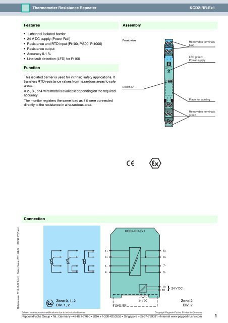
<strong>Thermometer</strong> <strong>Resistance</strong> <strong>Repeater</strong><strong>KCD2</strong>-<strong>RR</strong>-<strong>Ex1</strong>FeaturesAssembly• 1-channel isolated barrier• 24 V DC supply (Power Rail)• <strong>Resistance</strong> and RTD input (Pt100, Pt500, Pt1000)• <strong>Resistance</strong> output• Accuracy 0.1 %• Line fault detection (LFD) for Pt100Front view1324Removable terminalsblueLED green:Power supplyFunction<strong>KCD2</strong>-<strong>RR</strong>-<strong>Ex1</strong>PWRThis isolated barrier is used for intrinsic safety applications. Ittransfers RTD resistance values from hazardous areas to safeareas.A 2-, 3-, or 4-wire mode is available depending on the requiredaccuracy.The monitor registers the same load as if it were connecteddirectly to the resistance in a hazardous area.Switch S1S1II5 67 89 10IPlace for labelingRemovable terminalsgreenConnectionRelease date 2010-11-22 14:41 Date of issue 2011-04-04 190247_ENG.xmlZone 0, 1, 2Div. 1, 24+3+1-2-Power Rail<strong>KCD2</strong>-<strong>RR</strong>-<strong>Ex1</strong>24 V DC6+8+7-5-9+10-24 V DCZone 2Div. 2Subject to reasonable modifications due to technical advances.Copyright Pepperl+Fuchs, Printed in GermanyPepperl+Fuchs Group • Tel.: Germany +49-621-776-0 • USA +1-330-4253555 • Singapore +65-67-799091 • Internet www.pepperl-fuchs.com 1
Technical data<strong>KCD2</strong>-<strong>RR</strong>-<strong>Ex1</strong>Release date 2010-11-22 14:41 Date of issue 2011-04-04 190247_ENG.xmlGeneral specificationsSignal typeSupplyAnalog inputConnection Power Rail or terminals 9+, 10-Rated voltage19 ... 30 V DCRipplewithin the supply toleranceRated current< 20 mAPower consumption0.35 W (24 V and 1 mA sense current)InputConnection terminals 1, 2, 3, 4Line fault detectionyes , at Pt100Lead resistance≤ 10 % of resistance valueTransmission range0 ... 10 mAAvailable voltage9 VLead monitoring50 nAOutputConnection terminals 5-, 7-, 6+, 8+Current0 ... 10 mAAvailable voltage0 ... 7 VFault signal< 10 Ω or > 400 Ω, depending on lead disconnected (measuring current ≤ 1mA)Transfer characteristicsDeviationI m ≥ 1 mA: ± 0.1 % of R m or ± 0.1 Ω (the larger value is applicable)I m < 1 mA: accuracy reduces in proportion to I m .e. g. I m = 0.1 mA: ± 1 % of R m or 1 Ω (the larger value is applicable).Influence of ambient temperature I m ≥ 1 mA, R m ≥ 100 Ω : 0.01 %/K in the range -20 ... +60 °C (253 ... 333 K)I m < 1 mA or R m < 100 Ω: temperature stability reduces in proportion to I m or R mRise time signal response time ≤ 2 ms (10 ... 90 %)response to application of I m : R m > 50 Ω and I m < 5mA: < 5msresponse to application of I m : R m > 30 Ω and I m < 5mA: < 10msresponse to application of I m : R m > 18 Ω and I m < 5mA: < 20msElectrical isolationOutput/power supplyDirective conformityElectromagnetic compatibilityfunctional insulation, rated insulation voltage 50 V ACDirective 2004/108/EC EN 61326-1:2006ConformityElectromagnetic compatibility NE 21Protection degree IEC 60529Protection against electric shock UL 61010-1Ambient conditionsAmbient temperature-20 ... 60 °C (-4 ... 140 °F)Mechanical specificationsProtection degreeIP20Massapprox. 100 gDimensions12.5 x 114 x 124 mm (0.5 x 4.5 x 4.9 in) , housing type A2Data for application in connectionwith Ex-areasEC-Type Examination Certificate BASEEFA 10 ATEX 0061 , for additional certificates see www.pepperl-fuchs.comGroup, category, type of protection ¬ II (1)GD, I (M1), [Ex ia] IIC, [Ex iaD], [Ex ia] I (-20 °C ≤ T amb ≤ 60 °C) [circuit(s) in zone 0/1/2]Voltage U o 12.4 VCurrent I o 17.4 mAPower P o 54 mWSupplyMaximum safe voltage U m253 V (Attention! The rated voltage can be lower.)Type of protection [EEx ia]OutputMaximum safe voltage U m253 V (Attention! The rated voltage can be lower.)Statement of conformityBASEEFA 10 ATEX 0062X , observe statement of conformityGroup, category, type of protection, ¬ II 3G Ex nA II T4temperature classificationElectrical isolationInput/Outputsafe electrical isolation acc. to IEC 60079-11, voltage peak value 375 VInput/power supplysafe electrical isolation acc. to IEC 60079-11, voltage peak value 375 VDirective conformityDirective 94/9/EC EN 60079-0:2006, EN 60079-11:2007, EN 60079-15:2005, EN 61241-11:2006International approvalsSubject to reasonable modifications due to technical advances.Copyright Pepperl+Fuchs, Printed in GermanyPepperl+Fuchs Group • Tel.: Germany +49-621-776-0 • USA +1-330-4253555 • Singapore +65-67-799091 • Internet www.pepperl-fuchs.com 2
Technical data<strong>KCD2</strong>-<strong>RR</strong>-<strong>Ex1</strong>FM approvalControl drawing116-0129 (cFMus)UL approvalControl drawing116-0332 (cULus)IECEx approval IECEx BAS 10.0024IECEx BAS 10.0025XApproved for[zone 0] [Ex ia] IIC, [Ex iaD], [Ex ia] IEx nA II T4General informationSupplementary informationEC-Type Examination Certificate, Statement of Conformity, Declaration of Conformity, Attestation ofConformity and instructions have to be observed where applicable. For information see www.pepperlfuchs.com.Release date 2010-11-22 14:41 Date of issue 2011-04-04 190247_ENG.xmlSubject to reasonable modifications due to technical advances.Copyright Pepperl+Fuchs, Printed in GermanyPepperl+Fuchs Group • Tel.: Germany +49-621-776-0 • USA +1-330-4253555 • Singapore +65-67-799091 • Internet www.pepperl-fuchs.com 3
Technical data<strong>KCD2</strong>-<strong>RR</strong>-<strong>Ex1</strong>Additional informationFunctionWhen a signal converter, a DCS or PLC is connected to terminals 5, 6, 7, and 8 (control side), the measuring current istransferred to terminals 2 and 4 (field side). The resulting voltage at terminals 1, and 3 is transferred to terminals 5, 6, 7, and 8.In the case of fast multiplex input cards, transmission problems might be experienced in connection with low resistance valuesand/or high sensor currents. For data see rise time.Connection types control side (safe area)2-wire mode3-wire modenegativemeasuring line3-wire modepositivemeasuring line4-wire mode8 6 5 7 8 6 5 7 8 6 5 7 8 6 5 7+ + - -+ + - -+ + - -+ + - -DCS, PLC,SignalconverterDCS, PLC,SignalconverterDCS, PLC,SignalconverterDCS, PLC,SignalconverterConnection types field side (hazardous area)The resistance in the hazardous area can be measured with a 2-, 3- or 4-wire mode.• 2-wire mode:Link terminals 1 and 2 and terminals 3 and 4. Connect the resistance to terminal 4 and terminal 2. Switch S1 in the position II.• 3-wire mode:Link terminals 1 and 2. Connect the resistance to terminals 3 and 4 and terminal 2. Switch S1 in the position I.• 4-wire modeConnect the resistance to terminals 3 and 4 and terminals 1 and 2. Switch S1 in the position II.Measurement rangeThe resistance repeater can convey a maximum of 10 mA and a maximum of 7 V. The maximum connectable resistance valuecan be derived from the following equation:<strong>Resistance</strong> value = 7 V/measuring currentThe measuring current is determined by control.Measuring current I (mA)108Release date 2010-11-22 14:41 Date of issue 2011-04-04 190247_ENG.xml6420.52 4 6 8 10 12 14 kΩmax. <strong>Resistance</strong>Temperature sensorAn example of the maximum transferable resistance value:• 14 kΩ at 0.5 mA measuring current• 3.5 kΩ at 2 mA measuring currentSubject to reasonable modifications due to technical advances.Copyright Pepperl+Fuchs, Printed in GermanyPepperl+Fuchs Group • Tel.: Germany +49-621-776-0 • USA +1-330-4253555 • Singapore +65-67-799091 • Internet www.pepperl-fuchs.com 4
Technical data<strong>KCD2</strong>-<strong>RR</strong>-<strong>Ex1</strong>Line Fault Detection (LFD)The output will indicate less than 10 Ω or greater than 400 Ω for a lead breakage at terminals 1, 2, 3 or 4 for measuring currentof less than or equal to 1 mA i.e. out of range for Pt100.AccessoriesPower feed module KFD2-EB2The power feed module is used to supply the devices with 24 V DC via the Power Rail. The fuse-protected power feed modulecan supply up to 100 individual devices depending on the power consumption of the devices. A galvanically isolated mechanicalcontact uses the Power Rail to transmit collective error messages.Power Rail UPR-03The Power Rail UPR-03 is a complete unit consisting of the electrical inset and an aluminium profile rail 35 mm x 15 mm. To makeelectrical contact, the devices are simply engaged.Profile Rail K-DUCT with Power RailThe profile rail K-DUCT is an aluminum profile rail with Power Rail insert and two integral cable ducts for system and field cables.Due to this assembly no additional cable guides are necessary.Power Rail and Profile Rail must not be fed via the device terminals of the individual devices!AttentionRelease date 2010-11-22 14:41 Date of issue 2011-04-04 190247_ENG.xmlSubject to reasonable modifications due to technical advances.Copyright Pepperl+Fuchs, Printed in GermanyPepperl+Fuchs Group • Tel.: Germany +49-621-776-0 • USA +1-330-4253555 • Singapore +65-67-799091 • Internet www.pepperl-fuchs.com 5