RSE-1D1 - Ansaldo STS
RSE-1D1 - Ansaldo STS
RSE-1D1 - Ansaldo STS

You also want an ePaper? Increase the reach of your titles
YUMPU automatically turns print PDFs into web optimized ePapers that Google loves.
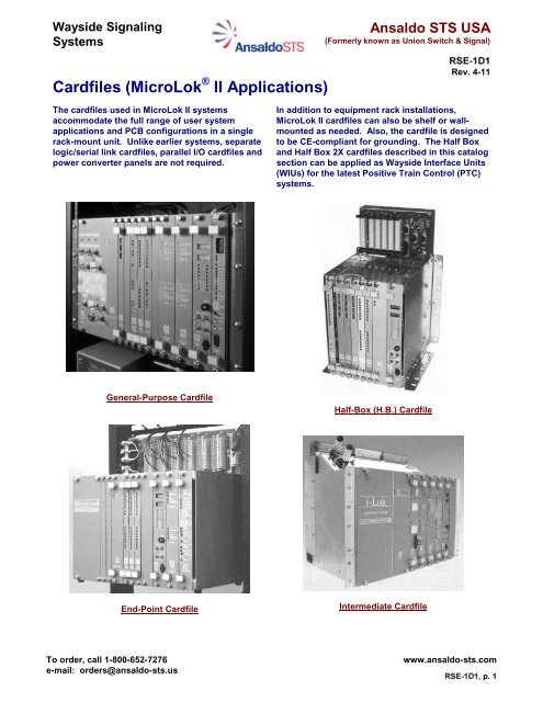
Wayside SignalingSystems<strong>Ansaldo</strong> <strong>STS</strong> USA(Formerly known as Union Switch & Signal)Cardfiles (MicroLok II Applications)Rev. 4-11The cardfiles used in MicroLok II systemsaccommodate the full range of user systemapplications and PCB configurations in a singlerack-mount unit. Unlike earlier systems, separatelogic/serial link cardfiles, parallel I/O cardfiles andpower converter panels are not required.In addition to equipment rack installations,MicroLok II cardfiles can also be shelf or wallmountedas needed. Also, the cardfile is designedto be CE-compliant for grounding. The Half Boxand Half Box 2X cardfiles described in this catalogsection can be applied as Wayside Interface Units(WIUs) for the latest Positive Train Control (PTC)systems.General-Purpose CardfileHalf-Box (H.B.) CardfileEnd-Point CardfileIntermediate CardfileTo order, call 1-800-652-7276e-mail: orders@ansaldo-sts.uswww.ansaldo-sts.comp. 1
(Formerly known as Union Switch & Signal)Cardfiles (MicroLok II Applications)Rev. 4-11MicroLok II General-Purpose CardfileGeneral-Purpose Cardfile (Single and Dual-Motherboard Models)DescriptionThe General-Purpose MicroLok II System cardfilecontains the system’s central controlling logic andcircuits that interface this logic to external circuits.Logic and interface circuits are contained on thefamiliar Eurocard format plug-in printed circuit boards(PCBs). Two versions of this cardfile are available,including a unit with a single motherboard governed byone CPU PCB, and a unit with dual (identical)motherboards that incorporate separate CPU boardsfor their respective sets of PCBs. The dualmotherboardversion allows two MicroLok IIsubsystems to be housed in one cardfile forapplications such as hot standby, and locations wheretwo single-motherboard cardfiles are not required oradequate space is not available.Both cardfiles contain 19 card slots. All external wiringis connected to the cardfile via 48-pin or 96-pinconnector/cable assemblies attached to connectorsalong the rear of the cardfile. In the typical equipmentrack installation, this wiring is routed to separateadjacent terminal strips.To prevent accidental insertion of a PCB in the wrongcardfile slot, each PCB is equipped with male keyingpins. Dual in-line package (DIP) switches within theconnector housings are used to set the cardfile busaddress for communications between the CPU andother PCBs.The MicroLok II General-Purpose cardfile can bemounted in a standard 19-inch equipment rack, or ona wall or shelf using the fiberglass mounting bracketssupplied with the unit.SpecificationsPCB Design/Mounting:Total PCB Slots:Slot Bus Addressing:Upper PCB Connectors:Mounting:Unit Dimensions:Standard Eurocard19 (both single and dualmotherboardmodels)Via 8-rocker DIP switchesin connector housings48 and 96-pin maleStandard 19” (48.25 cm)rack, wall or shelfSee above diagram.Cardfile Mechanical Loads: 1.0g RMS, 0.2”displacement, 5-1000 HzOperating Temperature:Humidity Limit:-40°C to +70°C (-40°F to+158°F)95%, non-condensing, p. 2
Cardfiles (MicroLok II Applications)(Formerly known as Union Switch & Signal)MicroLok II Intermediate Cardfile for LED Signal LocationsRev. 4-11LED 12 Intermediate System CardfileDescriptionThe MicroLok II LED 12 Intermediate System cardfile usesthe basic Eurocard design, which allows plug-in PCBs toform an complete front control/display panel. Severalmodels of plug-in PCB cardfiles that accommodate Ethernetor serial communications to a remote wayside system ofoffice, as well as A<strong>STS</strong> USA or Alstom style VCOR relayoptions for vital power switching.This cardfile incorporates an extended backplanemotherboard with 12 front-accessible cage clampconnectors (Wago brand) that enable direct connection ofexternal I/O wiring to the cardfile. The arrangementeliminates the need for separate rack-mount terminal stripsand/or connector cable assemblies. To aid in field wiring,the connectors are assigned (as labeled) to specific types ofPCBs. Slot-address jumpers for the LED 12 and trackcircuit PCBs (MicroTrax and E-Code) are also located onthe motherboard. Additional jumpers allow for inputs to theLED 12 boards to be shorted together to support ConstantCurrent Regulator (CCR) sharing between LED signaloutputs, without the use of additional external wiring.Other motherboard-mounted devices include and EEPROMfor storing unit-specific configuration data, top-mounted RJ-45 jack for Ethernet communications wiring, and two 25-pin“D” connectors to interface vital or non-vital serialcommunications wiring (when required) to the CPU PCB’sserial ports. These ports also permit daisy-chaining ofseveral LED 12 systems. AREMA (AAR) terminal posts arealso provided for connection of power input wiring (includeswired-in transient voltage protection). These terminals,which incorporate post-to-post straps, are also used toroute VCOR-controlled power and CCR power when theLED 12 PCB is installed.The VCOR relay is housed in the left-hand bay of thecardfile and includes a built-in relay base. Thisarrangement eliminates the need for a separate VCOR rackinstallation outside the cardfile. Both A<strong>STS</strong> USA PN-150Band Alstom B1 relays are provided in the various cardfileoptions (see Ordering Information).Several models of the MicroLok II LED 12 System cardfileinclude an Ethernet Communications Module (ECM) that isstand off-mounted on the back side face of themotherboard. Ethernet communications are enabledthrough Port 4 on the CPU PCB and the Ethernet jack at thetop of the cardfile. Versions of the cardfile not equippedwith the Ethernet capability can be upgraded in the field at alater date by installing the ECM as an add-on component.SpecificationsPCB Design/Mounting:Total PCB Slots: 8Cardfile Connectors:Unit Dimensions:Cardfile Mounting:Cardfile Weight:Operating Temp.:Humidity Limit:Standard Eurocard12 cage clamp connectorsRJ-45 Ethernet Jack (8-pin)2 25-pin “D” connectors (seriallinks)5 AREMA (AAR) terminal postsSee above diagram.Rack or wall (see OrderingInformation)30 lbs. (13.6 kg) - with aminimum card complement.-40°C to +70°C (-40°F to+158°F)0% to 95%, non-condensing, p. 3
(Formerly known as Union Switch & Signal)Cardfiles (MicroLok II Applications)Rev. 4-11MicroLok II Intermediate Cardfile for Incandescent Signal Locations19.0” (48.25 CM)18.2” (46.25 CM)WIRING TERMINALS(WAGO OR BUCHANAN)BATT.TERMINALSSERIALLINKPORTS15.9”(40.39 CM)RELAY BASE(A<strong>STS</strong> USA OR ALSTOM)11.0” (27.94 CM)Intermediate System Cardfile for IncandescentSignal InstallationsDescriptionThe MicroLok II Intermediate cardfile for incandescentsignal locations also utilizes the familiar Eurocarddesign common to other A<strong>STS</strong> USA systems, but alsoincorporates parallel and serial I/O data connectors onits top panel. This cardfile is designed for standard19” rack, shelf or wall mounting and contains slots forup to 20 plug-in PCBs, four of which are typically usedfor various I/O boards. Three wiring terminal blocksare mounted at the top of the unit for all parallel I/Owiring. Depending on the model, these can consist ofthree 22-way screw lock connectors, or two 22-wayplus one 20-way cage clamp connectors. Batterypower to the unit is connected to a pair of standardAREMA (AAR) terminal posts.For installations where the MicroLok II Intermediateunit communicates over a serial link with anotherMicroLok II Intermediate system or controlling vitalprocessor, two 25-pin “D” connectors are provided. Ina typical application, a MicroLok II system serves asthe serial link Master unit to a several MicroLok IIIntermediate Slave units.A bay in the MicroLok II Intermediate cardfile containseither an A<strong>STS</strong> USA PN-150B vital relay, or Alstom B1vital relay, which serves as the system Vital Cut-OffRelay (VCOR). This relay is controlled by the CPUboard and switches power to all vital outputs.SpecificationsPCB Design/Mounting:Total PCB slots: 20Mounting:Unit Dimensions:Parallel I/O Wiring:Serial Data Ports:Power Connections:Operating Temp.:Humidity limit:Standard EurocardStandard 19” (48.25 cm)rack, wall or shelfSee above diagram.Three 22-way screw lockconnectors (Buchanan)Two 22-way + one 20-waycage clamp (Wago)connectorsTwo 25-pin “D”, RS-485Two standard AREMA(AAR) terminal posts.-40°C to +70°C (-40°F to+158°F)95%, non-condensing, p. 4
Cardfiles (MicroLok II Applications)(Formerly known as Union Switch & Signal)MicroLok II End Point CardfileRev. 4-11End Point CardfileDescriptionThe MicroLok II End Point cardfile features frontaccessiblediscrete-wire connectors that eliminate theneed for separate specialized PCB directconnector/cable assemblies. These connectors, alongwith front serial link ports and an integral Vital Cut-OffRelay (VCOR) make the End Point unit very simple toinstall, configure and replace.The 19” (48.25 cm) End Point cardfile is shipped withrear edge wall mounting ears already attached; kits areavailable for conversion to equipment rack or shelfmounting (see ordering information). Slots are providedfor up to 10 PCBs including one DC Lamp Driver, up tofive Mixed Vital I/O, one Power Supply, one CPU and upto two Track Circuit boards (MicroTrax or E-Code type).All PCBs are standard MicroLok II models. The left-handbay of the cardfile houses the VCOR relay with relaymounting base (A<strong>STS</strong> USA or Alstom type) built in.External I/O wiring is brought to eight Wago style cageclamp connectors accessible at the top front of thecardfile. Board addressing for the Lamp Driver PCB andTrack Circuit PCBs is accomplished with jumpersadjacent to the respective Wago connectors, whileMixed Vital I/O PCB addressing is performed in theapplication software. No connector-mounted addressingswitches are required.The End Point cardfile also incorporates two DB-9 25-pin“D” connectors to allow vital or non-vital serial linking ofthe unit to other MicroLok-based systems. Theseparallel-wired connectors also permit “daisy-chain”linking of several End Point units.End Point unit operating power is brought to AREMA(AAR) style terminal posts on the left-hand end of theterminal board. Five such terminals are provided,including two for connection of system battery power andthree additional posts that allow signal lamp poweringfrom a battery source isolated from the system batterysource. Post-to-post straps are provided for configuringthe above lamp driving power setup.SpecificationsPCB Design/Mounting: Standard EurocardTotal PCB slots: 10Mounting:Unit Dimensions:Parallel I/O Wiring:Serial Data Ports:Power Connections:Fuse:Operating Temp.:Humidity limit:Standard 19” (48.25 cm) rack,wall or shelf (shipped with wallmountbrackets; see orderinginformation for kits)See above diagram.Six 32-terminal (16+/16-) cageclamp connectors (Lamp Driverand Mixed I/O PCBs)Two 5-terminal cage clampconnectors (Track Circuit PCBs)Two 25-pin “D”, RS-232/423Five standard AREMA (AAR)terminal posts, with straps(system battery and isolated lamppower option)10A-40°C to +70°C (-40°F to +158°F)95%, non-condensing, p. 5
(Formerly known as Union Switch & Signal)Cardfiles (MicroLok II Applications)Rev. 4-11MicroLok II Half-Box (H.B.) CardfileHalf Box (H.B.) CardfileDescriptionThe MicroLok II Half Box (H.B.) cardfile is designed forwayside installations where mounting space is limited (e.g.equipment case) or a full size equipment house is notavailable. As such, it serves as a bridge between thelarge19-inch (48.25 cm) MicroLok II cardfiles and thecompact MicroLok Object Controller. The H.B. cardfile isonly 11 (27.9 cm) inches wide and is equipped withbrackets for wall or shelf mounting. Only six of the unit’s 10available slots require field configuration of I/O PCBs; theCPU and Power Supply/CPS boards’ location are fixed forall applications. The unit can also be outfitted with a frontattachedLocal Control Panel.The internal motherboard is extended above the cardfile toprovide a convenient panel to attach I/O PCB cables, serialcables, power input wiring and VCOR wiring. Six male-pinconnectors are provided on this panel to attach standard48-way MicroLok II cables (refer to <strong>RSE</strong>-1D2 for thesecables). Only the 96-pin cable for the 32/32 Non-Vital I/OPCB (N17061501) connector/cable assembly is notcompatible with the H.B. unit.Battery and VCOR wiring is attached via a 4-way Wagobrand connector in the upper right corner of the panel.Below this connector are three “D” style plugs forconnection of RS-485 or RS-232 serial communications linkwiring. The two RS-485 plugs are switch-selectable. Anoptional Serial-To-Ethernet Converter PCB can be installedto enable Internet-based remote communications. Thisboard is mounted inside the cardfile’s rear cover andprovides a top-accessible RJ-45 jack for Ethernetcommunications.Unit power is controlled by a standard 2-position toggleswitch, while the unit’s current draw is protected with a 10Amp fuse, also on the upper panel.SpecificationsPCB Design/Mounting:Unit Dimensions:Unit Mounting:Unit Weight (Approx.):Input Power:Starting Voltage:Fuse:Surge Protection:Power & VCOR Wiring:Total Field PCB Slots: 6Applicable I/O PCBs:Applicable II Cables:Serial Ports:Ethernet Port (Option):Operating Temperature:Humidity Limit:Standard EurocardSee above diagramShelf or wall (via brackets)7.5 lb. (3.4 kg)9.8 to 16.2 Vdc (12.0 Vdc nom.)11.2 Vdc (min.)10A (front panel mounted)5W, 16V Transzorb (5KP16A)Four cage clamp terminalsAll except 32/32 Non-Vital I/OPCB N17061501 (see <strong>RSE</strong>-1D2.2 and -1D2.3)All except those with 96-pinconnectors (see <strong>RSE</strong>-1D2)Two 9-pin “D” connectors: RS-485 (switch-selectable ports)One 25-pin “D” connector: RS-232One 9-pin “D” connector: RS-232RJ-45 jack-40°C to +70°C (-40°F to+158°F)95%, non-condensing, p. 6
Cardfiles (MicroLok II Applications)(Formerly known as Union Switch & Signal)Half Box 2X CardfileDescriptionThe MicroLok II Half-Box 2X (HB2X) Cardfile isderived from A<strong>STS</strong> USA’s highly successfulHalf-Box cardfile (see catalog page 6). It can beconfigured as a multi-purpose vital and/or nonvitalmonitoring and control system for railroad ormass transit wayside interlocking applications,including railroad PTC configurations. This unithas 14 user-configurable slots and is designedfor wall or shelf mounting.The HB2X cardfile accommodates moststandard MicroLok II plug-in PCBs. Threedouble-width PCB slots are reserved for thePower Supply PCB in Slots 15 and 16. Slots 17and 18 are reserved for the vital CPU board,while slots 19 and 20 are held for the Genisys IIstyle non-vtial CPU board (when used). Theremaining 14 slots can take any standardMicroLok II I/O PCBs. Refer to the orderingtabulation on catalog page 9 for other PCBassignment information. The HB2X cardfile isequipped with an upper and a lowermotherboard. Connectors for external cablesare mounted on the front of the uppermotherboard.A 6-point, removable WAGO brand power connector ismounted on the front of the upper motherboard. Thisconnector is used for the battery input and VCOR coilwiring. One pin of this connector is routed internally tothe shutdown function of the Power Supply PCB. Thefunction allows the user to shut down the system usingan external power supply. The lower motherboard isequipped with a 6-pin WAGO brand connector to provideauxiliary (external power supply) power to the HB2X inplace of a Power Supply PCB.The HB2X cardfile contains three vital and/or three nonvitalcommunications ports for external communications.An additional port is used for internal communicationsbetween the non-vital and vital CPU PCBs, as requiredby the application. An optional Ethernet PCB(N17006202) can be plugged onto the rear of the HB2Xupper motherboard. The Ethernet port is accessible ontop of the cardfile when the Ethernet PCB is installed.SpecificationsPCB Design/Mounting:Unit Dimensions:Unit Mounting:Unit Weight:Standard EurocardSee above diagramShelf or wall (via brackets)22.25 lb. (10 kg)Input Power:Fuse:Surge Protection:Wiring Connections:Serial Ports:Ethernet Port (Option):Weight*:Operating Temperature:Humidity Limit:Rev. 4-119.8 to 16.2 Vdc (12.0 Vdcnom.)10A5W/16V TranzorbUpper: 6-point WAGO: Batt.input and VCOR wiringLower: 6-point WAGO:External power (in place ofPower Supply PCB)Two 9-pin “D” connectors:RS-485 (switch-selectableports)One 25-pin “D” connector:RS-232One 9-pin “D” connector:RS-232RJ-45 jack (cardfile topmounted)22.25 lbs. (10 kg), *typicalwith all PCBs installed.-40°C to +70°C (-40°F to+158°F)95%, non-condensing, p. 7
(Formerly known as Union Switch & Signal)Cardfiles (MicroLok II Applications)Rev. 4-11Split-Motherboard Cardfile (With Integral DB-9 Serial Ports)DescriptionThe Split-Motherboard cardfile incorporates the samebasic enclosure design, mounting and I/O wiringprovisions as the General-Purpose cardfile. However,this cardfile features a built-in serial port backplanePCB, adjacent to the main motherboard, that containssix 9-pin serial port connectors. This cardfile is typicallyused in mass transit ATC applications consisting ofredundant MicroLok II cardfiles that are wired to enableautomatic failover. A “Serial Link Relay” PCB is pluggedinto this motherboard PCB (of both MicroLok II units) toprovide a path for failover communications. ThesePCBs and associated VCOR relays inter-operate toestablish which MicroLok II is online and which is instandby. Included in the serial port backplane PCB areRS-485, RS-423/232 port and RS-232 ports, several ofwhich are field-configurable for vital or non-vital serialcommunications.There are 16 remaining slots in the Split- Motherboardcardfile. These are designed to accept the standardMicroLok II CPU, I/O and Power Supply PCBs using 48-pin or 96-pin connectors. The CPU is internally wired tothe serial-port backplane PCB as part of the inter-MicroLok II failover configuration.Although the Split-Motherboard Cardfile was originallydesigned for ATC systems with redundant MicroLok IIunits, it can be used in entirely different applications.Contact your A<strong>STS</strong> USA Account Executive to discusspotential uses.SpecificationsPCB Design/Mounting:Total PCB Slots: 17Slot Bus Addressing:Upper PCB Conns:Backplane Serial Ports:Mounting:Unit Dimensions:Standard EurocardVia 8-rocker DIP switchesin connector housings48 and 96-pin male2 permanent RS-4852 jumper-selectable RS-4851 jumper-selectable RS-423/2321 jumper-selectable RS-232Standard 19” (48.25 cm)rack, wall or shelfSee above diagramCardfile Mech. Loads: 1.0g RMS, 0.2”displacement, 5-1000 HzOperating Temp.:Humidity Limit:-40°C to +70°C (-40°F to+158°F)95%, non-condensing, p. 8
Cardfiles (MicroLok II Applications)(Formerly known as Union Switch & Signal)Ordering InformationRefer to tabulations for ordering information on theMicroLok II-based cardfiles.Refer to <strong>RSE</strong>-1D2 for ordering information on theMicroLok II plug-in cardfile components.Rev. 4-11Refer to <strong>RSE</strong>-1G2 for Positive Train Control (PTC)Wayside Interface Unit (WIU) applications of Half-Box and Half-Box 2X cardfiles.Contact your A<strong>STS</strong> USA Account Executive foradditional information on special-applicationMicroLok II cardfiles (e.g. Sleep Mode, AF-900Track Circuit control).MicroLok II CardfilesMotherboard Built-In Signal LampOrder No. Type Design VCOR Relay (1) Driver PCB Type Ethernet PortN16902101 General Purpose Single -- Incandescent --N16905301 General Purpose Dual (2) -- Incandescent --N16903101 General Purpose Split (3) -- Incandescent --N18003901 H.B. (4) Single -- Incand. or LED XN18005201 HB2X (5) Single -- 'Incand. or LED XN18005301 HB2X (6) Single -- 'Incand. or LED XN34600401 Intermediate Single PN-150B Incandescent --N34600402 Intermediate Single PN-150B Incandescent --N34600403 Intermediate Single Type B1 Incandescent --N34600404 Intermediate Single Type B1 Incandescent --N18002701 End Point Single PN-150B Incandescent --N18002801 End Point Single Type B1 Incandescent --N18003001 LED 12 Intermed. Single PN-150B LED --N18003002 LED 12 Intermed. Single PN-150B LED XN18003101 LED 12 Intermed. Single Type B1 LED --N18003102 LED 12 Intermed. Single Type B1 LED XNote (1): A<strong>STS</strong> USA PN-150B or Alstom Type B1Note (2): Contains two equal-capacity sets of card slots.Note (3): Smaller motherboard for serial port interface only.Note (4): General-purpose "Half-Box" cardfile. See <strong>RSE</strong>-1A14 for details.Note (5): All PCB slots equipped with 48-pin connectors. Cardfile cannot use Non-Vital32/32 I/O PCB N17061501Note (6): Slots 1 - 3 equipped with 96-pin connectors for Non-Vital 32/32 I/O PCBN17061501Cardfile Mounting HardwareOrder No. Description NotesM451811-4501 Mounting Bracket: Right-Hand (1)M451811-4502 Mounting Bracket: Left-Hand (1)M18004301 Mounting Bracket: Right-Hand (2)M18004302 Mounting Bracket: Left-Hand (2)X18000802 Rack Mounting Kit for LED 12 intermediate Cardfiles --X180025021 Shelf Mounting Kit for LED 12 Intermediate Cardfiles --Note (1): For General Purpose (single and dual motherboard) andIntermediate cardfiles only.Note (2): For HB2X cardfiles onlyMicroLok® is a registered trademark of <strong>Ansaldo</strong> <strong>STS</strong> USA, Inc., p. 9
, p. 10