SM-6495 - Ansaldo STS
SM-6495 - Ansaldo STS
SM-6495 - Ansaldo STS

You also want an ePaper? Increase the reach of your titles
YUMPU automatically turns print PDFs into web optimized ePapers that Google loves.
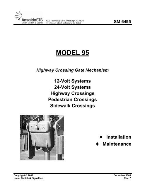
1000 Technology Drive, Pittsburgh, PA 15219645 Russell Street, Batesburg, SC 29006 <strong>SM</strong> <strong>6495</strong>MODEL 95Highway Crossing Gate Mechanism12-Volt Systems24-Volt SystemsHighway CrossingsPedestrian CrossingsSidewalk Crossings♦ Installation♦ MaintenanceCopyright © 2008 December 2008Union Switch & Signal Inc. Rev. 7
NoticesProprietary NoticeThis document and its contents are the property of Union Switch & Signal Inc. (hereinafter US&S).This document has been furnished to you on the following conditions: no right or license under anypatents or any other proprietary right in respect of this document or its content is given or waived insupplying this document. This document or its content are not to be used or treated in any mannerinconsistent with the rights of US&S, or to its detriment, and are not to be copied, reproduced,disclosed to others, or disposed of except with the prior written consent of US&S.IMPORTANT NOTICEThis document and its contents are the property of Union Switch & Signal Inc. (hereinafter US&S).This document has been furnished to you on the following conditions: no right or license under anypatents or any other proprietary right in respect of this document or its content is given or waived insupplying this document. This document or its content is not to be used or treated in any mannerinconsistent with the rights of US&S, or to its detriment, and are not to be copied, reproduced,disclosed to others, or transferred without the prior written consent of US&S.<strong>SM</strong> <strong>6495</strong>, Rev. 7, December 2008i
Revision HistoryRevision HistoryRev. Date Nature of RevisionOriginal September 1996 Original Issue1 March 19992 March 2003 Added new cam clamp in the parts list and updated the parts lists andfigures in general. Added Pedestrian Gate Arm Shield information.Incorporated terminal block changes. Modified the Test Check List (Table2-4). Miscellaneous format and editorial changes.3 September 2003 Incorporated ECO EM-2035. Incorporated information on the redesignedPower Down Module into the manual and added a new section on itsinstallation.Incorporated ECO EM-2006. Added information on the torque readings forthe counterweight installation to include readings with the new torquewrench being supplied as part of the Torque Wrench Kit (PN 467000-03).Miscellaneous format and editorial changes.4 March 2005 Incorporated ECO EM-2177 – Corrected part numbers. Corrected themotor part number in the parts list. Removed the lists of X-bills frommanual and put the individual parts in the parts lists.Incorporated ECO EM-2178 – Revised Figures A-4, A-5, A-6, and A-7 toinclude the new snub diode. Added specific part numbers to the parts lists.Items 300, 305, 310, 315 and 320 were added to the parts list forN46782101 and N46782001.Incorporated ECO EM-2215A – Removed the stiffener from the parts listand revised Figures A-4, A-5, A-6, and A-7 to reflect the absence of thestiffener.In addition, modified the Warning at the beginning of Section 3 to accountfor other mechanisms at a crossing.Included maintenance switch installation in the manual.Incorporated ECO EM-2221 – Changed part number X46703701 toX46703702.Incorporated ECO EM-2232 - Modified wiring diagrams.Incorporated CRS-01341 – Added Safety Consideration in Section 3.1 toprevent backfeed of other gate mechanisms at a crossing when performingmaintenance on one gate mechanism.Miscellaneous format and editorial changes.5 July 2005 Incorporated ECO EM-2283 - Added new version of Figure 2- 5.Corrected identification of Item 320 in Tables 5-2, 5-3, and 5–4.ii <strong>SM</strong> <strong>6495</strong>, Rev. 7, December 2008
Revision HistoryRev. Date Nature of Revision6 June 2006 Incorporated ECO EM-1890 – Corrected the description for Part No.J0523620003 in Tables 5-2, 5-3, and 5-4.Incorporated ECO EM-2177 – Changed part number J0702051208 for gearmotor to N46703602 in Table 5-2.Incorporated ECO-EM-2277A – Added new part number PN46716401 andthe description for the relay in Table 5-6.Incorporated ECO EM-2308 – Changed the part number and name ofN46709102, Toggle Switch Assembly Retrofit to N46790104, ToggleSwitch Assembly Wires in Table 5-10.Incorporated ECO EM-2352 – Added information on the additionalPedestrian Mechanism relay. Added new Section 5.8, revised Table 5-9,and revised Figure 5-14.Incorporated ECO EM-2356B – Added Warning Label, PN M46717401 toTable 5-11.Incorporated ECO EM-2387 – Added parts list for the Snub ComponentsUpgrade kit to the manual as Table 5-16.Incorporated ECO EM-2515A – Figure 2-6 was revised to include the latestrevision of Drawing 467173.Incorporated ECO EM-2564, added new Section 4.3 on “severe weathershocks” and added part number 46701402 to Tables 5-2, 5-3, and 5-4.Added new part number N46780202 (24-Volt Vital Mechanism).Replaced Section 3.2.10 with new procedure requiring disassembly of thegear motor to eliminate grounds in the motor rather than just blowing themotor out through the brush access ports.7 December 2008 Incorporated ECO EM-3028 – Added part number N156683 to Table 5-5,Item Number 40.Incorporated ECO EM-2712 – Revised Tables 5-5 and 5-7. RevisedFigures 5-10 and 5-12. Electrical assemblies changed.Incorporated ECO EM-2709 – Revised Tables 5-6, 5-8, and 5-9. RevisedFigures 5-11, 5-13, and 5-14. Gate mechanism non-vital relay covereliminated.Incorporated ECO EM-2660 – Revised Table 5-17. Conversion bracketassembly part number changed.Incorporated ECO EM-2647 – Revised Tables 5-7 and 5-8. Resistor partnumber changed.Incorporated ECO EM-2684 – Revised Table 5-10 and Figure 5-16.<strong>SM</strong> <strong>6495</strong>, Rev. 7, December 2008iii
Revision Historyiv <strong>SM</strong> <strong>6495</strong>, Rev. 7, December 2008
Table of ContentsTable of Contents1. INTRODUCTION................................................................................................................................1-11.1. Description and General Operation ..........................................................................................1-11.2. Reference Documents ..............................................................................................................1-31.3. Parts List Ordering References.................................................................................................1-31.4. Major Installation Parts .............................................................................................................1-42. INSTALLATION.................................................................................................................................2-12.1. Introduction ...............................................................................................................................2-12.1.1. Required Tools..............................................................................................................2-12.1.2. Foundations ..................................................................................................................2-12.2. Mast Mounting ..........................................................................................................................2-12.2.1. Mast Mounting for Sidewalk Gate Mechanisms............................................................2-22.2.2. Pedestrian Gate Shield Installation...............................................................................2-42.3. Power and Control Wiring .........................................................................................................2-52.3.1. Power Supply Filtering and Regulation Test for Non-Battery Operation for12 and 24 VDC Systems...............................................................................................2-62.3.2. Wiring Diagram for 12-Volt Systems.............................................................................2-72.3.3. Wiring Diagram for 24-Volt Systems.............................................................................2-72.3.4. Wiring Diagram for 3-Wire Control 12-Volt Systems ....................................................2-72.3.5. Wiring Diagram for Pedestrian Mechanism 12-Volt Systems.......................................2-82.4. Spring Buffer Adjustment........................................................................................................2-152.4.1. Horizontal (Down) Buffer Adjustment ........................................................................ 2-152.4.2. Vertical (Up) Buffer Adjustment ................................................................................. 2-152.5. Torque Testing and Adjustments............................................................................................2-152.5.1. Torque Testing (Not required for Sidewalk Gate Mechanisms)................................. 2-152.5.2. Horizontal Adjustment................................................................................................ 2-162.5.3. Vertical Adjustment .................................................................................................... 2-172.6. Cam Adjustment .....................................................................................................................2-172.7. Gate Arm Ascent and Descent Time Test (12-Volt Systems) ................................................2-182.7.1. Gate Arm Ascent and Descent Time Test (24-Volt Systems) ................................... 2-192.7.2. Circuit Breaker ........................................................................................................... 2-192.8. Test Checklist..........................................................................................................................2-203. GENERAL MAINTENANCE AND TROUBLESHOOTING ...............................................................3-13.1. Safety Considerations at Multiple Gate Locations....................................................................3-13.2. General Maintenance................................................................................................................3-23.2.1. Periodic Maintenance ...................................................................................................3-23.2.2. Control Relays...............................................................................................................3-23.2.3. Contact Adjustments.....................................................................................................3-23.2.4. Electrical Assembly.......................................................................................................3-33.2.5. Hold Clear Device (Brake) Removal/Replacement and Testing Procedure.................3-43.2.6. Gearmotor.....................................................................................................................3-73.2.7. Idler Gear Assembly .....................................................................................................3-83.2.8. Main Shaft and Segment Gear .....................................................................................3-8<strong>SM</strong> <strong>6495</strong>, Rev. 7, December 2008v
Table of Contents3.2.9. Power Down of the Gate Arm .......................................................................................3-93.2.10. Eliminating Brush Dust Related System Grounds in the Gearmotor......................... 3-113.2.11. Installing the Power Down Module Upgrade Kit ........................................................ 3-123.3. Troubleshooting (General)......................................................................................................3-153.3.1. Testing and Troubleshooting the Power Down Module for 12-Volt Systems ............ 3-153.3.2. Testing and Troubleshooting the Power Down Module for 24-Volt Systems ............ 3-163.3.3. Verification of Maintenance Switch Operation ........................................................... 3-164. OPTIONAL EQUIPMENT ..................................................................................................................4-14.1. Heater (Defroster) .....................................................................................................................4-14.1.1. Installation Instructions for Model 95 Gate Mechanism Heater Kit...............................4-14.2. Maintenance Switch..................................................................................................................4-14.3. Severe Weather Shock Option .................................................................................................4-15. PARTS LI<strong>STS</strong> AND EQUIPMENT DIAGRAMS................................................................................5-15.1. Model 95 Gate Mechanism – Mechanical Assembly Parts List(12- and 24-Volt Systems)........................................................................................................5-25.2. Model 95 Pedestrian Gate Mechanism - Mechanical Assembly Parts List ..............................5-65.3. Model 95 Sidewalk Gate Mechanism - Mechanical Assembly Parts List ...............................5-125.4. Model 95 Gate Mechanism Electrical Assembly with PN-150 Relay(12-Volt Systems) (N46782101).............................................................................................5-175.5. Non-Vital Relay Electrical Assembly for 12-Volt Systems (N46782001)................................5-205.6. PN-150 Electrical Assembly for 24-Volt Systems (N46782102).............................................5-235.7. Non-Vital Relay Electrical Assembly for 24-volt Systems (N46782002).................................5-265.8. Non-Vital Pedestrian Mechanism Relays Electrical Assembly for12-Volt Systems (N46782201, N46782202) ..........................................................................5-295.9. Model 95 Maintenance Switch................................................................................................5-315.10. Tool Kit (N46707001).............................................................................................................5-335.11. Recommended Model 95 Non-Vital Gate Mech Spare Parts Kit (X46700016)......................5-345.11.1. Recommended Spare Parts Not Contained in the Spare Parts Kit ........................... 5-345.12. Model 95 Gate Mech Torque Wrench Kit (X46700003) .........................................................5-345.13. Power Down Module Upgrade Kit (X46700031).....................................................................5-355.14. Snub Component Upgrade Kit................................................................................................5-355.15. Accessories for the Model 95 Gate Mechanism .....................................................................5-355.16. Gate Arm Light Fuse Retrofit Kit.............................................................................................5-376. GATE ARM CLEARING GRAPHS....................................................................................................6-17. TECHNICAL SUPPORT ....................................................................................................................7-1vi <strong>SM</strong> <strong>6495</strong>, Rev. 7, December 2008
Table of ContentsList of FiguresFigure 1-1 - Model 95 Gate Mechanism Basic Configurations ................................................................1-2Figure 1-2 - Original and Redesigned Power Down Modules..................................................................1-4Figure 1-3 - Model 95 Gate Mechanism Major Installation Parts.............................................................1-5Figure 2-1 - Completed Pedestrian Crossing Gate Arm Shield Installation.............................................2-5Figure 2-2 - Wiring Diagram for 12-Volt Systems – with Maintenance Switch ........................................2-9Figure 2-3 - Wiring Diagram for 12-Volt Systems – without Maintenance Switch .................................2-10Figure 2-4 - Wiring Diagram for 24-Volt Systems ..................................................................................2-11Figure 2-5 - Wiring Diagram for 3-Wire Control 12-Volt Systems..........................................................2-12Figure 2-6 - Wiring Diagram for Pedestrian Mechanism 12-Volt Systems withMaintenance Switch ..........................................................................................................2-13Figure 2-7 - Wiring Diagram for Pedestrian Mechanism 12-Volt Systems withoutMaintenance Switch ..........................................................................................................2-14Figure 2-8 - Torque Increase/Decrease Diagram ..................................................................................2-16Figure 2-9 - Number 1 Contact...............................................................................................................2-18Figure 3-1 - Hold Clear Device.................................................................................................................3-5Figure 3-2 - Installation Close-up ...........................................................................................................3-10Figure 3-3 - Location of the Power Down Module (Units ManufacturedBefore September 1, 2003) ...............................................................................................3-13Figure 3-4 - Proper Hardware Configuration on Terminal Posts 1C, 2C, and 3C..................................3-14Figure 3-5 - Location of Redesigned Power Down Module on Terminal Posts 1C, 2C, and 3C ..........3-14Figure 5-1 - Model 95 Gate Mechanism – Mechanical Assembly (Sheet 1 of 2)....................................5-4Figure 5-2 - Model 95 Gate Mechanism – Mechanical Assembly (Sheet 2 of 2)....................................5-5Figure 5-3 - Model 95 Pedestrian Gate Mechanism – Mechanical Assembly (Sheet 1 of 4) .................5-8Figure 5-4 - Model 95 Pedestrian Gate Mechanism – Mechanical Assembly (Sheet 2 of 4) .................5-9Figure 5-5 - Model 95 Pedestrian Gate Mechanism – Mechanical Assembly (Sheet 3 of 4) ................5-10Figure 5-6 - Model 95 Pedestrian Gate Mechanism – Mechanical Assembly (Sheet 4 of 4) ...............5-11Figure 5-7 - Model 95 Sidewalk Gate Mechanism – Mechanical Assembly (Sheet 1 of 3)(RH Shown – LH Available)...............................................................................................5-14Figure 5-8 - Model 95 Sidewalk Gate Mechanism – Mechanical Assembly (Sheet 2 of 3)(RH Shown – LH Available)...............................................................................................5-15Figure 5-9 - Model 95 Sidewalk Gate Mechanism – Mechanical Assembly (Sheet 3 of 3)(RH Shown – LH Available)...............................................................................................5-16Figure 5-10 - Model 95 Gate Mechanism Electrical Assembly with PN-150 Relay(12-Volt Systems) ..............................................................................................................5-19<strong>SM</strong> <strong>6495</strong>, Rev. 7, December 2008vii
Table of ContentsFigure 5-11 - Model 95 Gate Mechanism Electrical Assembly with Non-Vital Relay(12-Volt Systems) ..............................................................................................................5-22Figure 5-12 - Model 95 Gate Mechanism Electrical Assembly with PN-150 Relay(24-Volt Systems) ..............................................................................................................5-25Figure 5-13 - Model 95 Gate Mechanism Electrical Assembly with Non-Vital Relay(24-Volt Systems) ..............................................................................................................5-28Figure 5-14 - Non-Vital Pedestrian Mechanism Relay, Electrical Assembly ..........................................5-30Figure 5-15 - Maintenance Switch Retrofit Assembly (N46709202)......................................................5-31Figure 5-16 - Maintenance Switch Installation .......................................................................................5-32Figure 5-17 - Tool Kit (N46707001) .......................................................................................................5-33Figure 5-18 - Gate Arm Light Fuse Retrofit Kit.......................................................................................5-38Figure 6-1 - Ten-Second Gate Arm Clearing Graph ................................................................................6-1Figure 6-2 - Fifteen-Second Gate Arm Clearing Graph ...........................................................................6-2Figure 6-3 - Twenty-Second Gate Arm Clearing Graph...........................................................................6-3viii <strong>SM</strong> <strong>6495</strong>, Rev. 7, December 2008
List of TablesTable of ContentsTable 2-1 - Model 95 Gate Mechanism Counterweight Table .................................................................2-3Table 2-2 - Battery and Wire Requirements.............................................................................................2-5Table 2-3 - Cam Adjustment ..................................................................................................................2-17Table 2-4 - Test Checklist ......................................................................................................................2-20Table 3-1 - Troubleshooting Table for Model 95 Gate Mechanism .......................................................3-15Table 4-1 - Model 95 Heater Kit Ordering Information.............................................................................4-1Table 5-1 - Model 95 Gate Mechanism Configurations ...........................................................................5-1Table 5-2 - Model 95 Gate Mechanism – Mechanical Assembly Parts List for 12- and24-Volt Systems ..................................................................................................................5-2Table 5-3 - Model 95 Pedestrian Gate Mechanism - Mechanical Assembly Parts List ...........................5-6Table 5-4 - Model 95 Sidewalk Gate Mechanism - Mechanical Assembly Parts List............................5-12Table 5-5 - Parts List for the 12-Volt Electrical Assembly with PN-150 Relay.......................................5-17Table 5-6 - Parts List for the 12-Volt Electrical Assembly with Non-Vital Relay ....................................5-20Table 5-7 - Parts List for the 24-Volt Electrical Assembly with the PN-150 Relay.................................5-23Table 5-8 - Parts List for the 24-Volt Electrical Assembly with non-Vital Relay.....................................5-26Table 5-9 - Parts List for the 12-Volt Electrical Assembly for Non-Vital Pedestrian Mechanisms .........5-29Table 5-10 - Model 95 Maintenance Switch Retrofit Assembly (Refer to Figure 5-15and Figure 5-16) ................................................................................................................5-31Table 5-11 - Parts List for Tool Kit (N46707001) ...................................................................................5-33Table 5-12 - Parts List for Spare Parts Kit (N46700016) .......................................................................5-34Table 5-13 - Other Recommended Spare Parts ....................................................................................5-34Table 5-14 - Torque Wrench Kit (X46700003).......................................................................................5-34Table 5-15 - Power Down Module Kit (X46700031) ..............................................................................5-35Table 5-16 - Snub Component Upgrade Kit (X46700038).....................................................................5-35Table 5-17 - Accessories for the Model 95 Gate Mechanism ................................................................5-35Table 5-18 - Parts List for the Gate Arm Light Fuse Retrofit Kit (X46700039) ......................................5-36Table 5-19 - Parts List for the Fuse Holder Assembly (N46719101) (Figure 5-18) ...............................5-37<strong>SM</strong> <strong>6495</strong>, Rev. 7, December 2008ix
Table of Contentsx <strong>SM</strong> <strong>6495</strong>, Rev. 7, December 2008
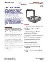
Introduction1. INTRODUCTION1.1. Description and General OperationThe Model 95 Gate Mechanism represents a leap into the use of modern techniques and materials.Its modular design yields an uncluttered mechanism with fewer parts to stock and a simpler unit toservice and maintain.Each unit can be removed and replaced with minimal effort.Each piece of the subassembly is designed to be replaced in the field should the need arise.The unit can be mounted on 4-inch or 5-inch diameter masts with standard hardware.The hold clear device, located on the gearmotor, uses 150 to 160 milliamps on 12 VDC systems and185 milliamps on 24 VDC systems. The brake disengages and allows the arm to lower when a trainapproaches the gate mechanism.The motor is controlled through the Motor Control Relay (MCR) contacts. The MCR is de-energizedwhen the gate is clear, therefore none of the circuit controller contacts carry motor current.The electrical assembly is plate-mounted so that all of the electrical components can be easily removedand replaced.The unique snap-action motor contact extends contact life, while helping to operate the mechanismmore smoothly.There are three basic versions of the Model 95 Gate Mechanism: the Pedestrian Gate, the HighwayCrossing Gate, and the Sidewalk Gate (Figure 1-1). The Model 95 Pedestrian Gate Mechanismincludes crossing gates for both highway crossings and sidewalk crossings on the same mast. TheModel 95 Highway Gate Mechanism includes only the highway crossing gate, and the Model 95Sidewalk Gate Mechanism includes only the sidewalk crossing gate.All gate mechanisms are inspected prior to shipment to ensure that all parts and modules are present,undamaged, and appropriately packaged. If any equipment is missing or damaged, contact the UnionSwitch and Signal Service Shop for replacement items at:Union Switch and Signal645 Russell StreetBatesburg, SC 29006Attn: Customer Service1-800-652-7276<strong>SM</strong> <strong>6495</strong>, Rev. 7, December 2008 1-1
IntroductionSIDEWALK GATEHIGHWAY CROSSING GATEPEDESTRIAN GATENOTE:THE GATE MECHANI<strong>SM</strong>S ARE SHOWNWITH VARIOUS OPTIONAL EQUIPMENTINSTALLED. THE FINAL CONFIGURATIONOF EACH BASIC GATE DEPENDS ON THECUSTOMER’S SPECIFIC REQUIREMENTS.Figure 1-1 - Model 95 Gate Mechanism Basic Configurations1-2 <strong>SM</strong> <strong>6495</strong>, Rev. 7, December 2008
Introduction1.2. Reference DocumentsThe following manuals are part of the family of gate mechanism manuals.<strong>SM</strong> <strong>6495</strong> - Model 95 Highway Gate Crossing Mechanism<strong>SM</strong> <strong>6495</strong>A - Model 95 Gate Mechanism Pedestrian Arm Upgrade Option<strong>SM</strong> <strong>6495</strong>B - Model 95 Highway Crossing Exit Gate Mechanism for Quad Gate Application<strong>SM</strong> <strong>6495</strong>C - Model 95 Maintenance Switch Retrofit Kit Installation\Operation<strong>SM</strong> <strong>6495</strong>D - Model 95 Power-Down Module Installation Kit<strong>SM</strong> <strong>6495</strong>E - Model 95 Gate Arm Light Fuse Retrofit Kit – Installation Instructions1.3. Parts List Ordering ReferencesThis section presents the Assembly Part Order Number along with a breakdown of the specific itempart numbers that constitute that Order Number.In addition to the order numbers listed below special tools and kits are available as follows:Tool Kit – P\N N46707001 – Included with all new Model 95 Gate Mechanisms – See Section 5.10 forthe components in this kit.Spare Parts Kit, Non-Vital – P\N X46700016 – See Section 5.11 for a list of the components in this kit.Torque Wrench Kit – P\N X46700003 – See Section 5.12 for a list of the components in this kit.Power Down Module Upgrade Kit – P\N X46700031 – See Section 0 for a list of the components inthis kit.Maintenance Switch Retrofit Assembly – P\N N46709202 – See Section 5.9 for a list of thecomponents in this kit.Gate Arm Light Fuse Retrofit Kit – P\N X46700039 – See Section 5.16 for a list of the components inthis kit.<strong>SM</strong> <strong>6495</strong>, Rev. 7, December 2008 1-3
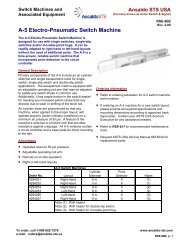
IntroductionNOTEHighway crossing gate mechanisms manufactured on September 1,2003 and later are equipped with a redesigned power down module(Figure 1-2). Gate mechanisms manufactured before this date that needa replacement power down module will require the new Power DownModule Upgrade Kit, X46700031. The old and new modules arefunctionally identical; power down modules that are operating properlydo not need to be replaced.Original DesignRedesigned ModuleFigure 1-2 - Original and Redesigned Power Down Modules1.4. Major Installation PartsThe major installation parts are P\N shown in Figure 1-3.1-4 <strong>SM</strong> <strong>6495</strong>, Rev. 7, December 2008
IntroductionFigure 1-3 - Model 95 Gate Mechanism Major Installation Parts<strong>SM</strong> <strong>6495</strong>, Rev. 7, December 2008 1-5
Introduction1-6 <strong>SM</strong> <strong>6495</strong>, Rev. 7, December 2008
General Maintenance and Troubleshooting2. INSTALLATIONWARNINGTo avoid possible injury to personnel or local traffic, ensure thatRailroad Standard Operating Procedures are followed during installationof the gate mechanism and the gate arm.2.1. IntroductionWhen installing the Model 95 Gate Mechanism, follow your railroad’s standard operating procedures.2.1.1. Required ToolsThe Model 95 Gate Mechanism is designed to be installed with standard tools. All gate mechanismsare shipped with a tool kit (N46707001). This kit includes Allen wrenches for buffer and camadjustments, other various wrenches, and a hold down pin.A torque wrench, or a spring scale, or both will be needed to set the counterweights. Union Switch &Signal offers an optional torque wrench kit (X46700003) that includes a torque wrench and a socket.2.1.2. FoundationsStandard pre-cast or poured concrete may be used as a foundation for the Model 95 Gate Mechanism.Examples are given in the AAR Manual, Part 14. Bolt spacing is a standard four-bolt pattern spaced11-11/16” on center for 5” junction box.2.2. Mast MountingSee Section 2.2.1 for Mounting Sidewalk Gate Mechanisms.To mount the mast, follow the steps below.1. Erect mast with junction box.2. Mount pivot clamp (X46705402). Position top of clamp 42-3/4” above top of the foundation. (Theexact height may need to be adjusted slightly in order to meet the required height of the gate armabove the roadway.)3. Install T-bolts (X46705401), included with mechanism) in back of gate mechanism with threadedportion toward the mast. Place the gate mechanism on top of support clamp. Fasten to mast withclamps and supplied hardware.<strong>SM</strong> <strong>6495</strong>, Rev. 7, December 2008 2-1
General Maintenance and Troubleshooting4. Thread 1-1/2” flexible conduit and 90° elbow coupling (X46700002) to gate mechanism andjunction box.5. Install cable grip conduit for gate arm lights cable, included with gate mechanism.6. Apply a light coating of grease to the main shaft ends. Install gate arm supports (hubs premounted)to keyed main output shaft (Taping the keys to the shaft may assist with installation ofthe gate arm supports). Place washers and nut on the end of shaft and tighten.7. Install conversion bracket assembly (J7051915806) to gate arm supports.8. Install gate arm (rotate gate mechanism so that gate arm will extend parallel to roadway, so trafficis not blocked during installation).9. Install counterweights as follows:a. Install stud plate assemblies (X46700001) on support arms.b. Slide on the proper number and type of counterweights. Refer to the Counterweight Table(Table 2-1).c. Secure with the proper hardware.The number of counterweights required depends on the type and length of the gate arm. The fiberglassand aluminum arms are equal in weight, so they require the same counterweight arrangements. Ifextension arms are not used for longer arms, additional weights must be used to compensate and obtaina proper torque value.10. Rotate the mechanism on the mast so the gate arm is positioned over the roadway before raising thearm when the highway is clear.2.2.1. Mast Mounting for Sidewalk Gate Mechanisms1. Erect mast with junction box.2. Position mechanism approximately 42-3/4” above top of the foundation. (The exact height mayneed to be adjusted slightly in order to meet the required height of the gate arm above thesidewalk.)3. Install T-bolts (X46705401), included with mechanism) in back of gate mechanism with threadedportion toward the mast. Sit gate mechanism on top of support clamp. Fasten to mast with clampsand supplied hardware.4. Thread 1-1/2” flexible conduit and 90° elbow coupling (X46700002) to gate mechanism andjunction box.2-2 <strong>SM</strong> <strong>6495</strong>, Rev. 7, December 2008
General Maintenance and TroubleshootingTable 2-1 - Model 95 Gate Mechanism Counterweight TableGate ArmLengthHorizontal Position TorqueClear Position TorqueClear Position ScaleReadingCounterweight InformationAtMain Shaft(ft-lbs)At Motor Shaft(in-oz)(in-lbs)At MainShaft (ftlbs)At Motor Shaft(in-oz)(in-lbs)Distance“X”(ft)ScaleReading(lbs)QuantitySquare WeightsKit NumberOblong WeightsQuantityKit Number12-15 90-130 17 - 24 1.1 - 1.5 228 42 2.7 5 454 X467401513 X1674016316-18 90-130 17 – 24 1.1 - 1.5 254 47 3 6 426 X4674015219-21 90-130 17 – 24 1.1 - 1.5 339 63 3.9 7 48 10 X467401535 X4674016522-23 90-130 17 – 24 1.1 - 1.5 347 64 4 7 50 11 X4674015424-26 90-130 17 – 24 1.1 - 1.5 370 69 4.3 8 46 13 X467401556 X4674016627-29 90-130 17 – 24 1.1 - 1.5 381 71 4.4 8 47 14 X4674015630-32 90-130 17 – 24 1.1 - 1.5 395 74 4.6 8 49 16 X46740157 7 X4674016733-36 90-130 17 – 24 1.1 - 1.5 382 71 4.4 8 48 11* X4674015810 X4674016937-40 90-130 17 – 24 1.1 - 1.5 398 72 4.5 8 49 12* X46740159* With Extension Arms (Part Number N451484-2403Bold columns indicate inch-ounce or inch-pound torque wrench (X46700003) settings<strong>SM</strong> <strong>6495</strong>, Rev. 7, December 2008 2-3
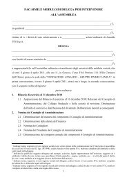
General Maintenance and Troubleshooting5. Install cable grip conduit for gate arm lights cable, included with gate mechanism.6. Install pedestrian gate arm adapter (P/N M46705801) on shaft, insert key into key way, and tightenset screw in adapter.7. Install 3’ aluminum sleeve, weight, and gate arm.2.2.2. Pedestrian Gate Shield InstallationNOTEHighway Crossing Gate Mechanisms manufactured after April 1, 2003,are supplied with the pedestrian gate shield. For models manufacturedbefore this date, a shield kit (Part Number X46712202) can be orderedfrom US&S to add to existing pedestrian gate mechanisms. The kitincludes the shield and necessary mounting hardware.1. Lower the pedestrian gate arm to its horizontal position.2. Disconnect electrical power from the gate mechanism and comply with all railroad/transit authorityprocedures for maintenance lock out/tag out safety instructions. (See Section 3 for additionaldetails.)3. Remove the four screws, washers, and nuts securing the pedestrian gate arm to the cast aluminumadapter arm.4. Position the shield on the side of the pedestrian gate arm opposite the gate mechanism. Insert four(4) 3/8 x 3” screws (P/N J5073490148) and four lock washers (P/N J4751210113) provided withthe shield through the gate arm/adapter arm holes with the screw head towards the counterweightarm. Install the flat washers (P/N J4751200114) and nuts (P/N J480218) on the screws.5. Align the bottom of the shield with the bottom of the pedestrian gate arm and finger tighten thefasteners.6. Using the two holes on the far right of the shield as a guide, locate the corresponding holes in thepedestrian gate arm and punch through the gate arm tape to open the holes.7. Install two (2) screws, lock washers, flat washers, and nuts through these holes.8. Tighten all screws.9. The completed installation will be as shown in Figure 2-1. Return the gate mechanism into service.2-4 <strong>SM</strong> <strong>6495</strong>, Rev. 7, December 2008
General Maintenance and TroubleshootingCOUNTERWEIGHTSGATE ARMSUPPORTCONVERSIONBRACKETASSEMBLYPEDESTRIANGATE ARMSHIELDHIGHWAYCROSSINGGATE ARMPEDESTRIANCROSSINGGATE ARM5A1.0011.00Figure 2-1 - Completed Pedestrian Crossing Gate Arm Shield Installation2.3. Power and Control WiringA maximum of 0.1 ohm resistance is allowed between the battery and the mechanism terminals. Thewiring requirements are given in Table 2-2:Table 2-2 - Battery and Wire RequirementsDistance from Battery to MechanismCable Conductor SizeUp to 60 feetNo. 9 AWG60 to 120 feet No. 6 AWG120 to 250 feet No. 4 AWG (or 2 #6 AWG)Number of Cells (12-Volt System)Gate Arm Length Lead Nickel-Iron Nickel-CadmiumUp to 24 feet 6 9 925 to 42 feet 7 11 11Number of Cells (24-Volt System)Gate Arm Length Lead Nickel-Iron Nickel-CadmiumUp to 24 feet 12 18 1825 to 42 feet 14 22 22For more detailed information, refer to Section 6. These three curves are based on the maximum gatearm clearing times of 10, 15, and 20 seconds. These times are relative to the minimum voltage forvarious cell quantities of lead acid batteries and nickel iron or nickel cadmium batteries. The curvesrepresent maximum gate arm clearing times relative to minimum battery cell voltages. Fully chargedbatteries will decrease the time it takes for the gate arm to clear.<strong>SM</strong> <strong>6495</strong>, Rev. 7, December 2008 2-5
General Maintenance and TroubleshootingCAUTION12 VDC SystemsThe specified operating voltage for the Model 95 is 11 to 16 volts directcurrent. This applies to both the motor supply (B12) and the Up Control.Generally, this power will be supplied from batteries; however, it ispossible to use a power supply without batteries. (This can be done onlyif battery backup is not required in the event of a power failure.) If used,this power supply must be properly filtered and regulated. Otherwise,equipment damage may occur. To check this, perform the test in Section2.3.1.CAUTION24 VDC SystemsThe specified operating voltage for the Model 95 is 21 to 28 volts directcurrent. This applies to both the motor supply (B24) and the Up Control.Generally, this power will be supplied from batteries; however, it ispossible to use a power supply without batteries. (This can be done onlyif battery backup is not required in the event of a power failure.) If used,this power supply must be properly filtered and regulated. Otherwise,equipment damage may occur. To check this, perform the test in Section2.3.1.2.3.1. Power Supply Filtering and Regulation Test for Non-Battery Operation for12 and 24 VDC Systems1. Set a voltmeter on the VDC scale.2. Place the voltmeter negative (black) lead on terminal 6B of the gate mechanism.3. Place the voltmeter positive (red) lead on terminal 2C of the gate mechanism.4. The voltage should read no more than 16 VDC on 12-volt systems and 28 VDC on 24-voltsystems.5. Move the positive (red) lead of the voltmeter to terminal 1C.6. The voltage should read no more than 16VDC on 12-volt systems and 28 VDC on 24-volt systems.2-6 <strong>SM</strong> <strong>6495</strong>, Rev. 7, December 2008
General Maintenance and Troubleshooting7. With the crossing operating and the gate arm going up, make certain that the voltage does not fallbelow 11VDC on 12-volt systems and 21 VDC on 24-volt systems.8. Place the voltmeter on the AC scale. The voltmeter must block the DC voltage. For somevoltmeters, such as most analogs, it may be necessary to place a 0.1μF to 1μF capacitor in serieswith the meter. An oscilloscope can be used as an alternative.9. Again, with the crossing operating and the gate arm going up, check that the voltmeter does notread more than 3 VAC (this is checking the AC).2.3.2. Wiring Diagram for 12-Volt SystemsConnect the wires to the Terminal Board as shown in Figure 2-2 or Figure 2-3 for 12-volt systems.NOTEThe wiring diagrams in Figure 2-2 and Figure 2-3, have the spare,unused terminals on the lower terminal block. Gate mechanismsproduced prior to July 5, 2004, have wiring arrangements that had thespare/unused terminals on the upper block.2.3.3. Wiring Diagram for 24-Volt SystemsConnect the wires to the Terminal Board as shown in Figure 2-4 for 24-volt systems.NOTEThe wiring diagram in Figure 2-4 has the spare, unused terminals on thelower terminal block. Gate mechanisms produced prior to July 5, 2004,have wiring arrangements that had the spare/unused terminals on theupper block.2.3.4. Wiring Diagram for 3-Wire Control 12-Volt SystemsConnect the wires to the Terminal Board as shown in Figure 2-5 for 3-wire control 12-volt systemsNOTEThe wiring diagram in Figure 2-5 has the spare, unused terminals on thelower terminal block. Gate mechanisms produced prior to July 5, 2004,have wiring arrangements that had the spare/unused terminals on theupper block.<strong>SM</strong> <strong>6495</strong>, Rev. 7, December 2008 2-7
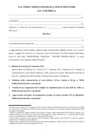
General Maintenance and Troubleshooting2.3.5. Wiring Diagram for Pedestrian Mechanism 12-Volt SystemsConnect the wires to the Terminal Board as shown in Figure 2-6 and Figure 2-7 for 12-volt systemsNOTEThe wiring diagrams in Figure 2-6 and Figure 2-7 have the spare,unused terminals on the lower terminal block. Gate mechanismsproduced prior to July 5, 2004, have wiring arrangements that had thespare/unused terminals on the upper block.2-8 <strong>SM</strong> <strong>6495</strong>, Rev. 7, December 2008
General Maintenance and Troubleshooting4A4B4C5A 6A5B6B5C6CPOWERDOWNMODULER2 R3SNUBRESLIMRESR1R4OPTIONAL} HEATERINDICATION(SEE NOTE 1)GATE DOWNXRP(SEE NOTE 2)TEST LINK BETWEEN 5B & 6BOPENS WITH GOLD NUT LOOSEN ED.N12B12UPCONTROL101112789456123NOTE 1:ADD JUMPER 2C-5C FOR GATEDOWN IND.NOTE 2:ADD JUMPER 2C-6C FOR POS.XRP OR 4B-6C FOR NEG. XRP.NOTE 3:DASHED WIRES INDICATE USERWIRING.NOTE 4:RELAY TERMINATIONS AS SHOWNARE FOR PN-150HD.LETTERS IN PARENTHESIS AREFOR NON-VITAL RELAY.MODEL 95 GATE MECHANI<strong>SM</strong>WIRING DIAGRAM FOR STD UNITS WITH MAIN T. SWITCHCONTACTCLOSEDFUNCTION1 FRONT0 - 89 DEG MOTOR UPUNION SWITCH & SIGNAL(IS)POLARITYREVERSINGSWITCHNOTE: T6 AND T7ONLY APPLY TORETROFIT KITN467092022S-22S-1MOMENTARYSWITCHLABEL PART NO. M46709001 / US&S DWG. C467090 REV.52345646 - 93 DEG5 - 93 DEG0 - 5 DEG83 - 90 DEGVACANT SLOTMOTOR DNBELLGATE DN INDFLASH'G LIGHT+A11A 2A 3AMCR-C1SEE NOTE 4.3B2B1BC7/A7(F2)C8/A83C2C1CC9/A9(H2)(B2)B11(H3)B12(B3)AUXCIRCUITBATC10/A10(F4)BREAKER(H4)C11/A11C12/A12(B4)T7T6T5T4T3 T2 T1HC(BRAKE)+-SNUBDIODEMOTORGATE ARMLIGHT TERMSC467090Figure 2-2 - Wiring Diagram for 12-Volt Systems – with Maintenance Switch<strong>SM</strong> <strong>6495</strong>, Rev. 7, December 2008 2-9
General Maintenance and Troubleshooting_ +MCRC1 A1SEE NOTE 4.C8/A8(F2)(H2)(B2)B11(H3)(B3)C11/A11(H4)(F4)(B4)HC(BRAKE)_MOTORC7/A7C9/A9B12C10/A10C12/A12+1A 2A 3A 4A 5A 6A1B 2B 3B 4B 5B 6B1C 2C 3C 4C 5C 6CBAT CIRCUITAUXPOWERDOWNMODULEBREAKERT7T6T5T4T3 T2 T1R2SNUBRESR3LIMRESSPARES(MAY BE USEDFOR ARM LIGHTS)SNUBDIODER1R4OPTIONALHEATERNOTE 1:ADD JUMPER 2C-5C FOR GATEDOWN IND.INDICATION(SEE NOTE 1)GATE DOWNXRP(SEE NOTE 2)NOTE 2:ADD JUMPER 2C-6C FOR POS.XRP OR 4B-6C FOR NEG. XRP.NOTE 3:DASHED WIRES INDICATE USERWIRING.N12TEST LINK BETWEEN 5B & 6BOPENS WITH GOLD NUT LOOSENED.B12NOTE 4:RELAY TERMINATIONS AS SHOWNARE FOR PN-150HD.LETTERS IN PARENTHESIS AREFOR NON-VITAL RELAY.UPCONTROLCONTACT CLOSED FUNCTION1 FRONT0 - 89 DEGMOTOR UP2345646 - 93 DEG5 - 93 DEG0 - 5 DEG83 - 90 DEGVACANT SLOTMOTOR DNBELLGATE DN INDFLASHING LIGHTMODEL 95 GATE MECHANI<strong>SM</strong> WIRING DIAGRAMFOR STD. UNITS WITHOUT MAINT. SWITCHLABEL PART NO. M46705201 / US&S DWG. B467052 REV. 6UNION SWITCH & SIGNAL645 RUSSELL ST.BATESBURG, SC. 29006UG0106.0028.00Figure 2-3 - Wiring Diagram for 12-Volt Systems – without Maintenance Switch2-10 <strong>SM</strong> <strong>6495</strong>, Rev. 7, December 2008
General Maintenance and Troubleshooting(-) (+)C1 MCR A1 1A 2A 3A 4A 5ASEE NOTE 4.RESISTORC7/C8/4B 5B(F2)A81B2B 3B(H2) C9/A91C2C 3C 4C(B2)5C6A6B6CB11(H3)C11/A11(H4)(B4)B12(B3)C10/A10(F4)C12/A12BATT7LIMITDIODE9 B POWER 3CIRCUIT AUXBREAKER 87 A RELAY 21 465T6_HC(BRAKE)INTERNALOVERLOADMOTOR+NOT USEDAT THIS TIMET5T4T3 T2 T1SNUBSPARE TERM'S DIODE(MAY BE USED FOR ARM LIGHTS)R2SNUBRESR1R3LIMRESR4} OPTIONALHEATERGATE DOWNINDICATION(SEE NOTE 1)XRP(SEE NOTE 2)N24TEST LINK BETWEEN 5B & 6BOPENS WITH GOLD NUT LOOSENED.B24UPCONTROLNOTE 1:ADD JUMPER 2C-5C FOR GATEDOWN IND.NOTE 2:ADD JUMPER 2C-6C FOR POS.XRP OR 4B-6C FOR NEG. XRP.NOTE 3:DASHED WIRES INDICATE USERWIRING.NOTE 4:RELAY TERMINATIONS AS SHOWNARE FOR PN-150HD.LETTERS IN PARENTHESIS AREFOR NON-VITAL RELAY.CONTACT123456CLOSED0 - 89 DEG46 - 93 DEG5 - 93 DEG0 - 5 DEG83 - 90 DEGFUNCTIONMOTOR UPVACANT SLOTMOTOR DNBELLGATE DN INDFLASH'G LIGHTMODEL 95 GATE MECHANI<strong>SM</strong>,24 VDC WIRING DIAGRAMLABEL PART NO. M46707101 / B467071 REV. 7UNION SWITCH & SIGNALUNION SWITCH & SIGNAL645 RUSSELL ST.BATESBURG, SC 29066UG0106.0029.00Figure 2-4 - Wiring Diagram for 24-Volt Systems<strong>SM</strong> <strong>6495</strong>, Rev. 7, December 2008 2-11
General Maintenance and Troubleshooting(H2)1A 2A 3A 4A3B 4B2C 3C 4C1CSNUBSPARE TERM'S DIODE(MAY BE USED FOR ARM LIGHTS)6A5BSNUB LIMRES RESR1R4INDICATION(SEE NOTE 1)GATE DOWNXRPNOTE 1:ADD JUMPER 2C-5C FOR GATEDOWN IND.NOTE 2:DASHED WIRES INDICATE USERWIRING.N12DOWNCONTROLUPCONTROLNOTE 3:RELAY TERMINATIONS AS SHOWNARE FOR PN-150HD.LETTERS IN PARENTHESIS AREFOR NON-VITAL RELAY.CONTACTCLOSEDA1C9/A9(B2)B12(B3)FUNCTIONC7/A71 FRONT(F2)0 - 89 DEGC10/A10MOTOR UP2345646 - 93 DEG5 - 93 DEG0 - 5 DEG83 - 90 DEGVACANT SLOTMOTOR DNBELLGATE DN INDFLASH'G LIGHT+MOTOR.-C1SEE NOTE 3.C8/A8B11C11/A11-MCR(H3)(H4)HC(BRAKE)1B2BBAT CIRCUITAUXBREAKERT7(F4)C12/A12(B4)T6T5T4T3 T2 T15A6B5C6CR2R3}OPTIONALHEATERTEST LINK BETWEEN 5B & 6BOPENS WITH GOLD NUT LOOSENED.MODEL 95 GATE MECHANI<strong>SM</strong>WIRING DIAGRAM / 3 WIRE CONTROLLABEL PART NO. M46708001 / B467080 REV. 4UNION SWITCH & SIGNALUNION SWITCH & SIGNAL645 RUSSELL ST.BATESBURG, SC 29066+UG0106.0030.00Figure 2-5 - Wiring Diagram for 3-Wire Control 12-Volt Systems2-12 <strong>SM</strong> <strong>6495</strong>, Rev. 7, December 2008
General Maintenance and TroubleshootingNOTE 1:ADD JUMPER 2C-5CFOR GATE DOWN IND.NOTE 2:ADD JUMPER 2C-6C FOR POS.XRP OR 4B-6C FOR NEG. XRP.NOTE 3:DASHED WIRES INDICATEUSER WIRING.OPTIONAL} HEATERINDICATION(SEE NOTE 1)GATE DOWNXRP(SEE NOTE 2)UNION SWITCH & SIGNAL(WHT)+3A2A1AA1MCR-5A 6A4ABOSCH (BLK)C1SEE NOTE 4.FUNCTIONCLOSEDCONTACTTEST LINK0 - 89 DEG MOTOR UP1 FRONTBETWEEN 5B & 6BOPENS WITH GOLDNUT LOOSENED.6B5B4B3B2B1BC7/A7(F1/F2)N12B12UPCONTROLC8/A8VACANT SLOTMOTOR DN46 - 93 DEG4C3C2C5C1CC9/A9(H1/H2)6CBELLGATE DN INDFLASH'G LIGHT5 - 93 DEG0 - 5 DEG83 - 90 DEG(B2)23456(BLU)2S-214710(RED)POWERDOWNMODULE25811AUXCIRCUITBATC10/A10(F3/F4)BREAKER(H3/H4)C11/A112S-136912C12/A12MOMENTARYSWITCH(B4)T7T6(IS)T5NOTE 4:POLARITYT4R2 R3REVERSINGRELAY TERMINATIONS AS SHOWNT3 T2 T1SWITCH ARE FOR PN-150HD.SNUB LIMLETTERS IN PARENTHESIS ARE+ RES RESFOR NON-VITAL RELAY.HC(BRAKE)-R4R1SNUBDIODEMOTORMODEL 95 GATE MECHANI<strong>SM</strong>WIRING DIAGRAM FOR NON-V ITAL PED MECHUNITS WITH MAINT. SWITCH & HEATERGATE ARMLIGHT TERMS LABEL PART NO. M46717301 /US&S DWG. C467173 REV.1NOTE: T6 AND T7ONLY APPLY TORETROFIT KITN46709202C467173 R1Figure 2-6 - Wiring Diagram for Pedestrian Mechanism 12-Volt Systems withMaintenance Switch<strong>SM</strong> <strong>6495</strong>, Rev. 7, December 2008 2-13
General Maintenance and Troubleshooting1A 2A 3A 4A 5A 6A2B 3B 4B1B5B 6B1C 2C 3C 4C6C5CR2 R3SNUBRESLIMRESNOTE 1:ADD JUMPER 2C-5C FOR GATEDOWN IND.NOTE 2:2345646 - 93 DEG5 - 93 DEG0 - 5 DEG83 - 90 DEGVACANT SLOTMOTOR DNBELLGATE DN INDFLASH'G LIGHT+-C1MCRC8/A8(H1/H2)-MOTORBATSNUB R1DIODESPARE TERM'S(MAY BE USED FOR ARM LIGHTS)R4A1ADD JUMPER 2C-6C FOR POS.XRP OR 4B-6C FOR NE G. XRP.C7/A7(F1/F2)NOTE 3:DASHED WIRES INDICATE USERWIRING.NOTE 4:RELAY TERMINATIONS AS SHOWNARE FOR PN-150HD.LETTERS IN PARENTHESIS AREFOR NON-VITAL RELAY.C9/A90 - 89 DEGFUNCTION(B2)C10/A10(F3/F4)C12/A12MOTOR UP(B4)+(WHT)BOSCH (BLK)SEE NOTE 4.(BLU)(RED)C11/A11(H3/H4)HC(BRAKE)CIRCUITBREAKERAUXPOWERDOWNMODULET7T6T5T4T3 T2 T1OPTIONAL} HEATERINDICATION(SEE NOTE 1)GATE DOWNXRP(SEE NOTE 2)N12TEST LINK BETWEEN 5B & 6BOPENS WITH GOLD NUT LOOSENED.B12UPCONTROLCONTACT1 FRONTCLOSEDMODEL 95 GATE MECHANI<strong>SM</strong> WIRING DIAGRAMFOR STD. UNITS WITHOUT MAINT. SWITCHLABEL PART NO. M46705201 /US&S DWG. B467172 REV. 0UG0106.0031.00467172, R0Figure 2-7 - Wiring Diagram for Pedestrian Mechanism 12-Volt Systems withoutMaintenance Switch2-14 <strong>SM</strong> <strong>6495</strong>, Rev. 7, December 2008
General Maintenance and Troubleshooting2.4. Spring Buffer AdjustmentThe Model 95 Gate mechanism is equipped with adjustable spring buffers to control the horizontal andvertical rest positions of the gate.2.4.1. Horizontal (Down) Buffer Adjustment10. Remove the aluminum buffer cap located on the top of the mechanism with the Allen wrenchsupplied in the Model 95 tool kit (N46707001).11. Loosen the lock nut of the buffer nearest the mechanism door (furthest from the road) and turn thethreaded sleeve.CAUTIONIf the spring buffer is adjusted down too far, it can hit the segment gearand cause damage to the buffer.12. Adjust until arm is properly leveled.13. Tighten the lock nut and replace gasket and cap.2.4.2. Vertical (Up) Buffer Adjustment1. Remove the aluminum buffer cap located on the top of the mechanism.2. Loosen the lock nut of the buffer furthest away from the mechanism door (nearest the road) andturn the threaded sleeve.3. Screw the buffer to just touch the segment gear. Then back off three turns. This will giveapproximately a 1/16” to 1/8” gap between the buffer stop and the segment gear.4. Tighten the lock nut and replace gasket and cap.2.5. Torque Testing and Adjustments2.5.1. Torque Testing (Not required for Sidewalk Gate Mechanisms)For the Gate Mechanism to operate properly, you must test the torque values of the gate arm. Thetorque must be calibrated properly to reduce mechanical stress that could reduce the effective lifetimeof the mechanism. Follow the torque values as shown in Table 2-1. Refer to Sections 2.5.2 and 2.5.3for details on horizontal and vertical position torque testing. Figure 2-8 should be used to decide whichway to move the counterweights for the torque adjustments.<strong>SM</strong> <strong>6495</strong>, Rev. 7, December 2008 2-15
General Maintenance and Troubleshooting2.5.2. Horizontal AdjustmentFigure 2-8 - Torque Increase/Decrease Diagram2.5.2.1. Horizontal Adjustment Using Spring ScaleLower arm to the horizontal position. At 10 feet from the mechanism output shaft, a spring scaleshould read 9-13 pounds when the gate arm is near the 5° position (a 5° rise of the gate arm isequivalent to 10.5 inches at 10 feet). To adjust, loosen hardware and slide counterweights in or out.2.5.2.2. Horizontal Adjustment Using Torque WrenchLift the arm or hand turn the brake armature until the arm is near the 5° position. Apply an appropriatetorque wrench (J039000-0115 supplied in optional torque wrench kit X467000-03) to the motor shaftlocated in the lower-left corner of the inside housing. The torque should read between 17 to 24 in.-oz(for the torque wrench with the 0-80 scale) or 1.1 to 1.5 in.-lbs (for the torque wrench with the 0-6scale). If the proper torque wrench is not available, use the spring scale method above. To adjust,loosen hardware and slide counterweights in or out.2-16 <strong>SM</strong> <strong>6495</strong>, Rev. 7, December 2008
General Maintenance and Troubleshooting2.5.3. Vertical Adjustment2.5.3.1. Vertical Adjustment Using Spring ScalesRaise the gate to the vertical position. Attach the spring scale at the specified distance (x) according toTable 2-1. This distance is measured from the mechanical output shaft and up the arm to where thespring scale is to be attached. Once scale is in place, release arm by loosening the gold nut on theterminal board. To adjust, loosen hardware and slide counterweights back and forth (this would be upand down if the arm were down).2.5.3.2. Vertical Adjustment Using Torque WrenchApply an appropriate torque wrench (J039000-0115 supplied in optional torque wrench kit X467000-03) to the motor shaft located in the lower-left corner of inside housing. Release arm by loosening thegold nut on the terminal board. To adjust, loosen hardware and slide counterweights back and forth(this would be up and down if the arm were down). Refer to Table 2-1 for appropriate measurements.2.6. Cam AdjustmentThe cams should be rotated so that the appropriate contacts are closed as indicated in Table 2-3. Use a3/16” T-handle Allen wrench provided with the gate mechanism to loosen one of the two cam screwsto be adjusted.Table 2-3 - Cam AdjustmentContact No. Closed (Degrees)* Function1 0-89 Motor Control Relay2 Not used for contact set.3** 46-93 Motor Down4 5-93 Bell5 0-5 Gate Down Indicator6 83-90 Flashing light* Ninety degrees-gate in vertical position.** When adjusting cams for the Sidewalk Gate Mechanism, it may be necessary to adjust the #3 cam in orderto properly drive the gate arm down.In a typical installation, the No. 1 cam will have to be rotated to determine precisely where the armrests in the vertical position. Ensure that the side-to side cam adjustment is centered with the contactassembly so that the contact assembly side walls do not touch the cams. Refer to Figure 2-9.After the cams are properly positioned, begin tightening the clamping screws until each cam begins tofit securely to the shaft. Turn the screw approximately 1-1/2 more turns to obtain torque. The HeelSpring force on the cams is 1-1/2 to 4 pounds on No. 1 spring, and 1/2 to 3 pounds on springs 3-6. Donot allow gaps between each cam half.<strong>SM</strong> <strong>6495</strong>, Rev. 7, December 2008 2-17
General Maintenance and TroubleshootingFigure 2-9 - Number 1 Contact2.7. Gate Arm Ascent and Descent Time Test (12-Volt Systems)This unit is equipped with a Power Down Module (PDM). The PDM is used in the power downportion of operation (90° - 45°).1. Apply 12 VDC to the control line of the gate mechanism. This will raise the arm automatically tothe clear position.2. Measure the ascent time required to raise the arm from 0 to 90 degrees (horizontal to verticalposition). The ascent time is normally between 8 to 12 seconds.3. With the arm in the vertical position, check that the gap between the buffer and segment gear isabout 1/8”.4. Verify that the brake holds the arm in the up position.5. Remove the control voltage (set DC voltage to 0). Removing the voltage will force the brake todisengage and allow the arm to descend.6. Measure the descent-time. The descent time should be adjusted to railroad specification, (generally9 to 20 seconds). If necessary, adjust the snub resistor slide (refer to Figure 5-10 and Figure 5-11,Item 40) and retest the descent time. The fixed limit resistor (refer to Figure 5-10 and Figure 5-11,Item 42) on the right side of electrical assembly limits the current to the motor during the first 45°of the power down cycle.2-18 <strong>SM</strong> <strong>6495</strong>, Rev. 7, December 2008
General Maintenance and Troubleshooting2.7.1. Gate Arm Ascent and Descent Time Test (24-Volt Systems)This unit is equipped with a Power Down Relay. The Power Down Relay is used in the power downportion of operation (90° - 45°).1. Apply 24 VDC to the control line of the gate mechanism. This will raise the arm automatically tothe clear position.2. Measure the ascent time required to raise the arm from 0 to 90 degrees (horizontal to verticalposition). The ascent time is normally between 8 to 12 seconds.3. With the arm in the vertical position, check that the gap between the buffer and segment gear isabout 1/8”.4. Verify that the brake holds the arm in the up position.5. Remove the control voltage (set 0 VDC). Removing the voltage will force the brake to disengageand allow the arm to descend.6. Measure the descent-time. The descent time should be adjusted to railroad specification, (generally9 to 20 seconds). If necessary, adjust the snub resistor slide (refer to Figure 5-12 and Figure 5-13,Item 40) and retest the descent time. The fixed limit resistor (refer to Figure 5-12 and Figure 5-13,Item 42) on the right side of electrical assembly limits the current to the motor during the first 45°of the power down cycle.2.7.2. Circuit BreakerThe Model 95 is equipped with a self-restoring circuit breaker for the protection of the mechanism,batteries, etc., in the case of excessive current draw during ascent of the gate arm due to an obstruction.The circuit breaker is mounted on the electrical assembly, Figure 5-10, Item 35.The circuit breaker is rated at 20 amps on a 12VDC system and 10 amps on a 24VDC system. Thecircuit breaker is designed to carry 100% of the rating for approximately one-hour. At 125% of ratedcurrent, the unit opens within an hour, and at 200% of rated current, the unit opens within a minute.The circuit breaker on the pedestrian gate mechanisms is rated at 10 amps on a 12-volt system (seeFigure 5-14).The unit normally resets itself within a minute, and in most field applications, the unit opens within afew minutes.<strong>SM</strong> <strong>6495</strong>, Rev. 7, December 2008 2-19
General Maintenance and Troubleshooting2.8. Test ChecklistTable 2-4 lists 10 items that should be tested and recorded after installation.Table 2-4 - Test ChecklistItemResultTorque Set CorrectlyAscent Time @ 12 or 24VDC Nom. (System Voltage)(Maximum: 15 seconds)*Ascent Current @ 12VDC Nom. (System Voltage)(Maximum: 15 Amps)*Ascent Current @ 24VDC Nom. (System Voltage)(Maximum: 8 Amps)Descent Time @ 12 or 24VDC Nom. (System Voltage)(Maximum 12 seconds)Cams Adjusted#1 cam centered on roller cage. (Figure 2-9)Contacts Adjusted (Section 3.2.3)Down (Front) BufferUp (Rear) Buffer With 1/8” GapHold Clear Device (Brake) Operational (Section 3.2.5.3)*Connect ammeter between 4B and 6B. Open gold nut on 5B to measure ascent current.2-20 <strong>SM</strong> <strong>6495</strong>, Rev. 7, December 2008
General Maintenance and Troubleshooting3. GENERAL MAINTENANCE AND TROUBLESHOOTINGWARNINGTo avoid bodily injury when performing any maintenance on the Model95 Gate Mechanism, the following steps MUST be taken:Position the gate arm of the Mechanism being serviced in the desired position (SeeSection 3.2.9),Electrically disconnect the Mechanism being serviced by loosening the gold nut onTerminal 5B, andRemove and insulate the B12 (or B24) supply wire from Terminal 2C.3.1. Safety Considerations at Multiple Gate LocationsWhen performing maintenance on a Model 95 Gate Mechanism with the gold nut (5B) open (Figure3-2) and pinning the gate in the UP position, it is possible to back-feed an adjacent Model 95Mechanism with enough energy to prevent its Hold Clear (brake) coil from de-energizing when thecrossing is activated. As a consequence, the gate arm of the adjacent mechanism may not descendwhen required. This is only possible if multiple Gate Mechanisms at a given location share a commonUP Control input. This is not a problem if each mechanism has its UP Control input derived viaseparate contacts of the Crossing Control Relay (XR or XPR).Therefore, the best practice is to provide the UP Control input to each mechanism at a multiple-gatelocation through a separate contact of the Crossing Control Relay (XR or XPR). If a solid-statecontroller provides the Crossing Control output, this output should drive the XR, instead of using it tocontrol multiple mechanisms through diode-OR’d circuits.If the above recommended best practice is not feasible for whatever reason, one of the followingactions, in addition to opening the gold nut (5B), shall be taken for the gate that is being taken out ofservice and locked in the up position:1. Place insulation between the power down contact 3A-3C (Figure 2-2, Figure 2-3, Figure 2-4, orFigure 2-5), or2. Disconnect the Gate Control (GC) wire at terminal 1C.<strong>SM</strong> <strong>6495</strong>, Rev. 7, December 2008 3-1
General Maintenance and Troubleshooting3.2. General Maintenance3.2.1. Periodic MaintenanceThe unit should be checked periodically to see if it is working and within the required guidelines.While being inspected, the exposed gear teeth and cover hinge pins should be lubricated with whitelithium grease. Units in heavier traffic areas should be inspected and tested more frequently.Generally, the frequency of maintenance should be determined by the customer, but should not exceedsix months.If system grounds are detected at the gearmotor, the gearmotor may need to be opened and the dustremoved (Section 3.2.10).3.2.2. Control RelaysThe Model 95 can accommodate both non-vital relays and Vital Plug-In Relay US&S PN-150HD. Themotor control relays should be serviced per the requirements of the particular relay and therequirements as set forth in AREMA, FRA, and other applicable publications.3.2.3. Contact AdjustmentsContacts 3 through 6 have a simple contact arrangement; closed when on top of the cam and openwhen on the lower portion of the cam. The No. 1 contact has a snap action which controls the motorcontrol relay when on top of the cam and energizes the relay. The No. 2 position is not used for acontact set.CONTACT 11. Adjust the contact tip so that it rests flat against the heel contact.2. The No. 1 contact should have a minimum 0.050” total air gap between the heel contact.3. The contact pressure should be measured close to the contact tip. The pressure of contact No. 1should be 1-1/2 to 4 lbs. Heel preloading (heel spring pressure is 1-3 lbs. against the lower portionof the cam) is necessary for the snap action roller to operate efficiently.4. Make sure the resistance of each contact does not exceed 0.03 ohms (30 mohms) when closed. Ifneeded, burnish the contacts with 600 grit sandpaper.CONTACTS 3 - 61. Adjust the contact tip so that it rests flat against the heel contact.2. Each contact pair is set to a minimum of 0.050” gap when fully open.3-2 <strong>SM</strong> <strong>6495</strong>, Rev. 7, December 2008
General Maintenance and Troubleshooting3. The contact pressure should be measured close to the contact tip. The pressure of these contactsshould be 1/2 to 3 lbs. Heel preloading is allowed (heel spring pressure is allowed against thelower portion of the cam and should always remain in contact with the cam).4. Make sure the resistance of each contact does not exceed 0.03 ohms (30 mohms) when closed. Ifneeded, burnish the contacts with 600 grit sandpaper.3.2.4. Electrical AssemblyTo remove the electrical assembly (Figure 5-10, Figure 5-11, Figure 5-12, or Figure 5-13), followthese steps.WARNINGTo avoid bodily injury when performing any maintenance on the Model95 Gate Mechanism, the following steps MUST be taken:1. Position the gate arm of the Mechanism being serviced in thedesired position (See Section 3.2.9),2. Electrically disconnect the Mechanism being serviced byloosening the gold nut on Terminal 5B, and3. Remove and insulate the B12 (or B24) supply wire fromTerminal 2C.Removing power from the gate will cause the gate arm to drop. Thelights will also flash if power has not been removed from them. Whenpower is restored, the gate arm and lights will return to normaloperation.1. Ensure external power is off. Remove external power and control wires.2. Remove (white) brake wires from 1B and 4B on 12-volt systems and 2B and 4B on 24-voltsystems. Remove (red and black) power wires from T4 and T5.3. Loosen and slide No. 1 cam and No. 6 cam inward for access to two top mounting bolts.4. Remove the seven 7/16” head bolts and one screw that attach the electrical assembly to thehousing.The electrical assembly is replaced by reversing the above steps.<strong>SM</strong> <strong>6495</strong>, Rev. 7, December 2008 3-3
General Maintenance and Troubleshooting3.2.5. Hold Clear Device (Brake) Removal/Replacement and Testing ProcedureWARNINGTo avoid bodily injury, remove power from gate mechanism beforeattempting to remove the hold clear device. The following steps MUSTbe taken:1. Position the gate arm of the Mechanism being serviced in thedesired position (See Section 3.2.9),2. Electrically disconnect the Mechanism being serviced byloosening the gold nut on Terminal 5B, and3. Remove and insulate the B12 (or B24) supply wire from Terminal2C.3.2.5.1. Removal of Hold Clear DeviceThe hold clear device (J0702050438), is mounted on the left end of the gear motor (See Figure 3-1) inthe lower left corner of the gate mechanism. Before removing the hold clear device, secure the gatearm and remove power from the gate mechanism. To remove the hold clear device, follow these steps.1. Remove (white) brake wires 1B and 4B on circuit controller on 12-volt systems and 2B and 4B on24-volt systems.2. Loosen two (2) Allen head screws on the armature. Slide the armature off output shaft of gearmotor. Keep key in place. Remove spacers (one M46710601 and one M46710602).3. Remove four (4) Allen head screws securing the hold clear device to the gearmotor.3.2.5.2. Replacement of the Hold Clear DeviceTo replace the hold clear device, perform the removal procedure in reverse order. The air gap shouldbe measured and adjusted (if necessary) according to the following procedure.3-4 <strong>SM</strong> <strong>6495</strong>, Rev. 7, December 2008
General Maintenance and TroubleshootingHOLD CLEAR DEVICEUNION SWITCH & SIGNAL133-500-925524 VDC XXXXUNION SWITCH & SIGNAL D.C.GEARMOTORMODEL 011-500-9355-- REV.HP 1/6INT. DUTYVOLTS 12AMPS 15.0RPM 30RATIO55:1TORQUE290 IN LB<strong>SM</strong>ADE IN USA DATE MFG. SUPPLIER SEQ.NO.MOTOR# 32-999-2500-N09 (BISON ELEC. P/N)CUST# 150-203-1509B (BISON GEAR P/N)(MAX AMBIENT TEMP.09272 INS# F3 AMB 25 ° C WITH CONT. RUNNING)5A1.0014.00Figure 3-1 - Hold Clear Device1. Loosen the two (2) armature Allen head screws, using the Allen wrench (J0529800014) included inthe Model 95 Tool Kit (N46707001), so that the armature slides freely on the motor shaft (takingcare not to bend the armature springs when sliding).2. Insert a 0.020” feeler gauge between armature and coil unit (preferably use two gauges and insertone on each side of the shaft to assure that the armature does not cock sideways).3. Tighten the two (2) Allen head screws.4. Ensure the brake is operational.3.2.5.3. Operational Test of Hold Clear Device (Factory/Shop Test)WARNINGRemove power from gate mechanism before attempting to remove holdclear device. Otherwise, bodily injury could result.<strong>SM</strong> <strong>6495</strong>, Rev. 7, December 2008 3-5
General Maintenance and TroubleshootingThe hold clear device (J070205-0438) is mounted on the left end of the gear motor (See Figure 3-1) inthe lower left corner of the gate mechanism. Before removing the hold clear device, secure the gatearm and remove power from the gate mechanism. To remove the hold clear device, follow these steps.1. Remove the white brake wires from terminals 1B and 4B on the circuit controller on 12-voltsystems and from terminals 2B and 4B on 24-volt systems.2. Loosen two (2) Allen head screws on the armature. Slide the armature off of the output shaft of thegear motor. Keep the key in place.3. Remove four (4) Allen head screws securing the hold clear device to the gearmotor.To replace the hold clear device, perform the removal procedure in reverse order. The air gap shouldbe measured and adjusted (if necessary) according to the following procedure.1. Loosen the two (2) armature Allen head screws, using the Allen wrench (J052980-0014) includedin the Model 95 Tool Kit, so that the armature slides freely on the motor shaft (taking care not tobend the armature springs when sliding).2. Insert a 0.020” feeler gauge between the armature and the coil unit (preferably use two gauges andinsert one on each side of the shaft to assure that the armature does not cock sideways).3. Tighten the two (2) Allen head screws.4. Ensure the brake is operational.The electrical test is as follows:1. Open the gold nut on terminal 5B to lower gate arm.2. Remove the white wire from terminal 1B on the 12-volt system and 2B on the 24-volt system.3. Add a positive system voltage to this white wire from terminal 1B for 12-volt systems or fromterminal 2B for 24-volt systems.4. Add a negative system voltage to terminal 4B.5. Energize the brake armature with 12 Volts DC.6. Reduce the voltage until 3 volts is reached. Continue reducing the voltage slowly until the brakereleases. Any partial disengagement of the brake is considered the release voltage (the motor shaftmust turn freely by hand for the brake to be released, the minimum release voltage is 1 VDC).7. Reduce the voltage to 0 VDC. Open the circuit for 1 second. Gradually increase the voltage untilthe armature picks up (armature must be fully engaged). The maximum pick-up voltage is 9 VDC.8. Reconnect the brake wire to its terminal and tighten the gold nut.3-6 <strong>SM</strong> <strong>6495</strong>, Rev. 7, December 2008
General Maintenance and TroubleshootingIf necessary, the air gap may be adjusted as low as 0.015” and as high as 0.025” to obtain the properpick-up and drop-away values.3.2.6. GearmotorThe gearmotor (see Figure 5-1, Figure 5-3, or Figure 5-7, Item 40) is a contained unit with a special gellubricant sealed in the gearbox. Should the gearmotor become faulty, it is recommended that the entireunit be replaced. The hold clear device is attached to the gearmotor at the bottom of the gatemechanism.1. Disconnect (white) brake wires from contacts labeled 1B and 4B on 12-volt systems and 2B and4B on 24-volt systems.WARNINGTo avoid bodily injury, remove power from the gate mechanism beforeattempting to remove or replace the gearmotor. The following stepsMUST be taken:1. Position the gate arm of the Mechanism being serviced in thedesired position (See Section 3.2.9),2. Electrically disconnect the Mechanism being serviced byloosening the gold nut on Terminal 5B, and3. Remove and insulate the B12 (or B24) supply wire fromTerminal 2C.2. Disconnect (red and black) power wires from contacts labeled T4 and T5. (For models withmaintenance switch, contacts are labeled T6 and T7.)3. Remove screws from the limit resistor. Temporarily move limit resistor to the side to cleargearmotor when removing.4. Remove pinion gear on output shaft of gearmotor.NOTEPlace your hand under the gearmotor to secure it before removing thelast bolt.<strong>SM</strong> <strong>6495</strong>, Rev. 7, December 2008 3-7
General Maintenance and Troubleshooting5. Remove five (5) bolts from (bottom to top) the gear drive on the side of the pinion gear. Whenreplacing the gearmotor use Loctite 242 (Blue) on the mounting screws, tighten to a torque of 110-140 in-lb.6. Install the gearmotor output shaft gear. Align with the mating idler gear and tighten the gearmotorset screws to 40-45 in-lb. Assure that set screws are seated in recessed area of motor output shaft.Use Loctite 242 (Blue) on both set screws.7. Lubricate pinion gear with a light coat of lubricant.3.2.7. Idler Gear AssemblyTo remove the idler gear assembly (see Figure 5-1, Figure 5-3, or Figure 5-7, Items 50 and 55), followthese steps.1. Remove the left-idler shaft-snap ring and the right bearing retaining ring.2. Drive the shaft from the left side. The small idler gear will force the right bearing out the rightside. Allow the small idler gear to pass through the right side wall.3. Hold the large idler gear in place while removing the shaft and small idler gear.4. Remove the key.To replace the Idler Gear Assembly, perform the removal procedures in reverse order. After replacingidler gear assembly, ensure the idler gear assembly and the segment gear turn freely. Lubricate gearteeth with a light grease. Sealed bearings should be replaced when replacing the idler gear assembly.3.2.8. Main Shaft and Segment GearWARNINGTo avoid bodily injury, use care when inserting hold down pin[M46706901 in Model 95 Tool Kit (N46707001)] into gear.To remove the main shaft (see Figure 5-1, Figure 5-3, or Figure 5-7), follow these steps.1. Remove circuit controller cams.2. Remove left snap ring. (Refer to Figure 5-2, Figure 5-4, or Figure 5-8, Item 70.)3. Remove the segment gear set screw. (Refer to Figure 5-1, Figure 5-3, or Figure 5-7, Item 160.)4. Drive main shaft from right side forcing left bearing out the left side. Hold segment gear. Ensuremain shaft is allowed to slide freely through segment gear. Keep segment gear key in place.3-8 <strong>SM</strong> <strong>6495</strong>, Rev. 7, December 2008
General Maintenance and TroubleshootingTo replace the main shaft and segment gear, perform the removal procedures in reverse order. UseLoctite 242 (Blue) on segment gear set screw and torque to 48 ft-lbs. Lubricate gear teeth with a lightgrease. Sealed bearings should be replaced when main shaft is replaced.3.2.9. Power Down of the Gate ArmThere are two procedures to power down the gate arm. If the maintenance switch (Figure 3-2) isinstalled, use the procedure in Section 3.2.9.1; if the maintenance switch is not installed use theprocedure in Section 3.2.9.2.US&S has been installing the maintenance switch as part of the standard gate mechanism. If your gatemechanism does not have one installed, a Maintenance Switch Upgrade kit is available for installationfrom US&S as part number N461092-02.3.2.9.1. With the Maintenance Switch InstalledIf it becomes necessary to replace the gate arm on the mechanism, use the following procedure. Notethat due to long cable lengths from the batteries and/or weak batteries, it may be necessary to removesome of the counterweights so that the mechanism will drive completely to the gate down position.1. Loosen the gold nut on terminal 5B (refer to Figure 3-2 for terminal location).WARNINGKeep fingers and hands clear of gears and electrical connections wheninserting hold down pin (M46706901 in Model 95 Tool Kit) into gear,otherwise personal injury may result.2. Toggle the maintenance switch to the MAINTENANCE position. Press and hold the push buttonswitch to drive the gate mechanism to the down position. Immediately insert the hold down pin(M46706901 in tool kit N46707001 furnished with each mechanism) into an appropriate openingin the large idler gear as the gate mechanism approaches the down position. If the hold down pin isnot inserted into the idler gear prior to the segment gear contacting the gear shock assembly, jogthe push button switch to allow insertion of the pin.CAUTIONDo not hold the Maintenance Switch down longer than 60 seconds if thehold down pin is not inserted prior to the segment gear contacting thegear shock assembly; otherwise motor damage may occur.<strong>SM</strong> <strong>6495</strong>, Rev. 7, December 2008 3-9
General Maintenance and TroubleshootingLEAD 2CTERMINATESHERETERMINAL 5BTWO LEADS 6BTERMINATE HEREMAINTENANCESWITCHFigure 3-2 - Installation Close-up3. After hold down pin in inserted into idler gear, release the push button switch.4. Replace the gate arm.5. Remove the hold down pin. If the pin is locked in place, momentarily press the push button switchto jog the motor and free the pin.3-10 <strong>SM</strong> <strong>6495</strong>, Rev. 7, December 2008
General Maintenance and Troubleshooting6. Toggle the maintenance switch to the NORMAL position.7. Tighten the gold nut on Terminal 5B.3.2.9.2. Maintenance Switch Not InstalledIf it becomes necessary to replace the gate arm on the mechanism, the following procedures may beused. (For models with maintenance switch, see Section 3.2.9.1).1. Remove red motor lead from terminal T4.2. Loosen the gold nut on terminal 5B (refer to Figure 2-2, Figure 2-3, Figure 2-4, and Figure 2-5 forterminal locations).3. Temporarily connect a jumper from terminal 6B on the terminal board to red motor lead.4. Connect another jumper from terminal 2C on the terminal board to T5 of the terminal strip (T5usually has a black wire connected to it).5. Allow the support arm to drive down. Immediately insert the provided hold down pin into anappropriate opening in the large idler gear.CAUTIONRemove jumpers quickly after pinning the gear. With the jumpersinstalled the motor will be in a stalled condition which may potentiallycause damage to the motor.6. Remove the jumper wires connected to terminal 2C and 6B on the terminal board.7. Replace the gate arm.8. Remove hold down pin.9. Reconnect red motor lead to terminal T4 and tighten gold nut on 5B.3.2.10. Eliminating Brush Dust Related System Grounds in the Gearmotor"Dust and dirt may collect in the gearmotor and create a ground on the system. These grounds can beremoved as follows:1. Remove the gearmotor from the gate mechanism per Section 3.2.6.2. Disassemble the gearmotor completely, clean the gearmotor thoroughly per standard motorcleaning processes, and reassemble the gearmotor.<strong>SM</strong> <strong>6495</strong>, Rev. 7, December 2008 3-11
General Maintenance and Troubleshooting3. Re-install the gearmotor per Section 3.2.6.As a preventive maintenance measure, it is recommended that this procedure be followed every200,000 gate mechanism cycles.3.2.11. Installing the Power Down Module Upgrade KitWARNINGThis procedure removes the crossing gate from service. Follow all of thelocal and FRA regulations and safety requirements for temporarilyremoving a crossing gate from service. (See Section 3 for additionaldetails.)NOTEWiring diagrams for the 12-volt and 24-volt systems are presented inFigure 2-2 through Figure 2-5.1. Remove the gate mechanism from service and render it in a safe condition for maintenance.2. Remove the spiral wrap and the wire ties from the wiring harness.3. Remove the field wires from terminals 1C and 2C. Save the attaching hardware for later use.4. Remove the four wires from the old power down module from terminal 1C, 2C, 3C, and 5B. Donot reinstall the nuts and washers yet. The old module need not be removed, however, US&Srecommends that it be removed when a new power down module is installed. If the old module isleft in, the module wires should be cut as close to the module as possible and removed. Thelocation of the old power down module is shown in Figure 3-3.5. Remove the remaining wires and hardware from terminal C1. Remove the terminal post from theterminal block by removing the half nut and washer holding the post to the underside of the block.6. Remove the terminal post from the terminal block and replace it with the longer terminal post fromthe Power Down Upgrade Kit. Ensure that the head on the new longer terminal post is firmlyseated in the bottom of the terminal block. Secure the terminal post to the terminal block in thesame manner that the shorter post was secured.7. Repeat Steps 5 and 6 for terminal post 2C.8. Place new wire ties on the wire harness and reattach the spiral wrap removed in Step 2.3-12 <strong>SM</strong> <strong>6495</strong>, Rev. 7, December 2008
General Maintenance and TroubleshootingFigure 3-3 - Location of the Power Down Module(Units Manufactured Before September 1, 2003)NOTEThe wire harness must be positioned so that it is below the Power DownModule after the module is mounted on the terminals.9. Install the wires, new power down module, and hardware on terminal posts 1C, 2C, and 3C perFigure 3-4. If the hardware is not installed properly the power down module will not sit level onterminal posts 1C, 2C, and 3C. The redesigned Power Down Module is shown in its properlocation in Figure 3-5.10. Attach the single wire on the power down module to terminal post 5B and secure it in place usingthe washer and nuts removed in Step 4.11. Reattach the field wires on terminals 1C and 2C using the hardware removed in Step 3.<strong>SM</strong> <strong>6495</strong>, Rev. 7, December 2008 3-13
General Maintenance and TroubleshootingWASHER, LOCKING (STAR)NUT, FULLWASHER, FLATAMP CONNECTORNUT, HALFPOWER DOWNMODULETERMINAL POSTTERMINAL BLOCKFigure 3-4 - Proper Hardware Configuration on Terminal Posts 1C, 2C, and 3CFigure 3-5 - Location of Redesigned Power Down Module onTerminal Posts 1C, 2C, and 3C3-14 <strong>SM</strong> <strong>6495</strong>, Rev. 7, December 2008
General Maintenance and Troubleshooting3.3. Troubleshooting (General)Table 3-1 presents a list of troubleshooting concerns and their solutions.Table 3-1 - Troubleshooting Table for Model 95 Gate MechanismCONDITIONSOLUTION1. Gate arm remains in a horizontal position when a. Ensure gate mechanism is receiving correcttrack is unoccupied.supply voltage. Ensure #1 contact is closed.b. Ensure relay is operational, energized.c. Ensure gold nut on test link is closed.d. Ensure circuit breaker is closed.2. Gate arm descent too fast or too slow. a. Adjust snub resistor on electrical assembly.b. Ensure counterweights are set properly.3. The gate arm drops below the horizontal position. a. Adjust the horizontal buffer spring.b. Ensure torque is set correctly on gatemechanism.4. Motor does not drive gate arm through powerdownportion of descent.a. Check No. 3 contact on circuit controller, makesure it is closed 46-93°.b. Check power down module on 12-volt systems(Refer to Section 3.3.1) or power down relay on24-volt systems (Refer to Section 3.3.2).5. Grounds in the Gearmotor. Blow the brush dust out of the gearmotor (Refer toSection 3.2.10).3.3.1. Testing and Troubleshooting the Power Down Module for 12-Volt SystemsThe following procedure describes the steps taken to test the power down module (Figure 5-10 orFigure 5-11, Item 275).1. With arm in the clear position, place voltmeter on terminals 6B(-) and 3A(+). The meter shouldread approximately 0 volts (refer to 5B (refer to Figure 2-2, Figure 2-3, and Figure 2-5 for terminallocations for terminal locations).2. With arm descending, meter should read 12VDC nom. (system voltage).3. When arm reaches the 45° point (halfway down), the meter should return to 0 volts.If this test resulted in incorrect readings, check the following:1. Check the No. 3 contact for proper adjustment.2. Check the limit resistor to ensure it is not open.3. Check for proper wiring (refer to Figure 2-2, Figure 2-3, and Figure 2-5).4. If no problems are found with items one through three above, then replace the Power DownModule.<strong>SM</strong> <strong>6495</strong>, Rev. 7, December 2008 3-15
General Maintenance and Troubleshooting3.3.2. Testing and Troubleshooting the Power Down Module for 24-Volt SystemsThe following procedure describes the steps taken to test the power down module (Figure 5-12 orFigure 5-13, Item 275).1. With arm in the clear position, place voltmeter on terminals 6B(-) and 3C(+). The meter shouldread approximately 0 volts (refer to Figure 2-4 for terminal locations).2. With arm descending, place voltmeter on 6B(-) and 3C(+). The meter should read 24 VDC.3. There will also be 24 VDC between 6B(-) and 3A(+) until the arm reaches the 45° point (halfwaydown or at point No. 3 contact opens). The meter should read 0 volts on 3A at this point.If this test resulted in incorrect readings, check the following:1. Check the No. 3 contact for proper adjustment.2. Check the limit resistor to ensure it is not open.3. Check for proper wiring (refer to Figure 2-4).4. If no problems are found with items one through three above, then replace the Power Down Relay.3.3.3. Verification of Maintenance Switch OperationNote that the function of the maintenance switch is to drive the mechanism to the down positionwithout the arm installed. The following procedure is recommended instead of a functional test.1. Loosen the gold nut on Terminal 5B and reconnect power to the gate mechanism (refer to Figure3-2 for terminal location).2. Connect a voltage meter to the gate mechanism, with the positive meter lead on motor Terminal T6and the negative meter lead on Terminal T7.3. With the arm in the up position, operate the toggle switch on the maintenance switch to theMAINTENANCE position and momentarily push the PUSH AND HOLD button. The arm shouldpower down, giving a positive reading on the voltage meter. The positive meter reading verifiesproper wiring terminations.4. Return the toggle switch to the NORMAL position and power arm to up position by resecuring thegold nut on Terminal 5B.3-16 <strong>SM</strong> <strong>6495</strong>, Rev. 7, December 2008
Optional Equipment4. OPTIONAL EQUIPMENT4.1. Heater (Defroster)Each heater kit (optional) uses a 25-watt resistive element. Refer to Table 4-1 for the appropriate heaterfor your unit.Table 4-1 - Model 95 Heater Kit Ordering InformationHeater ModelNumberDescriptionVoltageN467048-01 Model 95 Heater Kit 120 VN467048-02 Model 95 Heater Kit 24 VN467048-03 Model 95 Heater Kit 240 V4.1.1. Installation Instructions for Model 95 Gate Mechanism Heater KitUse two each 4 - 40 screws, nuts and washers to mount resistor unit to left inside panel of the electricalmodule bracket, just under the terminal board using two holes provided. (Some units may have the twomounting holes on the right side of the electrical module bracket.)Connect leads to terminal posts 2A and 3B on top of the terminal board (polarity is unimportant). Ifheater kit is for a voltage of 50 volts or more, use the two insulator sleeves provided to cover the twoterminal posts together with the two insulator caps. It may be necessary to trim the length of theinsulator sleeves in order to accommodate the post lengths.Connect two voltage supply leads (user provided) to 2A and 3B.4.2. Maintenance SwitchThe Maintenance Switch (Figure 5-15) was developed to make replacing a gate arm easier and safer.The switch allows the gate to be driven down without the weight of the gate arm to assist. Use of theswitch eliminates the need to connect jumpers inside the mechanism to drive the gate down.If not installed, the maintenance switch may be ordered as part number N467092024.3. Severe Weather Shock OptionGear Shock Assembly 1400 (PN N46701402) is a direct replacement for the standard gear shockassembly used to maintain the gate mechanism’s gate arm position in the horizontal position.This shock option offers a stiffer shock than standard. Its greater resistance minimizes the gate armdropping below horizontal due to increased weight from ice and snow sometimes encountered insevere weather conditions.After removal of the standard horizontal spring buffer shock, the severe weather shock is installed andadjusted identical to the spring buffer as described in Section 2.4.1.<strong>SM</strong> <strong>6495</strong>, Rev. 7, December 2008 4-1
Optional Equipment4-2 <strong>SM</strong> <strong>6495</strong>, Rev. 7, December 2008
Parts List5. PARTS LI<strong>STS</strong> AND EQUIPMENT DIAGRAMSTable 5-1 is a list of the Model Numbers for the various Model 95 Gate Mechanism configurations.The list of configurations is dynamic – if you are interested in a configuration that is not listed, pleasecontact the support team (Section 7).Model NumberN46780101N46780102N46780103N46780104N46780105N46780106N46780107N46780108N46780109N46780110N46780111N46780112N46780201N46780202N46780204N46780205N46780206N46780207N46780208N46780209N46780210N46780301N46780302N46780304N46780305N46780401N46780402N46780403N46780405Table 5-1 - Model 95 Gate Mechanism ConfigurationsDescriptionNon-Vital MechanismNon-Vital Mechanism, 24-VoltNon-Vital Sidewalk Mechanism, RHNon-Vital Sidewalk Mechanism, LHNon-Vital Mechanism with 120 VAC HeaterNon-Vital Mechanism with 120 VAC Heater and Maintenance SwitchVital Sidewalk Mechanism, 3-wire controlNon-Vital Mechanism with Maintenance SwitchNon-Vital Sidewalk Mechanism, RH, with 120 VAC HeaterNon-Vital Sidewalk Mechanism, LH, with 120 VAC HeaterNon-Vital Sidewalk Mechanism, RH, with 120 VAC Heater andMaintenance SwitchNon-Vital Sidewalk Mechanism, LH, with 120 VAC Heater andMaintenance SwitchVital MechanismVital Gate Mechanism, 24 VDCVital Gate Mechanism, 3-Wire ControlVital Sidewalk Mechanism, RH, 3-Wire ControlVital Gate Mechanism with Maintenance SwitchVital Sidewalk Mechanism, RHVital Sidewalk Mechanism, LHVital Sidewalk Mechanism, RH, with 120VAC Heater and MaintenanceSwitchVital Sidewalk Mechanism, LH, with 120VAC Heater and MaintenanceSwitchNon-Vital Pedestrian MechanismNon-Vital Pedestrian Mechanism with 120 VAC HeaterNon-Vital Pedestrian Mechanism with Upgrade OptionNon-Vital Pedestrian Mechanism with 120 VAC Heater andMaintenance SwitchVital Pedestrian MechanismVital Pedestrian Mechanism with 120 VAC HeaterVital Pedestrian Mechanism with Upgrade OptionVital Pedestrian Mechanism with 120 VAC Heater and MaintenanceSwitchN46710401 Non-Vital Fail–Up (Exit) Model 95 (Service Manual <strong>SM</strong> <strong>6495</strong>B)N46710402 Vital Fail-Up (Exit) Model 95 (Service Manual <strong>SM</strong> <strong>6495</strong>B)N46710406 Non-Vital Fail–Up (Exit) Model 95 (Service Manual <strong>SM</strong> <strong>6495</strong>B)<strong>SM</strong> <strong>6495</strong>, Rev. 7, December 2008 5-1
Parts List5.1. Model 95 Gate Mechanism – Mechanical Assembly Parts List(12- and 24-Volt Systems)Table 5-2, Figure 5-1, and Figure 5-2 list the parts for the 12- and 24-volt Model 95 Gate Mechanismmechanical assemblies.Table 5-2 - Model 95 Gate Mechanism – Mechanical Assembly Parts List for12- and 24-Volt SystemsItem Part NumberPart DescriptionNumber05 M46700101 Mechanical Gearbox07 J47599990005 U-Bolt Assembly, 1/4” – 20 Hasp10 N46700401 Cover with Hasp12 J4802110108 Nut, 1/4” – 20, SS Hex (Included in Item 7)15 Q46702101 Casting, Cover Latch20 M46710202 Threaded Rod, 3/8” – 24 x 4”21 M46710201 Cover Latch Hook25* J0680140006 Spring – Pin ¼ Dia SS30 M46707401 Groove Pin – 3/8 x 2-1/2 SS (with hole for Bridge Pin, Item 180)35 M46700601 Shaft, Mod 95 Main40 N46703602N46703604Gearmotor – 1/6 HP (12 VDC)Gearmotor – 1/6 HP (24 VDC)45 M46700701 Gearmotor Drive50 M46700801 Gear, Large Idler55 M46700802 Gear, Small Idler60 M46700901 Gear, Segment Drive65 J7256450012 Bearing-Roller 209PP70 J7120580006 Ring - #209 INT Snap75 M46700803 Shaft, Idler Gear80 M46700804 Key, Idler Gear Shaft85 J7256450011 Bearing – Roller 205PP90 J7120580004 Ring - #205 External Snap95N46701401 Gear Shock AssemblyN46701402 Optional Severe Weather Shock100 M46701101 Cover, Gear Shock105 J6909510007 Gasket - Model 95 Shock110 J0523620003 Screw, 3/8-16 x 1-1/4 Hex Socket115 M46700805 Key, Segment Gear120 J7120580005 Ring - #205 Internal Snap125 J7762830001 Cam – Model 95 Circuit Cont130 J5001010105 Screw - 1/4 - 20 x 5/8 Hex Cap SS135 J4751210113 Washer – SS Lock 3/8”140 J5000970116 Screw, 1/4 –20 x 1 Hex SS145* J041245 Threadlocker – 242150 J6909510008 Gasket – EPMD Sponge, Black155 J0504980002 Set Screw 1/4 - 20 x 5/16157 J4750780002 Washer - 15/16 ID 3” OD160 J0504980003 Set Screw 1/2 - 13 x 1/2162 J0480750004 Nut - 7/8” - 9 Lock165 J048417 Nut, 1-1/2 Cndt Lock180 J0487220007 Pin – Bridge - 3/8”185 J0680140008 Spring – Pin 1/4” Diameter, SS5-2 <strong>SM</strong> <strong>6495</strong>, Rev. 7, December 2008
Parts ListItem Part NumberPart DescriptionNumber190 M46700806 Hub Key195 J4751200112 Washer, SS Plate, No. 1/4200 J4751210111 Washer, SS Lock No. 1/4205 J056448003 Eye Bolt, 1/2” – 13, SS210 J4803170110 Nut , 1/2” – 13, Heavy Jam, SS220 J480217 Nut, 1/2” – 13, Elastic Stop305 M46710204 Hold, Threaded310 00205112 Hex Nut, 18 – 8, 3/8” - 24315 J4751200114 Washer, SS Plate, 3/8”320 M46703901 Cam Clamp505 X46703702 T-Bolt Kit510 M46705201M46707101M46708001M46709001Wiring Label (12 VDC)Wiring Label (24 VDC)Wiring Label (3-Wire Control 12VDC)Wiring Label (NV with Maintenance Switch)* Part not shown in Figure 5-1 or Figure 5-2.<strong>SM</strong> <strong>6495</strong>, Rev. 7, December 2008 5-3
Parts List505535110 135157(2 per side)16210315135310105 100305185202195 16515200 195 12 72511516060555014019515545200405A1.0001.00Figure 5-1 - Model 95 Gate Mechanism – Mechanical Assembly (Sheet 1 of 2)5-4 <strong>SM</strong> <strong>6495</strong>, Rev. 7, December 2008
Parts List205 210150125 130 320522065701903511512085 9075 8010301805105A1.0002.00Figure 5-2 - Model 95 Gate Mechanism – Mechanical Assembly (Sheet 2 of 2)<strong>SM</strong> <strong>6495</strong>, Rev. 7, December 2008 5-5
Parts List5.2. Model 95 Pedestrian Gate Mechanism - Mechanical Assembly Parts ListTable 5-3 and Figure 5-3 through Figure 5-6 list the parts for the Model 95 Pedestrian GateMechanism mechanical assemblies.Table 5-3 - Model 95 Pedestrian Gate Mechanism - Mechanical Assembly Parts ListItem Part NumberPart DescriptionNumber05 M46700102 Mechanical Gearbox07 J47599990005 U-Bolt Assembly10 N46700402 Cover With Hasp15 Q46702101 Casting, Cover Latch20 N46710203 Cover Latch Assembly25 J0680140006 Spring - Pin 1/4 Dia SS30 M46707401 Groove Pin - 3/8 x 2-1/2 SS (with hole for Bridge Pin, Item 180)31 J703394003 Groove Pin - 3/8 x 2-1/2 SS35 M46700601 Shaft, Mod 95 Main40 N46703602 Gearmotor - 1/6 HP with Brake Assembly45 M46700701 Gearmotor Drive50 M46700801 Gear, Large Idler55 M46700802 Gear, Small Idler60 M46700901 Gear, Segment Drive65 J7256450012 Bearing – Roller 209PP70 J7120580006 Ring - #209 Internal Snap75 M46700803 Shaft, Idler Gear80 M46700804 Key, Idler Gear Shaft85 J7256450011 Bearing – Roller 205PP90 J7120580004 Ring - #205 External Snap95N46701401Gear Shock AssemblyN46701402Optional Severe Weather Shock100 M46701101 Cover, Gear Shock105 J6909510007 Gasket - Model 95 Shock110 J0523620003 Screw, 3/8-16 x 1-1/4 Hex Socket115 M46700805 Key, Segment Gear120 J7120580005 Ring - #205 Internal Snap125 J7762830001 Cam - Model 95 Circuit Cont130 J5001010105 Screw - 1/4 – 20 x 5/8 Hex Cap SS135 J4751210113 Washer, SS Lock 3/8”140 J5000970116 Screw, 1/2 - 20 x 1, Hex, SS145* J041245 Threadlocker – 242150 J6909510008 Gasket – Silicone155 J0504980002 Set Screw 1/4 - 20 x 5/16157 J4750780002 Washer – 15/16 ID 3” OD160 J0504980003 Set Screw 1/2 - 13 x 1/2162 J0480750004 Nut, 7/8” – 9, Lock165 J048417 Nut, 1-1/2 Cndt Lock180 J0487220007 Pin – Bridge - 3/8”185 J0680140008 Spring - Pin 1/4 Dia SS195 J4751200112 Washer, SS Plate No1/4200 J4751210111 Washer, SS Lock No1/4210* J0480750004 Nut, 7/8” - 9 Lock215 J5001240096 Screw, ½ - 20 x 2-1/2 Socket Head220 J4751210115 Washer, SS Lock No 1/25-6 <strong>SM</strong> <strong>6495</strong>, Rev. 7, December 2008
Parts ListItem Part NumberPart DescriptionNumber225 J4751200116 Washer, 1/2” Plain Flat230 J0504980007 Screw, 3/8 - 16 x 2-1/4 Hex SS235 J050657 Screw, 3/8 - 16 x .500”240 J4751210113 Washer - SS Lock, 3/8”245 M46700807 Key, Pedestrian, Gate Arm Gear250 M46706101 Gear, Pedestrian, Gate Arm255 M46706201 Gear Clamp, Pedestrian, Gate Arm260 M46705901 Shaft, Pedestrian, Gate Arm265 PN46706004 Bearing Support, Pedestrian, Gate Arm270 J056448003 Bolt - Eye 1/2 – 13 SS275 J4803170110 Nut, 1/2 - 13 SS Hex280* J480217 Nut, 1/2” Elastic Stop285* J0504980011 Screw, Set 3/8” - 16 x 3/4” Cup Point290 M46705801 Pedestrian Adapter Arm295 J0504980011 Adapter Arm Set Screw300 M46700808 Adapter Arm Key 1.5”305 M46710204 Screw, 1/2 - 20 x 2-1/2310 00205112 Hex Nut, 18 – 8, 3/8 – 14315 J4751200114 Washer, SS Plate, 3/8”320 M46703901 Cam Clamp* Part not shown in Figure 5-3 through Figure 5-6.<strong>SM</strong> <strong>6495</strong>, Rev. 7, December 2008 5-7
233Parts List35110 13 515 716 22530531518513 53102010 5 10 095 16 515725125 32016 0605515 550454014019 5200Figure 5-3 - Model 95 Pedestrian Gate Mechanism – Mechanical Assembly(Sheet 1 of 4)5-8 <strong>SM</strong> <strong>6495</strong>, Rev. 7, December 2008
Parts List270 275125130 320515 065 70N4678100126011512026585 90225 220 21575 80103130180Figure 5-4 - Model 95 Pedestrian Gate Mechanism – Mechanical Assembly(Sheet 2 of 4)<strong>SM</strong> <strong>6495</strong>, Rev. 7, December 2008 5-9
Parts List255245250235353 23IMPORTANT: GEARTOOTH ENGAGEMENTMUST BE SHOWN250 260245235255VIEW “A”230 240ASSEMBLE GEARS WITHMECH. IN UP POSITIONAS SHOWN IN THIS VIEWFigure 5-5 - Model 95 Pedestrian Gate Mechanism – Mechanical Assembly(Sheet 3 of 4)5-10 <strong>SM</strong> <strong>6495</strong>, Rev. 7, December 2008
Parts ListFigure 5-6 - Model 95 Pedestrian Gate Mechanism – Mechanical Assembly(Sheet 4 of 4)<strong>SM</strong> <strong>6495</strong>, Rev. 7, December 2008 5-11
Parts List5.3. Model 95 Sidewalk Gate Mechanism - Mechanical Assembly Parts ListTable 5-4 and Figure 5-7 through Figure 5-9 list the parts for the Model 95 Sidewalk Gate Mechanismmechanical assemblies.Table 5-4 - Model 95 Sidewalk Gate Mechanism - Mechanical Assembly Parts ListItemPart NumberPart DescriptionNumber03* M46700101 Mechanical Gearbox (Includes Items 5 and 10)05 M46700102 Mechanical Gearbox (Included in Item 3)07 J47599990005 U-Bolt Assembly10 N46700402 Cover with Hasp (Included in Item 3)12* J4802110108 Nut, 1/4 - 20 SS Hex (Included in Item 7)15 Q46702101 Casting, Cover Latch20 N46710203 Cover Latch Assembly25 J0680140006 Spring - Pin 1/4 Dia SS30 M46707401 Groove Pin - 3/8 x 2-1/2 SS (with hole for Bridge Pin, Item180)31 J703394003 Groove Pin - 3/8 x 2-1/2 SS35 M46707301M46707302Shaft, Mod 95 Main R.H.Shaft, Mod 95 Main L.H.40 N46703602 Gearmotor - 1/6 HP with Brake Assembly45 M46700701 Gearmotor Drive50 M46700801 Gear, Large Idler55 M46700802 Gear, Small Idler60 M46700901 Gear, Segment Drive65 J7256450012 Bearing – Roller 209PP70 J7120580006 Ring - #209 Internal Snap75 M46700803 Shaft, Idler Gear80 M46700804 Key, Idler Gear Shaft85 J7256450011 Bearing – Roller 205PP90 J7120580004 Ring - #205 External Snap95N46701401Gear Shock AssemblyN46701402Optional Severe Weather Shock100 M46701101 Cover, Gear Shock105 J6909510007 Gasket - Model 95 Shock110 J0523620003 Screw, 3/8-16 x 1-1/4 Hex Socket115 M46700805 Key, Segment Gear120 J7120580005 Ring - #205 Internal Snap125* J7762830001 Cam - Model 95 Circuit Cont130 J5001010105 Screw - 1/4 - 20 x 5/8 Hex Cap SS135 J4751210113 Washer - SS Lock, 3/8”140 J5000970116 Screw, 1/4 –20 x 1 Hex SS145* J041245 Threadlocker – 242150 J6909510008 Gasket – Silicone155 J0504980002 Set Screw 1/4 – 20 x 5/16160 J0504980003 Set Screw 1/2 - 13 x 1/2165 J048417 Nut, 1-1/2 Cndt Lock180 J0487220007 Pin - Bridge - 3/8”185 J0680140008 Spring - Pin 1/4 Dia SS195 J4751200112 Washer, SS Plate No 1/45-12 <strong>SM</strong> <strong>6495</strong>, Rev. 7, December 2008
Parts ListItemPart NumberPart DescriptionNumber200 J4751210111 Washer, SS Lock No 1/4205 J056448003 Eye Bolt, 1/2 - 13 SS210 J4803170110 Nut, 1/2 - 13220* J480217 Nut, 1/2 - 13 Elastic Stop230 M46705801 Pedestrian Adapter Arm235 J0504980011 Adapter Arm Set Screw240 M46700805 Adapter Arm Key 1.5”305 M46710204 Hold Threaded310 005112 Hex Nut – 18 - 8, 3/8 - 24315 J4751200114 Washer, SS Plate, 3/8”320 M46703901 Cam Clamp* Part not referenced in Figure 5-7 through Figure 5-9.<strong>SM</strong> <strong>6495</strong>, Rev. 7, December 2008 5-13
Parts List5110 1353510315135310105 1003051852095 1651572511516060555014015545195200405A1.0008.00Figure 5-7 - Model 95 Sidewalk Gate Mechanism – Mechanical Assembly(Sheet 1 of 3) (RH Shown – LH Available)5-14 <strong>SM</strong> <strong>6495</strong>, Rev. 7, December 2008
Parts List205 2105150125 130 320657011512085 9075 801031301805A1.0013.00Figure 5-8 - Model 95 Sidewalk Gate Mechanism – Mechanical Assembly(Sheet 2 of 3) (RH Shown – LH Available)<strong>SM</strong> <strong>6495</strong>, Rev. 7, December 2008 5-15
Parts ListFigure 5-9 - Model 95 Sidewalk Gate Mechanism – Mechanical Assembly(Sheet 3 of 3) (RH Shown – LH Available)5-16 <strong>SM</strong> <strong>6495</strong>, Rev. 7, December 2008
Parts List5.4. Model 95 Gate Mechanism Electrical Assembly with PN-150 Relay(12-Volt Systems) (N46782101)Table 5-5 and Figure 5-10 list the parts for the 12-volt Model 95 gate mechanism electrical assemblywith PN-150 Relay).Table 5-5 - Parts List for the 12-Volt Electrical Assembly with PN-150 RelayItem Part NumberPart DescriptionNumber05 N46701801 Relay Mounting Bracket10 N4513760301 PN-150 Mounting Base15 J5001360114 Screw - SS 1/4 - 20 x 7/8 RD20 J4751210111 Washer, SS Lock No 1/425 M038448 Washer30 J7257150018 Block - Terminal Board Black35 J7256940169 Circuit Breaker - 12V 20A Reset40N156682Resistor, Comp for N46782101 onlyN156683Resistor, Comp for N46782104 only42 N156682001 Resistor, Comp45 M107471 Block, 4-Way Terminal50 N322505702 Relay, PN-150HD60 M015577 Washer65 J4751210108 Washer - SS Lock No 870 J5001390114 Screw - SS 1/4-20 x 7/875 J5001320128 Screw - 8 - 32 x 1-3/4 SS80* N46704205 #1 Contact Assembly85* N46704302 Heel Contact Assembly90* N46704403 Front Contact Assembly110* M130200 Terminal Post, AAR112* M118271 Term Post, AAR115* M4510113501 Lock Washer120 J047818 Washer, 17/64 x 9/16 COP, AAR125 J480300 Nut, 14 - 24 Hex Brass NP, AAR130 J480301 Nut, 14 - 24 Hex Brass, AAR135* M4510113402 Washer, Insulating140* J071626 Link, Test145* M047290 Connector, #18 x 1/2”150 N46706702 Harness, PN-150155 J047521 Washer, high collar lock, 1/4”160* J075483 Grommet, Rbr Atl. 1919165 J4802110108 Nut, 1/4 - 20 SS Hex170 J048145 Nut, 10 - 32 Hex Steel175 00305047 Washer, #10 Flat191 J5000970112 Screw, 1/4 – 20 x 3/4 Hex HD SS200 X46700038 Diode Assembly, Snub Mod. 95205 J4751820013 Washer, #8 Flat Nylon265 J7915970003 Screw, 8 - 32 x 3/4 Nylon RH275 N46712401 Power Down Module280 J507218 Screw, 1/4 - 20 x 5/8 SS285 J4751210111 Washer, 1/4 SS Lock300 N46705602 Diode Assembly, Limit305 J7355190364 Resistor, 50 Ohm, 5 Watt<strong>SM</strong> <strong>6495</strong>, Rev. 7, December 2008 5-17
Parts ListItem Part NumberPart DescriptionNumber310 J730041 Term - Pre-Insul Diagr325 M109154 Terminal Block, 3 Way330 J5000970114 Screw, 1/4 - 20 x 7/8 Hex* Part not shown in Figure 5-10.** For mounting electrical assembly to housing. Not shown in Figure 5-10.5-18 <strong>SM</strong> <strong>6495</strong>, Rev. 7, December 2008
Parts List5.5. Non-Vital Relay Electrical Assembly for 12-Volt Systems (N46782001)Table 5-6 and Figure 5-11 list the parts for the 12-volt Model 95 gate mechanism electrical assemblywith non-vital relay).Table 5-6 - Parts List for the 12-Volt Electrical Assembly with Non-Vital RelayItemNumberPart NumberPart Description05 N46708702 Relay Mounting Bracket10 PN46716401 MCR NV Relay w/Ties and Label30 J7257150018 Block - Terminal Board Black35 J7256940169 Circuit Breaker – 12V 20A Reset40 N156682 Resistor, Comp42 N156682001 Resistor, Comp45 M107471 Block, 4-Way Terminal55 J5001320108 Screw, SS, 8 - 32 x 1/2 RD60 J4751200109 Washer, SS Plate No 865 J4751210108 Washer, SS Lock No 870 J5001390114 Screw, SS 1/4 - 20 x 7/875 J5001320128 Screw, SS 8 - 32 x 1-3/480* N46704205 #1 Contact Assembly85* N46704302 Heel Contact Assembly90* N46704403 Front Contact Assembly110* M130200 Terminal Post, AAR112* M118271 Term Post, AAR115* M4510113501 Lock Washer120 J047818 Washer, 17/64 x 9/16 COP, AAR125 J480300 Nut, 14 - 24 Hex Brass NP, AAR130 J480301 Nut, 14 - 24 Hex Brass, AAR135* M4510113402 Washer, Insulating140* J071626 Link, Test145* M047290 Connector, #18 x 1/2”150 N46706602 Harness, PB155 J047521 Washer, high collar lock, ¼”165 J4802110108 Nut, ¼ - 20 SS Hex170 J048145 Nut, 10 - 32 Hex Steel175 00305047 Washer, #10 Flat190 J703310 Cable, Tie Self Lkg191 J5000970112 Screw, 1/4 - 20 x 3/4 Hex HD SS200 X46700038 Diode Assembly, Snub Mod. 95205 J4751820013 Washer - #8 Flat Nylon265 J7915970003 Screw, 8-32 x 3/4 Nylon RH270 M437500 Spacer275 N46712401 Power Down Module280 J507218 Screw, 1/4 – 20 x 5/8 SS285 J4751210111 Washer, 1/4 SS Lock290 J5001390116 Screw, SS, 1/4 – 20 x 1 FIL300 N46705602 Diode Assembly. Limit305 J7355190364 Resistor, 50 ohm, 5 Watt310 J730041 Terminal, pre-insulated, diamond grip325 M109154 Terminal Block, 3-Way330 J5000970114 Screw, 1/4 - 20 x 7/8 Hex335* J4751210124 Washer, 1/4 SS Lock5-20 <strong>SM</strong> <strong>6495</strong>, Rev. 7, December 2008
Parts ListItemNumberPart Number340* N46716501 Snub Support LeadPart Description* Part not shown in Figure 5-11.** For mounting electrical assembly to housing. Not shown in Figure 5-11.<strong>SM</strong> <strong>6495</strong>, Rev. 7, December 2008 5-21
Parts List5555 60 655520013012512013012012510OR29012510OR290280 285205 26535150 170 175190SECTION C-C330 120 155 165165 155 120 19130130DETAIL "B"125120SECTION "A-A"SCALE: 2:1FOR REF. ONLYHEATER KITTO BE ORDEREDSEPARATELY310305 300275CAAC5A1.0004.00155 7045200155 70 32540 75 20542 75 205MAKE CERTAIN RESISTOR END WITHINSULATED TERMINAL POST ISORIENTED DOWNWARD.467820Figure 5-11 - Model 95 Gate Mechanism Electrical Assembly with Non-Vital Relay(12-Volt Systems)5-22 <strong>SM</strong> <strong>6495</strong>, Rev. 7, December 2008
Parts List5.6. PN-150 Electrical Assembly for 24-Volt Systems (N46782102)Table 5-7 and Figure 5-12 list the parts for the 24-volt Model 95 gate mechanism electrical assemblywith the PN-150 Relay).Table 5-7 - Parts List for the 24-Volt Electrical Assembly with the PN-150 RelayItem Part NumberPart DescriptionNumber05 N46701801 Relay Mounting Bracket10 N4513760301 PN-150 Mounting Base15 J5001360114 Screw, SS, 1/4 - 20 x 7/8 RD20 J4751210111 Washer, SS, Lock No 1/425 M038448 Washer30 J7257150018 Block - Terminal Board Black35 J7256940228 Circuit Breaker, 24V 10A Reset40 N214995 Resistor, Comp42 N156683001 Resistor, Comp45 M107471 Block, 4-Way Terminal50 N322505702 Relay, PN-150HD55* J5001320108 Washer, High Collar, Lock,1/4"60 J4751200109 Washer, SS, Plate No 865 J4751210108 Washer, SS, Lock No 870 J5001390114 Screw, SS, 1/4 - 20 x 7/875 J5001320128 Screw, 8 - 32 x 1-3/4 SS80* N46704205 #1 Contact Assembly85* N46704302 Heel Contact Assembly90* N46704403 Front Contact Assembly110* M130200 Terminal Post, AAR112* M118271 Terminal Post, AAR115* M4510113501 Lock Washer120 J047818 Washer, 17/64 x 9/16 Cop, AAR125 J480300 Nut, 14 - 24 Hex Brass NP, AAR130 J480301 Nut, 14 - 24 Hex Brass, AAR135* M4510113402 Washer, Insulating140* J071626 Link, Test145* M047290 Connector, #18 x 1/2”150 N46706702 Harness, PN-150155 J047521 Washer, high collar, lock, 1/4”.160* J075483 Grommet, Rbr Atl. 1919165 J4802110108 Nut, 1/4 - 20 SS Hex170 J048145 Nut, 10 - 32 Hex Steel175 00305047 Washer, #10 Flat191 J5000970112 Screw, 1/4 – 20 x 3/4 Hex HD SS200 X46700038 Diode Assembly, Snub Mod. 95205 J4751820013 Washer, 8 Flat Nylon265 J7915970003 Screw, 8 - 32 x 3/4 Nylon RH275 N46712401 Power Down Module280 J507218 Screw, 1/4 – 20 x 5/8 SS285 J4751210111 Washer, 1/4 SS Lock295** J047521 Washer, ¼ Lock300 N46705602 Diode Assembly, Limit305 J7355190364 Resistor, 50 Ohm, 5 Watt<strong>SM</strong> <strong>6495</strong>, Rev. 7, December 2008 5-23
Parts ListItem Part NumberPart DescriptionNumber320 J5001320110 Screw, SS, 8 - 32 x 5/8 RD325 M109154 Terminal Block, 3-Way330 J5000970114 Screw, 1/4 - 20 x 7/8 Hex* Part not shown in Figure 5-12.** For mounting electrical assembly to housing. Not shown in Figure 5-12.5-24 <strong>SM</strong> <strong>6495</strong>, Rev. 7, December 2008
Parts List125202513012015525 20 15 10SEESECTION"A-A"FOR REF. ONLYHEATER KITTO BE ORDEREDSEPARATELY35 265 65 205SECTION "B-B"SCALE: 2:110SECTION "A-A"20013050280 285 65175 170150130120125120125191120 155 165330 120 155 16512512030SECTION C-C305 300FOR REF. ONLYHEATER KITTO BE ORDEREDSEPARATELY"A""A"275BBCC42 75 205 60 655A1.0003.00155 7045200155 70 32540 75 205 60 65MAKE CERTAIN RESISTOR END WITHINSULATED TERMINAL POST ISORIENTED DOWNWARD.467821Figure 5-12 - Model 95 Gate Mechanism Electrical Assembly with PN-150 Relay(24-Volt Systems)<strong>SM</strong> <strong>6495</strong>, Rev. 7, December 2008 5-25
Parts List5.7. Non-Vital Relay Electrical Assembly for 24-volt Systems (N46782002)Table 5-8 and Figure 5-13 list the parts for the 24-volt Model 95 gate mechanism electrical assemblywith a non-vital relay).Table 5-8 - Parts List for the 24-Volt Electrical Assembly with non-Vital RelayItem Part NumberPart DescriptionNumber05 N46708702 Relay Mounting Bracket10 J7261530267 24 VDC PM 17DY2430 J7257150018 Block – Terminal Board Black35 J7256940228 Circuit Breaker, 24V 10A Reset40 N214995 Resistor, Comp42 N156683001 Resistor, Comp45 M107471 Block, 4-Way Terminal55 J5001320108 Screw, SS, 8 – 32 x 1/2 RD60 J4751200109 Washer, SS Plate No 865 J4751210108 Washer, SS Lock No 870 J5001390114 Screw, SS 1/4 - 20 x 7/875 J5001320128 Screw, 8 - 32 x 1-3/4 SS80* N46704205 #1 Contact Assembly85* N46704302 Heel Contact Assembly90* N46704403 Front Contact Assembly110* M130200 Terminal Post, AAR112* M118271 Terminal Post, AAR115* M4510113501 Lock Washer120 J047818 Washer, 17/64 x 9/16 Cop, AAR125 J480300 Nut, 14 - 24 Hex Brass NP, AAR130 J480301 Nut, 14 - 24 Hex Brass, AAR135* M4510113402 Washer, Insulated140* J071626 Link, Test145* M047290 Connector, #18 x 1/2”150 N46706602 Harness, PB155 J047521 Washer, high collar, lock, 1/4”.165 J4802110108 Nut, 1/4 - 20 SS Hex170* J048145 Nut, 10 - 32 Hex Steel175* 00305047 Washer, #10 Flat190 J703310 Cable, Tie Self Locking191 J5000970112 Screw, 1/4 - 20 x 3/4 Hex HD200 X46700038 Diode Assembly, Snub Mod. 95205 J4751820013 Washer - #8 Flat Nylon260* A774241 Tubing, Sprl Wrp 1/4” PE265* J7915970003 Screw, 8 - 32 x 3/4 Nylon RH270* M437500 Spacer280 J507218 Screw, 1/4 – 20 x 5/8 SS285 J4751210111 Washer, 1/4 SS Lock290 J5001390116 Screw, SS, 1/4 - 20 x 1 Fil295** J047521 Washer, 1/4 Lock300 N46705602 Diode Assembly. Limit305 J7355190364 Resistor, 50 ohm, 5 Watt310 J730041 Term - Pre – Insul Diagr325 M109154 Terminal Block, 3-Way5-26 <strong>SM</strong> <strong>6495</strong>, Rev. 7, December 2008
Parts ListItem Part NumberPart DescriptionNumber330 J5000970114 Screw, 1/4 - 20 x 7/8 Hex340* N46716501 Snub Support Lead* Part not shown in Figure 5-13.** For mounting electrical assembly to housing. Not shown in Figure 5-13.<strong>SM</strong> <strong>6495</strong>, Rev. 7, December 2008 5-27
Parts List5555 60 655520013012512013012012510OR29012510OR290280 285205 26535150 170 175190SECTION C-C330 120 155 165165 155 120 19130130DETAIL "B"125120SECTION "A-A"SCALE: 2:1FOR REF. ONLYHEATER KITTO BE ORDEREDSEPARATELY310305 300275CAAC5A1.0005.00155 7045200155 70 32540 75 20542 75 205MAKE CERTAIN RESISTOR END WITHINSULATED TERMINAL POST ISORIENTED DOWNWARD.467820Figure 5-13 - Model 95 Gate Mechanism Electrical Assembly with Non-Vital Relay(24-Volt Systems)5-28 <strong>SM</strong> <strong>6495</strong>, Rev. 7, December 2008
Parts List5.8. Non-Vital Pedestrian Mechanism Relays Electrical Assembly for 12-Volt Systems(N46782201, N46782202)Table 5-9 and Figure 5-14 list the parts for the 12-volt Model 95 gate mechanism electrical assemblywith the PN-150 Relay).Table 5-9 - Parts List for the 12-Volt Electrical Assembly for Non-Vital PedestrianMechanismsItem Part NumberPart DescriptionNumber05 N46708702 Relay Mounting Bracket10 N46716401 MCR NV Relay w/Ties and Label30 J7257150018 Terminal Board Block, Black35 J7256940403 Circuit Breaker, 10 Amps, 12 VDC40 N156682 Resistor42 N156682001 Resistor45 M107471 Terminal board55 J5001240242 Screw, 8 - 32 x 1/2, w Lock Washer60 J4751200109 Washer, No. 8 Plate, SS65 J4751210108 Washer, No. 8 Lock, SS70 J5001390114 Screw, 1/4 - 20 x 7/8, SS75 J5001320128 Screw, 8-32 x 1-3/4, SS80* N46704205 No. 1 Contact Assembly85* N46704302 Heel Contact Assembly90* N46704403 Front Contact Assembly110* M130200 Terminal Post112* M118271 Terminal Post115* M4510113501 Washer, Lock120 J047818 Washer, 17/64 x 9/16 Cop125 J480300 Nut, 14-24 Brass, Hex Head, NP130 J480301 Nut, 14-24 Brass, Hex Head135* M4510113402 Washer, Insulated140* J071626 Link, Test145* M047290 Connector, No. 18 x 1/2150 N46706603 Harness Assembly, Pedestrian PB155 J047521 Washer, High Collar Lock, 1/4”165 J4802110108 Nut, 1/4 - 20, Hex Head, SS170 J048145 Nut, 10 - 32 Hex Head, Steel175 O0305047 Washer, No. 10 Flat190 J703310 Cable, Tie Self Locking191 J5000970112 Screw, 1/4 - 20 x 3/4 Hex Head, SS (N46782201 Only)200 X46700038 Model 95 Snub Diode Assembly210 N46707702 Assembly, Resistor Bracket205 J4751820013 Washer, No. 8, Flat Nylon265 J7915970003 Screw, 8 - 32 x 3/4, Nylon RH275 N46712401 Model 95 PCB325 M109154 Terminal Block330 J5000970114 Screw, 1/4 - 20 x 7/8 Hex Head, SS335 J4751210124 Washer, lock, 1/4”, SS340 N46717101 Relay Brake Assembly<strong>SM</strong> <strong>6495</strong>, Rev. 7, December 2008 5-29
Parts List13055512013020012012512055 60 65 5125120101251035SECTION C-C150 170 175190165 155 120 191330 120 155 16521030130125120DETAIL "B"REF REF. ONLYHEATER KITTO BE ORDEREDSEPERATELYSECTION "A-A"SCALE: 2:1275CC155 704542 75 2055A1.0006.0055 340200 40 75 205MAKE CERTIAN RESISTOR END WITHINSULATED POST ISORIENTED DOWNWARD.Figure 5-14 - Non-Vital Pedestrian Mechanism Relay, Electrical Assembly5-30 <strong>SM</strong> <strong>6495</strong>, Rev. 7, December 2008
Parts List5.9. Model 95 Maintenance SwitchTable 5-10 presents the parts list for the Maintenance switch. Figure 5-15 and Figure 5-16 illustratethe maintenance switch and its installation.Table 5-10 - Model 95 Maintenance Switch Retrofit Assembly(Refer to Figure 5-15 and Figure 5-16)ItemPart NumberDescriptionNumber1** M46708801 Maintenance Label2** PN46709102 Toggle Switch Assemblyy, Retrofit3** M46708901 Bracket, Maintenance4** J7257070650 Switch-Momentary Pushbutton5** J5000970114 Screw,1/4-20-X7/8 Ss Hex head6 J4751200112 Washer, Sst Plate No1/47 J047521 Washer-High Collar Lock,1/4"8 J4802110108 Nut,1/4-20 Sst Hex9 J055643 Bag, Ziplock 5 X 710 M109154 Block, Terminal11 J480300 Nut,14-24 Hex Brass Np12 J480301 Nut,14-24 Hex Brass13 J047818 Washer,17/64x9/16 Cop14* J5072770010 Screw-1/4-20"X1" Fili Head15* M46709001 Wiring Label16* J703302 Cable Tie,3.62",Nylon,Natural17* A043013 Wire-Seal #22 Awg, 2 Ply18* J055639 Bag-Ziplock 8 X 10²⁰* J047709 Washer, Int. Lock, #821* J5072950106 Screw, Sst 8-32x3/8 Pan* Part not shown in Figure 5-16** These parts are pre-assembled.Figure 5-15 - Maintenance Switch Retrofit Assembly (N46709202)<strong>SM</strong> <strong>6495</strong>, Rev. 7, December 2008 5-31
Parts ListNUT25-2 25-1KEYED WASHERLOCK WASHER20 21NUTSWITCH, MOMENTARY(MOUNTING AND WIRE TERMINATION)SWITCH, TOGGLE(MOUNTING OF PRE-WIRED SWITCH.HARDWARE PROVIDED WITH SWITCH.)1234 7 10115 86 9 12#6-32 TERMINALSCREWS WITHINTERNAL TOOTHLOCK WASHERREAR VIEW OF TOGGLE SWITCHLOOKING IN DIRECTIONOF ARROWFOR REF. ONLYHEATER KITTO BE ORDEREDSEPARATELY5 6 7 8AOPEN GOLD NUT on terminal 5B prior toswitching to the MAINTENANCE positionNORMAL3MAINTENANCE PUSH AND HOLDWARNING: Maintenance switch for intermittentuse only! engage lock pin into idler gear to securecounter weight arms in up position. Consult ServiceManual for details on the Maintenance Switch function.412105A1.0007.001411 12 13Figure 5-16 - Maintenance Switch Installation5-32 <strong>SM</strong> <strong>6495</strong>, Rev. 7, December 2008
Parts List5.10. Tool Kit (N46707001)Table 5-11 lists the parts in the tool kit (N46707001 and Figure 5-17 identifies the parts in the tool kit.Table 5-11 - Parts List for Tool Kit (N46707001)Item Number Part Number Part Description05 J0390000119 Tool Bag - #166 Zip Vinyl10 M46706901 Pin, Hold Down15 J0390000116 Hex Key, 3/16" Ball Point (Cams)20 J0529800014 Hex Key, 5/64" Short Series (Brake)25 J0529800015 Hex Key, 1/8" Short Series (Pinion)30 J0529800016 Hex Key, 9/64" Short Series (Brake)35 J0529800017 Hex Key, 5/16" Short Series (Buffers)40* A7737150007 Velcro, 3/4”, Hook/Loop, Black45* M46717401 Warning Label* Part Not shown in Figure 5-17Figure 5-17 - Tool Kit (N46707001)<strong>SM</strong> <strong>6495</strong>, Rev. 7, December 2008 5-33
Parts List5.11. Recommended Model 95 Non-Vital Gate Mech Spare Parts Kit (X46700016)Table 5-12 lists the parts in the Model 95 Spare Parts Kit (N46700016).Table 5-12 - Parts List for Spare Parts Kit (N46700016)Part NumberPart DescriptionN46703602Gearmotor - 1/6 HPN46716401MCR NV Relay w/Ties and LabelN46704205# 1 Contactor AssemblyN46704302Heel Contact AssemblyN46704403Front Contact AssemblyJ7256940169Circuit Breaker, 12V, 20A, ResetX46700038Snub Diode AssemblyX46700031Power Down ModuleN156682001Limit ResistorN156682Snub ResistorJ0702050438Electric Brake Assembly (Hold Clear Device)5.11.1. Recommended Spare Parts Not Contained in the Spare Parts KitTable 5-13 lists other recommended spare parts that are not included in the spare parts kit (Table 5-12).Table 5-13 - Other Recommended Spare PartsPart NumberJ0702050635Part DescriptionReplacement Motor Brushes (2 per motor required)5.12. Model 95 Gate Mech Torque Wrench Kit (X46700003)Table 5-14 lists the parts in the torque wrench kit (X46700003).Table 5-14 - Torque Wrench Kit (X46700003)Part NumberJ0390000115J0390000117Part DescriptionTorque WrenchSocket, 7/16" 12 Point, 1/4" Sq Drive5-34 <strong>SM</strong> <strong>6495</strong>, Rev. 7, December 2008
Parts List5.13. Power Down Module Upgrade Kit (X46700031)Table 5-15 lists the part included in the power down module kit (X46700031).Table 5-15 - Power Down Module Kit (X46700031)Part NumberPart DescriptionN46712401Model 95 PCBJ4751210124Washer, 1/4” Lock, S<strong>SM</strong>118271Terminal PostJ047818Washer, 17/64 x 9/16 CopJ480301Nut, 14-24 Brass Hex HeadJ480300Nut, 14-24 Brass NP, Hex HeadS00<strong>6495</strong>DService Manual5.14. Snub Component Upgrade KitTable 5-16 lists the parts included in the snub component upgrade kit (X46700038).Table 5-16 - Snub Component Upgrade Kit (X46700038)Part NumberPart DescriptionJ078399Plastic Bag, #60F-0406J047818 Washer, 17/64 x 9/16J480300Nut, 14 – 24 Hex Head BracketN46705601Diode Assembly, Snub ModeN46716501Snub support Lead5.15. Accessories for the Model 95 Gate MechanismTable 5-17 lists the accessories for the Model 95 Gate Mechanism.Table 5-17 - Accessories for the Model 95 Gate MechanismPart NumberPart DescriptionJ7051915806Conversion Bracket AssemblyJ026111 Pinnacle, 4” or 5”J0702050860Erico Ground StudN70504908045” Junction BoxM4511953602Rodent CoverM4513944001 Mast 15’-3” x 5”N46730103LH Gate Arm with Hub & KeyN46730201RH Gate Arm with Hub & KeyX438002003X-Sign, Hi-Intensity with Ext.X46700001 (2)Universal Stud Plate for CounterweightsX46700002Conduit KitX46705402Pivot ClampX46740157 Weight Kit 30-32’X4674015524-26’ Counterweight KitM4514843116(14)36-lb Counterweight<strong>SM</strong> <strong>6495</strong>, Rev. 7, December 2008 5-35
Parts ListPart NumberPart DescriptionJ705191101010’ Gate Arm SectionJ70519161414” Gate Arm LightN46707802Sleeve, Weight Gate ArmM46705002 (4)Studs for CounterweightsM46705101 (2)Exit Gate Stud PlateJ4751200120 (8)3/4” SS Plate WasherJ4751210119 (8)3/4” SS Lock WasherJ4802120116 (8)3/4” Hex NutM46707901Label “Exit Gate”M46708101Label “Wiring Diagram”M451484- (3) 29-lb CounterweightsX4515060308Signal Light, 4 UnitX392931008X-Buck, Hi-IntensityX392929002 Track Sign 5”X45150603184 Unit 120B LEDX46740152 Weight Kit 16-18’J7051915822High Wind Bracket FlexJ79161500072-Track SignM4513943902 Mast 13’-6” x 5”J0702051394ST 90 Degree Offset ArmM4513944010MastM397808U” Bolt 5” SSJ4751200118Washer, 5/8 FT SSJ4802120114Nut, 5/8 Hex SSN4514150804Jct. Box/XARM4-Unit/No HeadsN4514150702Jct. Box/XARM4-Unit/No HeadsJ70519100834” Tip Light with Cable & BulbQ4514842402 (4)Serrated WasherR4514843503Plate AdapterJ071463Lamp, 10V, 18WJ705173BellJ7051915820High Wind Bracket, RigidM45139442016’-9’MastJ47512101419 (16) 3/4” SS Lock Washer5-36 <strong>SM</strong> <strong>6495</strong>, Rev. 7, December 2008
Parts List5.16. Gate Arm Light Fuse Retrofit KitTable 5-18 lists the parts included in the gate arm light fuse retrofit kit (X46700039).Table 5-19 lists the parts included in the fuse holder assembly (N46719101).Table 5-18 - Parts List for the Gate Arm Light Fuse Retrofit Kit (X46700039)ItemNumberDescription Part Number Quantity1 Fuse Holder Assembly N46719101 12 Screw, 1/4 x 20 x 7/8” J5001240181 23 Installation Manual S00<strong>6495</strong>E 1Table 5-19 - Parts List for the Fuse Holder Assembly (N46719101) (Figure 5-18)ItemNumberDescription Part Number Quantity1 Mounting Bracket M46718901 12 Fuse Box, 4 Gang ATC No. HL62935 J7100380196 13 Fuse, Automotive 10A, 32V, Red J7100380131 44 Terminal Block M108571 15 Screw, 8 – 32 x 5/8 Hex Head, SS J5072950120 26 Nut, 8 - 32 Elastic Stop J048080 27 Washer, No. 8 Plate SS J4751200109 68 Screw, 1/4 – 20 x 7/8 Fil Head SS J5001390114 19 Nut, 1/4 - 20 Elastic Stop J480260 110 Washer, 1/4 Plate SS J4751200112 111 Washer, 17/64 x 9/16 Cop J047818 1212 Nut, 14 - 24 Hex Brass NP J480300 413 Nut, 14 - 24 Hex Brass J480301 414 Wire, w 14PVC Black M258 M258-30 A0455190001 315Terminal, Pre-insulated Dia.G, No.321045J730044 416Terminal, Faston No. 16-14 No.640905-1J7091460520 417 Label, Vinyl Cloth J0759550002 818 Label Fuse Holder Assembly M46719001 1<strong>SM</strong> <strong>6495</strong>, Rev. 7, December 2008 5-37
Parts ListFigure 5-18 - Gate Arm Light Fuse Retrofit Kit5-38 <strong>SM</strong> <strong>6495</strong>, Rev. 7, December 2008
Gate Arm Clearing Graphs6. GATE ARM CLEARING GRAPHSFigure 6-1 - Ten-Second Gate Arm Clearing Graph<strong>SM</strong> <strong>6495</strong>, Rev. 7, December 2008 6-1
Gate Arm Clearing GraphsFigure 6-2 - Fifteen-Second Gate Arm Clearing Graph6-2 <strong>SM</strong> <strong>6495</strong>, Rev. 7, December 2008
Gate Arm Clearing GraphsFigure 6-3 - Twenty-Second Gate Arm Clearing Graph<strong>SM</strong> <strong>6495</strong>, Rev. 7, December 2008 6-3
Gate Arm Clearing Graphs6-4 <strong>SM</strong> <strong>6495</strong>, Rev. 7, December 2008
Technical Support7. TECHNICAL SUPPORTThe Rapid Action Information Link (RAIL) Team is comprised of a group of experienced product andapplication engineers ready to assist and resolve any technical issues concerning any US&S product.Any questions regarding the contents of this Service Manual can be answered by contacting the RAILTeam toll free at 800-652-7276 or via Internet e-mail: railteam@switch.com.<strong>SM</strong> <strong>6495</strong>, Rev. 7, December 2008 7-1
Technical Support7-2 <strong>SM</strong> <strong>6495</strong>, Rev. 7, December 2008