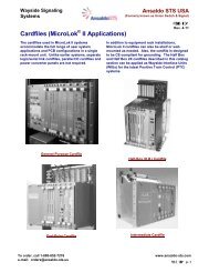
SM-6495 - Ansaldo STS
SM-6495 - Ansaldo STS
SM-6495 - Ansaldo STS

You also want an ePaper? Increase the reach of your titles
YUMPU automatically turns print PDFs into web optimized ePapers that Google loves.
Table of ContentsList of FiguresFigure 1-1 - Model 95 Gate Mechanism Basic Configurations ................................................................1-2Figure 1-2 - Original and Redesigned Power Down Modules..................................................................1-4Figure 1-3 - Model 95 Gate Mechanism Major Installation Parts.............................................................1-5Figure 2-1 - Completed Pedestrian Crossing Gate Arm Shield Installation.............................................2-5Figure 2-2 - Wiring Diagram for 12-Volt Systems – with Maintenance Switch ........................................2-9Figure 2-3 - Wiring Diagram for 12-Volt Systems – without Maintenance Switch .................................2-10Figure 2-4 - Wiring Diagram for 24-Volt Systems ..................................................................................2-11Figure 2-5 - Wiring Diagram for 3-Wire Control 12-Volt Systems..........................................................2-12Figure 2-6 - Wiring Diagram for Pedestrian Mechanism 12-Volt Systems withMaintenance Switch ..........................................................................................................2-13Figure 2-7 - Wiring Diagram for Pedestrian Mechanism 12-Volt Systems withoutMaintenance Switch ..........................................................................................................2-14Figure 2-8 - Torque Increase/Decrease Diagram ..................................................................................2-16Figure 2-9 - Number 1 Contact...............................................................................................................2-18Figure 3-1 - Hold Clear Device.................................................................................................................3-5Figure 3-2 - Installation Close-up ...........................................................................................................3-10Figure 3-3 - Location of the Power Down Module (Units ManufacturedBefore September 1, 2003) ...............................................................................................3-13Figure 3-4 - Proper Hardware Configuration on Terminal Posts 1C, 2C, and 3C..................................3-14Figure 3-5 - Location of Redesigned Power Down Module on Terminal Posts 1C, 2C, and 3C ..........3-14Figure 5-1 - Model 95 Gate Mechanism – Mechanical Assembly (Sheet 1 of 2)....................................5-4Figure 5-2 - Model 95 Gate Mechanism – Mechanical Assembly (Sheet 2 of 2)....................................5-5Figure 5-3 - Model 95 Pedestrian Gate Mechanism – Mechanical Assembly (Sheet 1 of 4) .................5-8Figure 5-4 - Model 95 Pedestrian Gate Mechanism – Mechanical Assembly (Sheet 2 of 4) .................5-9Figure 5-5 - Model 95 Pedestrian Gate Mechanism – Mechanical Assembly (Sheet 3 of 4) ................5-10Figure 5-6 - Model 95 Pedestrian Gate Mechanism – Mechanical Assembly (Sheet 4 of 4) ...............5-11Figure 5-7 - Model 95 Sidewalk Gate Mechanism – Mechanical Assembly (Sheet 1 of 3)(RH Shown – LH Available)...............................................................................................5-14Figure 5-8 - Model 95 Sidewalk Gate Mechanism – Mechanical Assembly (Sheet 2 of 3)(RH Shown – LH Available)...............................................................................................5-15Figure 5-9 - Model 95 Sidewalk Gate Mechanism – Mechanical Assembly (Sheet 3 of 3)(RH Shown – LH Available)...............................................................................................5-16Figure 5-10 - Model 95 Gate Mechanism Electrical Assembly with PN-150 Relay(12-Volt Systems) ..............................................................................................................5-19<strong>SM</strong> <strong>6495</strong>, Rev. 7, December 2008vii