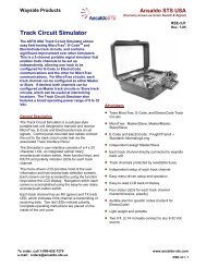
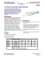
SM-6495 - Ansaldo STS
SM-6495 - Ansaldo STS
SM-6495 - Ansaldo STS

You also want an ePaper? Increase the reach of your titles
YUMPU automatically turns print PDFs into web optimized ePapers that Google loves.
General Maintenance and Troubleshooting2.5.3. Vertical Adjustment2.5.3.1. Vertical Adjustment Using Spring ScalesRaise the gate to the vertical position. Attach the spring scale at the specified distance (x) according toTable 2-1. This distance is measured from the mechanical output shaft and up the arm to where thespring scale is to be attached. Once scale is in place, release arm by loosening the gold nut on theterminal board. To adjust, loosen hardware and slide counterweights back and forth (this would be upand down if the arm were down).2.5.3.2. Vertical Adjustment Using Torque WrenchApply an appropriate torque wrench (J039000-0115 supplied in optional torque wrench kit X467000-03) to the motor shaft located in the lower-left corner of inside housing. Release arm by loosening thegold nut on the terminal board. To adjust, loosen hardware and slide counterweights back and forth(this would be up and down if the arm were down). Refer to Table 2-1 for appropriate measurements.2.6. Cam AdjustmentThe cams should be rotated so that the appropriate contacts are closed as indicated in Table 2-3. Use a3/16” T-handle Allen wrench provided with the gate mechanism to loosen one of the two cam screwsto be adjusted.Table 2-3 - Cam AdjustmentContact No. Closed (Degrees)* Function1 0-89 Motor Control Relay2 Not used for contact set.3** 46-93 Motor Down4 5-93 Bell5 0-5 Gate Down Indicator6 83-90 Flashing light* Ninety degrees-gate in vertical position.** When adjusting cams for the Sidewalk Gate Mechanism, it may be necessary to adjust the #3 cam in orderto properly drive the gate arm down.In a typical installation, the No. 1 cam will have to be rotated to determine precisely where the armrests in the vertical position. Ensure that the side-to side cam adjustment is centered with the contactassembly so that the contact assembly side walls do not touch the cams. Refer to Figure 2-9.After the cams are properly positioned, begin tightening the clamping screws until each cam begins tofit securely to the shaft. Turn the screw approximately 1-1/2 more turns to obtain torque. The HeelSpring force on the cams is 1-1/2 to 4 pounds on No. 1 spring, and 1/2 to 3 pounds on springs 3-6. Donot allow gaps between each cam half.<strong>SM</strong> <strong>6495</strong>, Rev. 7, December 2008 2-17