38Risø Energy Report 3<strong>Hydrogen</strong> conversion technologies5.3Indirect fuel cellDesulphurizationPrereformer(450-500°)“Tubular”reformer(600-900°)GascleaningFuelcellDirect fuel cellDesulphurizationPrereformerFuelcellFigure 13: SOFC system design. Fuel Processing Schemesmonoxide <strong>and</strong> carbon dioxide, which is then treated toremove carbon monoxide (CO). Allowable CO contentsare around 10 ppm for PEMFCs operating at 80°C <strong>and</strong>around 1% for PAFCs operating at 150-200°C.Methanol may also be used directly as a fuel, in whichcase PEMFCs are sometimes referred to as DMFCs (directmethanol fuel cells). NEC <strong>and</strong> Toshiba expect tocommercialise DMFCs in 2005, primarily for portableapplications such as laptop computers <strong>and</strong> personaldigital assistants (PDAs). Although their efficiency israther low, at around 30%, DMFCs are ideal replacementsfor batteries in portable equipment. Their energydensity is 4-5 times that of batteries, <strong>and</strong> they can berefuelled easily.High-temperature fuel cells (SOFCs) can run on fuelssuch as natural gas, biogas <strong>and</strong> methanol, thanks to theirability to reform hydrocarbons within the cell <strong>its</strong>elf.Reforming is an endothermic process, meaning that itabsorbs heat, <strong>and</strong> thus it can use waste heat createdduring the electricity generation process. Direct fuellingwith methane or methanol therefore increases both theelectrical efficiency <strong>and</strong> the total efficiency of the fuelcell compared to using hydrogen as the fuel.High-temperature fuel cells typically operate at about1,000°C, <strong>and</strong> the materials needed to withst<strong>and</strong> suchhigh temperatures make these fuel cells rather expensive.More recently, intermediate-temperature fuel cells operatingbelow 750°C promise to be more competitivebecause they are more durable as well as cheaper to build.Current R&D aims at developing SOFCs that can operateat 550-600°C.Direct SOFCs have the advantage that it is easy to removecarbon dioxide from the exhaust, because the gasstreams leaving the anode <strong>and</strong> cathode remain separate.The anode gas contains water, carbon dioxide <strong>and</strong>unburned hydrogen. One approach to exhaust cleanupuses a membrane to remove the hydrogen, which is thenrecycled to the inlet of the fuel cell. An alternative is tooxidise the hydrogen, using oxygen extracted fromatmospheric air by another type of membrane. In eachcase the result is a gas stream containing only water <strong>and</strong>carbon dioxide. The carbon dioxide can then be separatedby cooling to condense out the water.SOFC systemsIn a complete SOFC system (Figure 14), natural gas is firstpre-heated <strong>and</strong> desulphurised. It is then mixed with recycledanode off-gases, which provide steam <strong>and</strong> heat,before passing through an adiabatic pre-reformer. Thepre-reformer yields a mixture of methane, hydrogen,carbon monoxide <strong>and</strong> carbon dioxide. After passingthrough a final heat exchanger which increases <strong>its</strong>temperature to around 650°C, the fuel gas enters theanode compartment of the SOFC.Off-gas from the anode first heats the incoming fuel gas.Part of the off-gas stream is then mixed with the fuelentering the pre-reformer, while the rest goes to acatalytic incinerator. Heat from the incinerator exhaustis recovered in a further series of heat exchangers.On the cathode side, air is compressed in a blower <strong>and</strong>pre-heated in a heat exchanger, also to around 650°C.Off-gas from the cathode, consisting of depleted air, isfirst cooled against the incoming cathode air. Some ofthe off-gas then goes directly to heat recovery, while therest passes through the incinerator.Such a system has an electrical efficiency of nearly 56%<strong>and</strong> a total efficiency of 88%.PEMFC <strong>and</strong> PAFC systemsPEMFCs <strong>and</strong> PAFCs have attracted a lot of research effortin the last decade, especially for mobile applications,where they have the advantages of operating at temperaturesclose to ambient <strong>and</strong> fast start-up. PEMFCs will bethe preferred choice for devices such as uninterruptiblepower supplies (UPSs). The main disadvantage ofPEMFCs is their need for very pure hydrogen: state-ofthe-artPEMFCs cannot tolerate much more than 50 ppmof carbon monoxide in the anode feed without seriousdeterioration in performance. Water managementaround PEMFCs is complicated, <strong>and</strong> waste heat is onlyavailable at moderate temperatures.
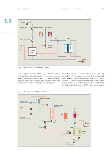
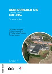
Risø Energy Report 3<strong>Hydrogen</strong> conversion technologies 395.3Flue gasE5Natural gas E1 Desulphurisation PrereformerWater for start upE6E2SOFCFlue GasE7CatalyticBurnerAnoderecycleAnodeCathodeE3AirBlowerFigure 14: Basic layout of an SOFC-based CHP system.In a complete PEMFC system (Figure 15) the feed ispreheated <strong>and</strong> desulphurised before steam is added.Steam reforming is carried out in a heat exchangereformer, using heat supplied by a gas-fired heater <strong>and</strong>also recovered from the reformer exhaust stream.The carbon monoxide content in the reformed gas is firstlowered to a few thous<strong>and</strong> ppm in a shift reactor, <strong>and</strong>then reduced to below 50 ppm in a preferential oxidation(PROX) reactor, which uses air to selectively oxidisecarbon monoxide to carbon dioxide. The exit gas fromthe PROX unit is cooled to 80°C before entering theFigure 15: Basic layout of a PEMFC-based CHP system.Natural gasDesulphurisationBFWHeat ExchangeReformerPROXFlue gasShiftBurnerAirBlowerPEMFCBFWAnodeCathodeCoolingWaterBFW