Setup of a Drift Tube Muon Tracker and Calibration of Muon ...
Setup of a Drift Tube Muon Tracker and Calibration of Muon ...
Setup of a Drift Tube Muon Tracker and Calibration of Muon ...

You also want an ePaper? Increase the reach of your titles
YUMPU automatically turns print PDFs into web optimized ePapers that Google loves.
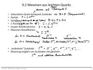
N [a.u.]∆ α (x)2200020000da0Entries 88028Mean −0.000274818000RMS 0.0933516000const 1393 ±4.814000σ 0.004899 ±0.00000012000lg 0.03125 ±0.000171000080006000∆ α0.0003038±0.0000997400020000−1.5 −1 −0.5 0 0.5 1 1.5∆αFigure 3.11: Angular alignment <strong>of</strong> the CMT. The plot shows the comparison <strong>of</strong> theHesse parameter α for a single reconstruction <strong>of</strong> tracks in each <strong>of</strong> the two modules inthe x−z-plane without any prior calibration. The distribution is fitted with a Voigtian(red). The mean value as well as the mean from the fit show a good angular alignment<strong>of</strong> the order <strong>of</strong> 0.3mrad.After the angular correction has been implemented, a possible translation <strong>of</strong> themodules is investigated. It is assumed that the position <strong>of</strong> module 1 is shifted by∆ξ in ξ <strong>and</strong> ∆ζ in ζ with respect to the true position. This shift is thus describedas a shift <strong>of</strong> the assumed coordinate system ξ ′ − ζ ′ <strong>of</strong> module 1 with:ξ ′ = ξ + ∆ξζ ′ = ζ + ∆ζ.Comparing the same muon track in both modules leads toξ cos α 0 + ζ sin α 0 − p 0 = ξ ′ cos α 1 + ζ ′ sin α 1 − p 1 ,<strong>and</strong> thus, assuming that α 0 <strong>and</strong> α 1 are equal, to∆p = ∆ξ cos α + ∆ζ sin α. (3.22)In reality α 0 <strong>and</strong> α 1 do not obtain the same value from the single fit. To obtaincomparable tracks, the reconstruction is redone for the second plane with a fixedparameter α = α 0 , leaving only one free parameter p 1 .∆p = p 1 − p 0 can now be determined from the single module reconstruction.Obtaining enough statistics allows to do a fit with free parameters ∆ξ <strong>and</strong> ∆ζ. The<strong>of</strong>fset values found using this method are subtracted from the initial wire coordinates<strong>and</strong> the new positions are again stored in TAlign. An exemplary fit for real data isshown in Fig. 3.15 in Section 3.8.2.3.6.2 Wire AlignmentOnce the relative position <strong>of</strong> the modules is determined, the alignment is continuedfor the single anode wires. The reconstructed data from the full 2D-planes <strong>of</strong> the42