Developed Operational Strategy - Low Level Waste Repository Ltd
Developed Operational Strategy - Low Level Waste Repository Ltd
Developed Operational Strategy - Low Level Waste Repository Ltd

Create successful ePaper yourself
Turn your PDF publications into a flip-book with our unique Google optimized e-Paper software.
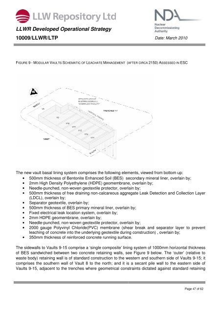
LLWR <strong>Developed</strong> <strong>Operational</strong> <strong>Strategy</strong>10009/LLWR/LTP Date: March 2010FIGURE 9 - MODULAR VAULTS SCHEMATIC OF LEACHATE MANAGEMENT (AFTER CIRCA 2150) ASSESSED IN ESCThe new vault basal lining system comprises the following elements, viewed from bottom up:• 500mm thickness of Bentonite Enhanced Soil (BES) secondary mineral liner, overlain by;• 2mm High Density Polyethylene (HDPE) geomembrane, overlain by;• Needle-punched, non-woven geotextile protector, overlain by;• 500mm thickness of free draining non-calcareous aggregate Leak Detection and Collection Layer(LDCL), overlain by;• Separator geotextile, overlain by;• 500mm thickness of BES primary mineral liner, overlain by;• Fixed electrical leak location system, overlain by;• 2mm HDPE geomembrane, overlain by;• Needle-punched, non-woven geotextile protector, overlain by;• 2000 gauge Polyvinyl Chloride(PVC) membrane (shear break and separator layer to preventleaching of concrete into the underlying geotextile during construction) , overlain by;• 350mm thickness of reinforced concrete running surface.The sidewalls to Vaults 9-15 comprise a ‘single composite’ lining system of 1000mm horizontal thicknessof BES sandwiched between two concrete retaining walls, see Figure 9 below. The ‘outer’ (relative towaste body) retaining wall is of standard construction to the western and southern side of Vaults 9-15; itcomprises the southern wall of Vault 8 to the north; and it is a secant pile wall to the eastern side ofVaults 9-15, adjacent to the trenches where geometrical constraints dictated against standard retainingPage 47 of 62