Baldwin TD and Hicks TW, Assessment Calculations for Human ...
Baldwin TD and Hicks TW, Assessment Calculations for Human ...
Baldwin TD and Hicks TW, Assessment Calculations for Human ...

Create successful ePaper yourself
Turn your PDF publications into a flip-book with our unique Google optimized e-Paper software.
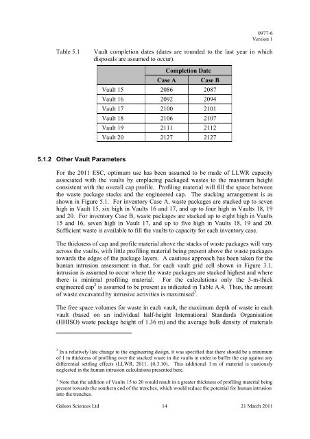
0977-6Version 1Table 5.1Vault completion dates (dates are rounded to the last year in whichdisposals are assumed to occur).Completion DateCase A Case BVault 15 2086 2087Vault 16 2092 2094Vault 17 2100 2101Vault 18 2106 2107Vault 19 2111 2112Vault 20 2127 21275.1.2 Other Vault ParametersFor the 2011 ESC, optimum use has been assumed to be made of LLWR capacityassociated with the vaults by emplacing packaged wastes to the maximum heightconsistent with the overall cap profile. Profiling material will fill the space betweenthe waste package stacks <strong>and</strong> the engineered cap. The stacking arrangement is asshown in Figure 5.1. For inventory Case A, waste packages are stacked up to sevenhigh in Vault 15, six high in Vaults 16 <strong>and</strong> 17, <strong>and</strong> up to four high in Vaults 18, 19<strong>and</strong> 20. For inventory Case B, waste packages are stacked up to eight high in Vaults15 <strong>and</strong> 16, seven high in Vault 17, <strong>and</strong> up to five high in Vaults 18, 19 <strong>and</strong> 20.Sufficient waste is available to fill the vaults to capacity <strong>for</strong> each inventory case.The thickness of cap <strong>and</strong> profile material above the stacks of waste packages will varyacross the vaults, with little profiling material being present above the waste packagestowards the edges of the package layers. A cautious approach has been taken <strong>for</strong> thehuman intrusion assessment in that, <strong>for</strong> each vault grid cell shown in Figure 3.1,intrusion is assumed to occur where the waste packages are stacked highest <strong>and</strong> wherethere is minimal profiling material. For the calculations only the 3-m-thickengineered cap 2 is assumed to be present as indicated in Table A.4. Thus, the amountof waste excavated by intrusive activities is maximised 3 .The free space volumes <strong>for</strong> waste in each vault, the maximum depth of waste in eachvault (based on an individual half-height International St<strong>and</strong>ards Organisation(HHISO) waste package height of 1.36 m) <strong>and</strong> the average bulk density of materials2 In a relatively late change to the engineering design, it was specified that there should be a minimumof 1 m thickness of profiling over the stacked waste in the vaults in order to buffer the cap against anydifferential settling effects (LLWR, 2011, §8.3.10). This additional 1 m of material is cautiouslyneglected in the human intrusion calculations presented here.3 Note that the addition of Vaults 15 to 20 would result in a greater thickness of profiling material beingpresent towards the southern end of the trenches, which would reduce the potential <strong>for</strong> human intrusioninto the trenches.Galson Sciences Ltd 14 21 March 2011