OPERATION MANUAL - Scintrex
OPERATION MANUAL - Scintrex
OPERATION MANUAL - Scintrex

You also want an ePaper? Increase the reach of your titles
YUMPU automatically turns print PDFs into web optimized ePapers that Google loves.
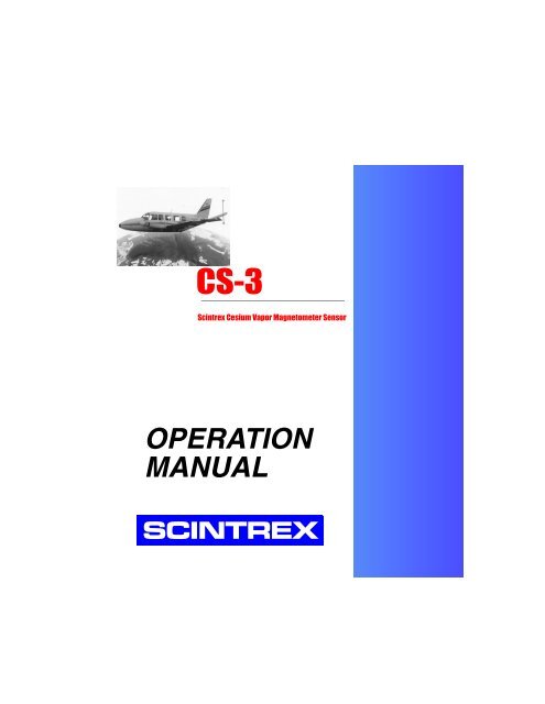
CS-3<strong>Scintrex</strong> Cesium Vapor Magnetometer Sensor<strong>OPERATION</strong><strong>MANUAL</strong>SCINTREX
Rev Description of change ECO Date of issue App1.0 Initial Release Feb 21, 2002 G.H.2.0 Additional information Nov 30, 2005 G.M.
CS-3<strong>Scintrex</strong> Cesium Vapor Magnetometer SensorOperation ManualCS-3 Manual - part # 762701 Revision 2.0
SCINTREX LIMITEDHEAD OFFICESCINTREX Limited222 Snidercroft RoadUnit #1Concord, OntarioCanada, L4K 2K1tel: +1 905 669 2280fax: +1 905 669 6403e-mail:scintrex@scintrexltd.comWorld-wide web: http://www.scintrexltd.comCopyright © SCINTREX Limited 2005. All rights reserved.No part of this publication may be reproduced, stored in a retrieval system ortransmitted, in any form, or by any means, electronic, mechanical,photo-copying, recording, or otherwise, without prior consent fromSCINTREX Limited.Document Part No. 762701, Revision 2.0Printed and bound in CanadaCS-3 Manual - part # 762701 Revision 2.0
ForewordGetting StartedAbout this manual . . . . . . . . . . . . . . . . . . . . . . . . . . . . . . . . . . . . . . . . . . . . . . . . . . . . . 1-1Page Numbering . . . . . . . . . . . . . . . . . . . . . . . . . . . . . . . . . . . . . . . . . . . . . . . . . . . 1-1Type Styles . . . . . . . . . . . . . . . . . . . . . . . . . . . . . . . . . . . . . . . . . . . . . . . . . . . . . . . 1-2Chapter Layout . . . . . . . . . . . . . . . . . . . . . . . . . . . . . . . . . . . . . . . . . . . . . . . . . . . . 1-3Symbols . . . . . . . . . . . . . . . . . . . . . . . . . . . . . . . . . . . . . . . . . . . . . . . . . . . . . . . . . 1-4Understanding Instrument Basics . . . . . . . . . . . . . . . . . . . . . . . . . . . . . . . . . . . . . . . . 1-5Sensor Head . . . . . . . . . . . . . . . . . . . . . . . . . . . . . . . . . . . . . . . . . . . . . . . . . . . . . . 1-5Sensor Electronics . . . . . . . . . . . . . . . . . . . . . . . . . . . . . . . . . . . . . . . . . . . . . . . . . 1-7Old version . . . . . . . . . . . . . . . . . . . . . . . . . . . . . . . . . . . . . . . . . . . . . . . . . . . . . . . 1-9New 2nd version Draft . . . . . . . . . . . . . . . . . . . . . . . . . . . . . . . . . . . . . . . . . . . . . . . . . . . . . . 1-9Operating the CS-3 in the FieldSetting Up the CS-3 . . . . . . . . . . . . . . . . . . . . . . . . . . . . . . . . . . . . . . . . . . . . . . . . . . . . 2-2Mounting the CS-3 . . . . . . . . . . . . . . . . . . . . . . . . . . . . . . . . . . . . . . . . . . . . . . . . . 2-32Powering Up . . . . . . . . . . . . . . . . . . . . . . . . . . . . . . . . . . . . . . . . . . . . . . . . . . . . . . 2-4Obtaining the Larmor Signal . . . . . . . . . . . . . . . . . . . . . . . . . . . . . . . . . . . . . . . . . . . . . 2-52ndSetting the Operating Hemisphere . . . . . . . . . . . . . . . . . . . . . . . . . . . . . . . . . . . . . . . . 2-7Operating in the Presence of Spurious Magnetic Fields . . . . . . . . . . . . . . . . . . . . . . 2-9Orienting Your CS-3Understanding the Active Zone of the CS-3 . . . . . . . . . . . . . . . . . . . . . . . . . . . . . . 3-2Using a Strapped Down CS-3 for Surveys . . . . . . . . . . . . . . . . . . . . . . . . . . . . . . . 3-7Calculating the Tumble Angle . . . . . . . . . . . . . . . . . . . . . . . . . . . . . . . . . . . . . . . . . 3-7Recommended Survey Orientations . . . . . . . . . . . . . . . . . . . . . . . . . . . . . . . . . . . 3-18Comparison with the Locked Oscillator. . . . . . . . . . . . . . . . . . . . . . . . . . . . . . . . . 3-20Table of ContentsMaintaining Your CS-3 and Trouble-shootingTrouble-shooting . . . . . . . . . . . . . . . . . . . . . . . . . . . . . . . . . . . . . . . . . . . . . . . . . . . . . . 4-2Reference InformationCS-3 Technical Specifications. . . . . . . . . . . . . . . . . . . . . . . . . . . . . . . . . . . . . . . . . . . . 5-1Instrument Parts List . . . . . . . . . . . . . . . . . . . . . . . . . . . . . . . . . . . . . . . . . . . . . . . . . . . 5-3CS-3 Standard Accessories . . . . . . . . . . . . . . . . . . . . . . . . . . . . . . . . . . . . . . . . . . 5-3Warranty and Repair. . . . . . . . . . . . . . . . . . . . . . . . . . . . . . . . . . . . . . . . . . . . . . . . . . . . 5-3Warranty . . . . . . . . . . . . . . . . . . . . . . . . . . . . . . . . . . . . . . . . . . . . . . . . . . . . . . . . . 5-3Repair . . . . . . . . . . . . . . . . . . . . . . . . . . . . . . . . . . . . . . . . . . . . . . . . . . . . . . . . . . . 5-4CS-3 Manual - part # 762701 Revision 2.0v
Shipping Instructions . . . . . . . . . . . . . . . . . . . . . . . . . . . . . . . . . . . . . . . . . . . . . . . . 5-4Appendix A: Theory of OperationSystem Overview. . . . . . . . . . . . . . . . . . . . . . . . . . . . . . . . . . . . . . . . . . . . . . . . . . . A-1Appendix B: CS-3 Block DiagramviCS-3 Manual - part # 762701 Revision 2.0
ForewordForewordThe CS-3 is an optically pumped cesium vapor magnetometer sensor used forscalar measurement of the Earth's magnetic field. As shown below, the CS-3sensor consists of a sensor head with cable and sensor electronics.Figure 1: CS-3 Magnetometer SensorThe system excels in a variety of applications (ex. airborne, satellite, marineand ground magnetometry or gradiometry, base station magnetometry andferrous ordnance location) due to its:• high sensitivity• high cycling rates• excellent gradient tolerance• continuous output• automatic hemisphere switchingviiCS-3 Manual - part # 762701 Revision 2.0
• fast response• low susceptibility to the electromagnetic interferenceMagnetic field measurements performed by the CS-3 is based on quantummechanics principles, and the phenomena of optical pumping andself-oscillation. When properly oriented in relation to the ambient magneticfield, cesium vapor in the sensor oscillates continuously by itself without anyassistance. The frequency of oscillation (defined as the Larmor frequency) isproportional to the ambient magnetic field.The sensor outputs a signal at the Larmor frequency which is normallyprocessed by an external magnetometer processor linked to the system. Themagnetometer processor converts the Larmor frequency into digital magneticfield readings and presents them for display and recording. Modern magneticprocessors have a resolution of 0.001 nT and read 10 times each second orfaster.In summary, the CS-3 offers distinct and substantial benefits in measurementof magnetic fields due to the principles of both optical pumping andself-oscillation. These advantages are described in the next two sections.Advantages of Optical PumpingThese benefits are shared by all well designed optically pumpedmagnetometers regardless of which atoms (cesium, rubidium, potassium orhelium) are being pumped, and regardless which of two principles ofoperation is utilized (self oscillation, or locked oscillation).High SensitivityDue to the narrow resonant linewidth and good signal to noise ratio thesensitivity of optically pumped magnetometers is in the range of few pT(1pT=0.001nT) in the measuring bandwidth of 1Hz. In contrast to the protonprecession magnetometers, the sensitivity does not deteriorate as themeasured ambient field decreases.Continuous SignalThe operation of the optically pumped magnetometers is not cyclic. Highlysensitive readings could be obtained at the high repetition rate.viiiCS-3 Manual - part # 762701 Revision 2.0
High Gradient ToleranceAbsorption cells of the optically pumped magnetometers in which thedetection of the ambient field is taking place are normally much smaller thanthe sensors of proton precession (including Overhauser) magnetometers.Consequently, the field gradients over the sensor volume are much smallerand the proper operation of the magnetometer is much less affected, e.g. thevolume of the CS-3 absorption cell is only 0.006 liters.Low Radiated Electromagnetic InterferenceForewordSensors of the optically pumped magnetometers radiate low disturbing EMfields. The H 1 field is the order of 10 nT. The RF field for the lamp excitationis well confined and of the high frequency - around 165 MHz for the CS-3.2nd DraftInsensitivity to Motion Induced Doppler EffectsIrregular motion of the platform carrying the sensor modulates (adds to) theprecession frequency and introduces noise into the measurements of the2magnetic field.Proton 2ndprecession (including Overhauser) magnetometers are affected to amuch greater degree by motion noise due to much lower gyromagneticconstant, e.g. in the ambient magnetic field of 50,000nT the Larmorfrequency of the CS-3 is 175,000Hz, which is 82 times larger than 2100Hz,the precession frequency of the proton magnetometer.Advantages of Self OscillationUse of the self-oscillating principle of operation results in the followingadditional benefits not available from optically pumped magnetometers usinglocked oscillator principle of operation:Fast Start-upIf the sensor head is properly oriented inside its active operating zone, theCS-3 will start oscillating shortly after it is turned on. The warm-up time isdetermined by the time required for the electronically controlled heaters tobring the absorption cell and the cesium lamp to the proper operatingtemperature.ixCS-3 Manual - part # 762701 Revision 2.0
The warm-up is over in few minutes after a cold start. However, if theoperating temperature is already established, it takes only few millisecondsfor the magnetometer to start oscillating after a turn on or after an orientationchange from a dead zone into the active zone.In contrast, a locked oscillator magnetometer invariably contains a voltagecontrolled oscillator (VCO), whose frequency in normal operation is forced(locked) by the control electronics to follow the resonant Larmor frequency.However, at every start-up, cold or warm, before the locking is acquired, theVCO frequency has to be swept relatively slowly until it comes close enoughto the Larmor frequency. Then the locking takes place and the magnetometerbecomes operational.Note that the Larmor frequency is known beforehand only coarsely andconsequently this search process takes several seconds. The same searchprocedure takes place if the lock is lost because of a fast field change or adisturbing AC magnetic field.Fast Response and TrackingThe response of a self-oscillating magnetometer to the magnetic fieldchanges is extremely fast. It has been experimentally determined that theLarmor frequency precisely changed in response to the step changes ofseveral thousand nT within a Larmor period. Equally, the magnetometerfollowed sinusoidal field changes of the amplitude of hundreds nT at the rateof several kHz without appreciable lag in response.In contrast, the rate of ambient field change, which a locked oscillatormagnetometer could follow without losing lock, is much smaller. In addition,spurious fields, either AC (50-400Hz) or pulsed, in the range of severalhundred nT cause the magnetometer to lose lock.Low Susceptibility to Electromagnetic FieldsThe susceptibility to spurious EM fields depends very much on the principleof operation. Most widely encountered spurious fields originate from thepower lines and the airborne geophysical EM systems, and are in thefrequency range of 50Hz to several thousand Hz. In general, thesusceptibility increases greatly as the frequency of the interfering fieldapproaches the operating (Larmor, proton precession) frequency.Proton precession magnetometers (including Overhauser) have lowsusceptibility for two reasons:• they use induction coils to detected proton precessionxCS-3 Manual - part # 762701 Revision 2.0
• the interfering EM field are normally at the frequencies close to the protonprecession frequency.Neither of above liabilities apply for optically pumped magnetometersbecause:• signal detection is optical• the interfering frequencies are normally far from the Larmor frequency.In addition, the susceptibility of the self-oscillating magnetometer is low,because its feedback loop is very simple and fast, allowing it to respond withlittle lag to the fast changing fields.In contrast, the locked oscillator response is much slower because its controlloop frequency bandwidth is limited to few hundred Hz. Furthermore, the2nd Draftfeedback control is achieved by monitoring a modulating signal, whichfrequency is in the range of one hundred Hz, and which detection could bereadily upset by the interfering EM fields.For either of above reasons, the locked oscillator may lose lock and becometemporary non-functional for few seconds in presence of a spurious EM field.2Superior Worldwide Orienting Capabilities2ndThe analysis presented in Chapter 3, “Orienting Your CS-3” proves that,contrary to the widely accepted belief, a well designed self-oscillatingmagnetometer is as easy to orient as the locked oscillator. Even moreimportant, it offers wider safety margins to the boundaries of operating zone,than the locked oscillator.ForewordxiCS-3 Manual - part # 762701 Revision 2.0
xiiCS-3 Manual - part # 762701 Revision 2.0
1 GettingStartedStartupAbout this manualPage NumberingThe numbering scheme used consists of two parts: the chapter number andpage number. For example, 3-1 would refer to chapter 3, page 1.For your convenience, each chapter has a thumb-tab on the right-hand sideallowing you to quickly locate a chapter of interest. The thumb-tabs arearranged in descending order, with Chapter 1 always starting at the top.1-1CS-3 Manual - part # 762701 Revision 2.0
Getting StartedType StylesThe following typeface conventions will be used throughout the manual.ConventionBold ItalicItalicALL CAPSUseIndicates an action to be takenDenotes a new term being introducedDenotes the name of a screen, key or mode (function)1- 2CS-3 Manual - part # 762701 Revision 2.0
About this manualChapter LayoutThis manual is divided into six chapters and four appendices with theinformation flow detailed in the following table.ChapterDescription1. Getting Started Gives an overview of the manual and describes theinstrument’s components.2. Operations Tells how to set up your CS-3 for a survey, including howto mount and operate the system.3.Orientation Gives a detailed theoretical and practical review of theconsiderations for orienting the instrument to obtain bestresults.4. Maintenance Gives a brief overview of how to maintain andtrouble-shoot your system.5.Reference Contains the technical specifications, instrument partslist and warranty information.A.Theory ofOperationExplains the scientific and instrumentation theory for theCS-3 instrument.Startup1-3CS-3 Manual - part #762701 Revision 2.0
Getting StartedSymbolsThe following symbols will be used to highlight specific sections of textthroughout the manual.SymbolMeaningWarning:Denotes an important point concerning safetyImportant:Indicates a important topic, particular attention should bepaid to this sectionNote:Denotes a point of interest, or information you should readTip:Denotes an interesting hint for smoother operationQuestion:Indicates a relevant question concerning an importanttopic1- 4CS-3 Manual - part # 762701 Revision 2.0
Understanding Instrument BasicsUnderstanding Instrument BasicsThe CS-3 Magnetometer Sensor consists of a sensor head and sensorelectronics that are interconnected by a cable. This section providesschematics and descriptions for each of these components and theirsubsystems.Sensor HeadThe sensor head houses electro-optical detection system. All the parts of thesensor head, including the outside plastic housing, are made of carefullyscreened nonmagnetic materials. The following figure shows a schematic ofthe sensor head.Startup3Figure 2 - Schematic of the sensor head1-5CS-3 Manual - part #762701 Revision 2.0
Getting StartedImportant:To minimize the static magnetic interference fromthe electronic components which are slightlymagnetic, the sensor head should be kept away fromthe electronics assembly by the full cable length.The actual measurement of the ambient magnetic field takes place inside theabsorption cell which has diameter 22mm, and the length 25mm. Theposition of the cell's centre is marked by a narrow groove, machined on theoutside of the plastic cylindrical housing. The adjacent wider grove isprovided to facilitate secure grip for the mounting clamps.The interconnecting cable exits at the right angle on the top end of the sensorhead. For properly orienting the sensor head as described in Chapter 3,“Orienting Your CS-3”, it is important to know the direction of the opticalaxis. In Figure 1 on page vii, the direction of the optical axis is depicted inrelation to the outside mechanical features of the sensor head.The sensor head housing provides an air/water tight enclosure for the sensorcomponents, and it should not be opened. In addition, critical opticalcomponents inside the sensor head are carefully aligned in order to minimizethe orientation errors, and opening the sensor head by unqualified peoplemay upset the alignment.1- 6CS-3 Manual - part # 762701 Revision 2.0
Understanding Instrument BasicsSensor ElectronicsThe sensor electronics are housed in a cylindrical container as shown in thefollowing schematic.CS-3 ELECTRONIC HOUSINGStartupFigure 3 - Schematic of the electronics housingThe electronics consist of three major subsystems:• Larmor amplifier• Lamp and absorption cell heaters• RF lamp exciterThe RF exciter generates few watts of RF power at the frequency of about165MHz. In order to keep the radiated electromagnetic interference low, theexciter is located inside a metallic enclosure. In addition, all the sensorelectronic systems are enclosed inside a cylindrical, metal box.Electronic HousingInternally, the sensor electronic housing is connected to the negative line ofthe input supply voltage. If the negative side of the power supply, whichprovides the power for the CS-3, is grounded to the frame of the vehicle, andif the electronic box of the CS-3 makes an electrical contact to the sameframe, then the return current could flow partially through the frame insteadof being confined to the return line inside the supply cable.1-7CS-3 Manual - part #762701 Revision 2.0
Getting StartedThe stray magnetic field created by this current could corrupt themeasurement of the ambient field. To prevent that happening, the outside ofthe electronics box is covered with a thin, plastic insulating sleeve.Important:Please, make sure that this plastic sleeve is notdamaged to such an extent that the metal part of theCS-3 electronics housing is making contact to ametal part of the airplane or vehicle frame.The sensor head connector is mounted on one side panel of the electronicbox. On the opposite side, following components are mounted on the controlpanel, see Figure 4.Hemisphere Control SwitchThe hemisphere control switch is a four-position rotary switch as shownbelow. Please note that depending upon the version of your Cs-3, you willhave either version.OLD VERSIONNEW VERSIONFigure 4 - Schematic of the hemisphere control switch1- 8CS-3 Manual - part # 762701 Revision 2.0
Understanding Instrument BasicsOld versionThe swich settings perform the following functions:N - Manually sets the CS-3 to operate in northern operating hemisphere.S - Manually sets the CS-3 to operate in southern operating hemisphere.L - Local setting allows the operation of the CS-3 to be controlled by theTTL voltage level at the pin D of the four pin connector (pin A is ground):open circuited or high level voltage for operation in southern hemisphere,low level voltage or short connected to pin A for operation in northernoperating hemisphere.R - (JP3 - OFF, JP2 - ON). Remote setting allows the operation of the CS-3to be controlled remotely by superimposing on the supply voltage an 80Hzsine signal. In the absence of the signal, the CS-3 is set to operate in thenorthern hemisphere.R - (JP3 - ON, JP2 - OFF). Automatic hemisphere switch.StartupNote:JP2 and JP3 refer to jumpers on the Larmor board.New versionThe swich settings perform the following functions:N - Manually sets the CS-3 to operate in northern operating hemisphere.S - Manually sets the CS-3 to operate in southern operating hemisphere.R - Remote setting allows the operation of the CS-3 to be controlled by theTTL voltage level at the pin D of the four pin connector (pin A is ground):open circuited or high level voltage for operation in southern hemisphere,low level voltage or short connected to pin A for operation in northernoperating hemisphere.A - Automatic hemisphere switch.I/O ConnectorFour pins of the I/O connector carry following signals:1-9CS-3 Manual - part #762701 Revision 2.0
Getting StartedA - ground levelB - positive input of the supply voltage +24 to 35 V; this input is connected inparallel to the centre pin of the coaxial TNC power connector on the samepanelC - Larmor output signal, TTL compatible square voltage signal at LarmorfrequencyD - TTL compatible input: high level or open for operation in the southernoperating hemisphere, low level or connected to pin A for operation in thenorthern hemisphere. This input is effective only if the Hemisphere Controlswitch is in the Remote (R) position.1-10CS-3 Manual - part # 762701 Revision 2.0
2 Operating theCS-3 in theFieldBy now you have familiarized yourself with your CS-3. This chapter reviewsthe basic steps required to carry out a survey. They include the following:• setting up the CS-3• mounting the CS-3• powering up• obtaining the Larmor frequency• setting the operating hemisphere• operating in the presence of spurious magnetic fieldsOperations2-1CS-3 Manual - part # 762701 Revision 2.0
Operating the CS-3 in the FieldSetting Up the CS-3The basic procedure for setting up the CS-3 is as follows:• mount the sensor in the vehicle according to the mounting instructions (seebelow)• connect the sensor head to the electronics via the supplied cableNote:To minimize the static magnetic interference fromthe electronic components which are slightlymagnetic, the sensor head should be kept away fromthe electronics assembly by the full cable length. Ifthe electronics is kept at 3 meters away from thesensor head, its magnetic signature is less than0.1nT.• make sure that you have between 24 and 35V of power to the device• connect the CS-3 to the power connector (i.e. link to your power supply, dataacquisition unit or coupler)• turn on the powerWarning:BEFORE THE POWER IS APPLIED TO THECS-3, THE CONNECTOR AT THE END OF THESENSOR HEAD CABLE HAS TO BECONNECTED TO THE MATING SOCKETLOCATED AT THE ELECTRONICS BOX SIDEPLATE. THIS CONNECTOR SHOULD NEVERBE DISCONNECTED WHILE THE POWER ISAPPLIED TO THE CS-3. DOING SO WILLRESULT IN SERIOUS DAMAGE TO THE RFEXCITER AND WILL VOID THE WARRANTY.• let the unit warm up for a designated warm up period to enable the lamp andheaters to stabilize (i.e. stabilize the optics)The remainder of this chapter provides more details that will help you withinstallation and start-up.2-2CS-3 Manual - part # 762701Revision 2.0
Setting Up the CS-3Mounting the CS-3The quality of data depends greatly on the quality of the installation. Ouradvice is to obtain the services of a highly skilled systems engineer for theinstallation of all magnetometer sensors and associated surveyinstrumentation. There are numerous factors related to aircraft,instrumentation and custom modifications that may be required to achieve asuccessful installation.In general, when mounting a high sensitivity sensor such as the CS-3, youshould consider the following guidelines:• Secure the sensor so that it is rigid during aircraft motion. The use of aproper gimbal is highly recommended. The gimbal makes changing theorientation easier and also provides a secure base for operating the sensor.• Keep the sensor as far as possible away from moving surfaces or magneticinducing objects.• Screen all hardware used in proximity of the sensor for ferrouscontamination.• Minimize the amount of conductive hardware, such as brass screws andaluminum, as they will introduce a secondary field when they are in motionthrough the earth field.• Although the sensor electronics have a minimal magnetic signature, keep theelectronics as far away as possible from the sensor.• Always ensure that the cable between the sensor and electronics is physicallysecured.• Do not coil the cable to take up slack. If necessary, all slack should be at thepreamplifier electronics end of the installation.• Always ensure that there is adequate ventilation at both the sensor head andthe preamplifier electronics. This is especially critical when operating in hotclimates.• Keep the sensor away from direct exposure to weather elements and keep itclean from debris.• Ensure that there is adequate static discharge available along the surroundingsurfaces of the aircraft installation. In dry conditions, static will build alongthe flying surfaces and create noticeable “pop” noise in the data duringdischarges.• Do not place secondary sensors, such as a fluxgate magnetometer, in veryclose proximity to the cesium sensor.Operations2-3CS-3 Manual - part #762701 Revision 2.0
Operating the CS-3 in the FieldPowering UpThe power for the CS-3 should be supplied from a DC supply 24-35V, 2Aminimum supply capability. The power can be connected either througheither:• the coaxial TNC connector by a 50 ohm coaxial cable (centre pin positivewire)• the four pin I/O connector, on pins B (positive wire) and A (negative wire).The sensor electronics is protected from an accidental polarity reversal onboth power inputs.The green light on the side panel indicates that the power is applied to thesensor electronics. Initially, after the power-up, the red indicator light glowsfor a short while to indicate that the cesium lamp located inside the sensorhas not yet reached proper operating level.Normally, this indicator light will go off completely indicating that thecesium lamp is radiating sufficient light. At 25°C it takes normally only fewseconds for this light to go off. At a low ambient temperature, it may takelonger for the lamp exciter to warm up and for the lamp to start to operateproperly.At the beginning of the cold start-up, the power supply current will behighest, approximately 1.5A, as the cell and the lamp heater are operating atthe full output capacity. As the cell and the lamp are approaching the requiredstabilized operating temperature, the supply current will decrease and it willreach steady level which is ambient temperature dependent.At the 20°C the supply current will be approx. 0.5A, at -40°C it is approx.0.7A. The warm-up time is less than 5 minutes at 20°C, increasing to lessthan 15 minutes at -40°C.2-4CS-3 Manual - part # 762701Revision 2.0
Obtaining the Larmor SignalObtaining the Larmor SignalIf the sensor head is properly oriented inside its active operating zone, asdescribed in Chapter 3, “Orienting Your CS-3”, the CS-3 will start oscillatingshortly after it is turned on, as soon as the absorption cell and the cesiumlamp reach the operating temperature.Note:If the operating temperature is already established, ittakes only few milliseconds for the magnetometer tostart oscillating after a warm power-up or after anorientation change from a dead zone into the activezone.The frequency of oscillation is called the Larmor frequency. The Larmorfrequency is proportional to the magnitude of the ambient magnetic field.The constant of proportionality, which relates the magnitude of the ambientmagnetic field to the Larmor frequency, is known as the gyromagneticconstant and for the cesium 133 it equals 3.498577Hz/nT.The amplitude of the output signal of the CS-3 is kept nearly constant(+/-15% variation is due to the transformer frequency characteristic) byelectronic means for magnetometer orientations inside the active zone, inspite of:• the amplitude changes of the light modulation (original Larmor signal) withthe magnetometer orientation and• the amplitude versus frequency dependence of the Larmor amplifierelectronics.OperationsOutput SignalsThe output signals at the Larmor frequency are available in two formats:• square wave signal with TTL/CMOS logical levels is available at the I/Oconnector, pin C, with the ground at pin A. Fast transitions of the squarewave make this output much less susceptible than the sinewave output to thesystem noises like ground line noise. The output driving capability of thisoutput restricts the maximum cable length of the RG-58 coaxial cable to 8meters. An external line driver is required if the signal is to be transmittedover the longer distance.2-5CS-3 Manual - part #762701 Revision 2.0
Operating the CS-3 in the Field• sinewave Larmor signal is transformer coupled inside the sensor electronicsbox on to the D.C. power supply line. This is done in a similar way as in theolder models of Varian and <strong>Scintrex</strong> cesium vapor magnetometers. The onlydifference that the output amplitude of the CS-3 is electronically stabilized tobe independent of the sensor orientation or slightly dependent of the Larmorfrequency over the range of 50-350kHz. This additional feature will preventthe sensitivity of the magnetometer to deteriorate more than necessary inpresence of the power supply noise. The power supply noise affects more thesignal with the lower amplitude.Couplers, Processors and Power SuppliesIn older magnetometers the output amplitude was varying as much as 10:1.The CS-3 magnetometer could easily replace, as far as the power and signalconditioning is concerned, the older models without any changes to theexisting equipment such as sensor couplers, magnetometer processors, powersupplies.The only incompatibility is in the control of the operating hemisphere, as itwill be explained in the next section. The Larmor signal coupled on thecoaxial power cable could be transmitted to the processor (decoupler) overthe distance of up 100 meters before it is decoupled by a transformer.Many of modern magnetometer processors, such as <strong>Scintrex</strong> MEP series ofprocessors, incorporate the power and signal conditioning circuits such as theregulated power supply and the sensor decoupler. One has to just connect thecoaxial power cable to the appropriate power output connector and theinstallation is complete. The supply current is measured and displayed, aswell.For more detailed information, please, refer to the specific processoroperating manual. The MEP series of processors obsoletes the oldergeneration of <strong>Scintrex</strong> self standing sensor couplers such as VIW2340A1 orVIW2340D4, but they still could be used in existing installations to decouplethe Larmor signal from the CS-3.2-6CS-3 Manual - part # 762701Revision 2.0
Setting the Operating HemisphereSetting the Operating HemisphereIt has been briefly explained why the operation of the CS-3 is divided in twooperating hemispheres in Chapter 1, “Getting Started with the CS-3”.Chapter 3, “Orienting Your CS-3” defines the operating hemispheres in moredetail, and provides instructions on how to orient the sensor head.Here, we explain how the operator can control the setting of the operatinghemisphere. The Hemisphere Control switch is used to select the mode ofcontrol. FOUR modes of control of the operating hemisphere setting areavailable:Manual ControlTwo positions of the Hemisphere Control switch are used for the manualcontrol:• in position "N" the CS-3 is set manually to operate in the northern operatinghemisphere.• in position "S" the CS-3 is set manually to operate in the southern operatinghemisphere.Electronic Control "R"OperationsIn the position "R" of the Hemisphere switch, the setting of the operatinghemisphere is actuated by the TTL compatible control voltage level at the pinD of the four pin I/O connector: open circuited or high level voltage forsetting the operation in southern hemisphere, low level voltage or shortconnection to the pin A for operation in northern operating hemisphere.The control voltage could be supplied to the connector pins D and A througha coaxial cable or a pair of twisted wires. The length of the cable or the wiresis not critical, as the control voltage is D.C. signal.“A” - Automatic Hemisphere SwitchIn the position “A” of the hemisphere switch, the CS-3 is operating inautomatic hemisphere switching mode.2-7CS-3 Manual - part #762701 Revision 2.0
Operating the CS-3 in the FieldSummaryIf the CS-3 is properly oriented inside the active zone, defined by equations(1) and (2) in Chapter 3, “Orienting Your CS-3”, and the operatinghemisphere is not set properly either of following will happen:• There will be no Larmor signal at the output. By setting the operation to theproper operating hemisphere, the Larmor signal will appear.• There will be signal at the output, but not at the Larmor frequency. The falsemagnetic field reading will be higher than the true reading, obtained whenthe operating hemisphere setting is correct (about 60nT higher if the ambientfield is 60,000nT). In addition, it will be much noisier.The reason for this is the existence of another resonant line, smaller inamplitude and opposite in phase from the desired resonant signal. Theself-oscillation based on this signal can take place if the operatinghemisphere is wrongly selected. By setting the operation to the properoperating hemisphere, the true, lower value and less noisier, magnetic fieldreading will be obtained.The described alternative modes of controlling the operating hemisphere ofthe CS-3 are incompatible with the optional electronic control used in oldermodels of Varian and <strong>Scintrex</strong> magnetometers.The reversing of the magnetometer power supply polarity, used in these oldermagnetometer models, had certain disadvantages and it was abandoned in theCS-3. It is not difficult to change the existing installations by rewiring theswitch used for the power supply reversal and to make it perform levelcontrol required by the electronic control mode "R", as described in thissection, or by automatic hemisphere switching.2-8CS-3 Manual - part # 762701Revision 2.0
Operating in the Presence of Spurious Magnetic FieldsOperating in the Presence ofSpurious Magnetic FieldsIt is not uncommon for magnetometers to be required to operate in presenceof higher magnitude (over 50nT) alternating magnetic fields. These fields arepresent close to the power lines, and in the survey airplanes equipped withEM transmitters.Before it is explained how the AC magnetic fields could upset the operationof a real magnetometer, specifically the CS-3, it is worth mentioning thatreadings of an ideal scalar magnetometer can be affected by an AC field. Thealternating field adds vectorially to the D.C. field to be measured.Due to the nonlinearity of the vector addition (squaring and taking squareroot) one observes an error. If the AC field b(coswt) has a componentb p (coswt) at right angle to the D.C. field B, one measures effectively themean value equal to B e =B[1+(b p /2B)2].For gaining more insight, the effective mean value is tabled for B=50000nTand several values of b p :Operationsb p [nT] 0 100 200 500 10000B e [nT] 50000.00 50000.05 50000.20 50001.25 50005.00If the magnitude or the orientation of the AC field changes, the effectivemean value will change as well.The CS-3, as explained the “Foreword” of this manual, is much less sensitive tothe spurious AC fields than either the proton precession (includingOverhauser) magnetometers or the locked oscillator optically pumpedmagnetometers.In the CS-3, the spurious AC field affects the precession of the magneticmoment similarly to the H 1 field. More information is provided in AppendixA, “Theory of Operation”. If the AC field is large enough it will provokeconsiderable light modulation at its own frequency. Further away thespurious field frequency is from the Larmor frequency larger magnitude isrequired to cause trouble. If this light modulation becomes comparable inamplitude to the normal modulation induced by the feedback field H 1 , theoperation of the CS-3 may be seriously affected.2-9CS-3 Manual - part #762701 Revision 2.0
Operating the CS-3 in the FieldIt is important to mention that the disturbing effect is reduced, if the directionof the spurious AC field is perpendicular to the sensor optical axis. It hasbeen experimentally determined that in this case the tested magnetometeroperated satisfactory in presence of the disturbing field with magnitude3500nT peak at the frequency 3kHz.The operating range of the tumble angle, in the plane perpendicular to thedirection of the spurious field, was reduced from 10°-85° (without the ACfield) to 25°-65° (with the AC field).2-10CS-3 Manual - part # 762701 Revision 2.0
3 OrientingYour CS-3An ideal magnetometer placed in a constant field should produce a constantfrequency. A real optically pumped magnetometer, regardless of whichelement it uses for its operation (cesium, rubidium, potassium or helium), andregardless of which principle of operation it employs (self oscillating, lockedoscillator), produces a frequency which varies because:• the unavoidable sensor noise makes the frequency jitter around the correctfrequency• the output frequency is somewhat dependent on the magnetometerorientationThe later dependency gives rise to the so-called heading error. Both, themagnetometer noise and the heading error, are low due to proper design andcareful alignment of the magnetometer. Precautions should be taken that theyare sustained low by properly orienting the magnetometer sensor inside theoperating active zone.The purpose of this section is to recommend how to achieve the properorientation without restricting established survey practices.Orientation3-1CS-3 Manual - part # 762701 Revision 2.0
Orienting Your CS-3Understanding the Active Zone of the CS-3The sensor head assembly has a so called optical axis. The angle between thepositive direction of the optical axis and the direction of the magnetic field,H o , is called the tumble angle, q.As explained in Appendix A, “Theory of Operation”, there is no Larmorsignal generated in a self-oscillating magnetometer such as the CS-3 ifthe optical axis is parallel to the magnetic field (the polar orientation,q=0° or q=180°) or perpendicular to the field (the equatorial orientation,q=90°).The optical signal amplitude increases quite rapidly outside those twoorientations, and it has a broad maximum around q=40° or q=140°.Note:The Larmor signal amplitude generated inside thesensor head is not to be confused with the signaloutput of the CS-3 available either inside theelectronics assembly or at the output of thePDAS-1000A Power Signal Coupler. The Larmorsignal amplitude at these outputs is electronicallykept constant, in spite of the variations of Larmorsignal itself and the amplitude variation of thedetection and amplification circuits.Experimental results confirm that the CS-3 will perform satisfactorily whenthe angle q is from:10° < q < 85° (1)and from105° < q < 170° (2)Equation (1) covers the magnetometer's active zone in the northern operatinghemisphere. This active zone is depicted in Figure A-2. The measuredmagnetic field could be anywhere inside the space bound by the northernpolar dead zone cone and the equatorial dead zone "disk".Note, that the polar sensor orientation occurs when the sensor optical axis isparallel with the ambient magnetic field. In the northern polar orientation themagnetic field and the sensor optical axis point in the same direction (q=0°),3-2CS-3 Manual - part # 762701 Revision 2.0
in the southern polar orientation they point in the opposite directions(q=180°). The equatorial orientation occurs when the optical axis isperpendicular to the ambient magnetic field (q=90°).Equation (2) covers the magnetometer's active zone in the southern operatinghemisphere. This active zone is depicted in Figure A-3 on page A-4. Themagnetic field could be anywhere inside the space bound by the southernpolar dead zone and the equatorial dead zone.The Earth's magnetic field vector is pointing into the ground in the Earth'snorthern magnetic hemisphere, and out from the ground in the Earth'ssouthern magnetic hemisphere. It is parallel with the ground at the Earth'smagnetic equator. Note, that neither the Earth's geographic and magneticpoles nor the equators exactly coincide, as it can be seen in Figure 5.OrientationFigure 5 - Earth magnetic field inclination angle (degrees)The Hemisphere switch located on the CS-3 control panel allows setting ofthe electronics for the proper operation in either northern or southernoperating hemisphere. The operating hemisphere setting could be eithermanually controlled locally or electronically remotely controlled, asexplained in Chapter 2, “Operating the CS-3 in the Field” and the topic“Operating in the Presence of Spurious Magnetic Fields” on page 2-9.3-3CS-3 Manual - part #762701 Revision 2.0
Orienting Your CS-3Inside its operating range the CS-3 performance is acceptable, in regard tomeasurement noise and heading errors. The measurement noise starts toincreases appreciably only when the magnetometer orientation comes closeto the boundary of the operating range given by equations (1) and (2). It isabout three times larger at the boundary of the operating range than it is at abroad minimum centered around the middle of the operating zone. It is abouttwice as large 5° away from the boundary of the operating zone.Equally, the heading errors are low inside most of the operating zone, andincrease somewhat faster close to the polar dead zones, as shown on thetypical plot of the tumble heading error curve, Figure 6. Note that the actualdead zones are very narrow: the polar dead zone cone is +/-6° wide and theequatorial dead zone disk is only 3° wide inside each operating hemisphere.The actual operating zone is several degrees larger than indicated byrelationships (1) and (2).The records in Figure 6a and b were made during the alignment of a CS-3sensor at the <strong>Scintrex</strong> test facility 50 km north of Metro Toronto. The testfacility is constructed to have low magnetic signature and to be away fromman made magnetic interferences. The test facility consists of two buildingsseparated 35 meters apart and well away from a rural road. The instrumentbuilding contains all the test equipment and in the test building there are onlythe magnetometer to be aligned and the reference magnetometer.The test building is constructed of wood, fastened by aluminum nails. Themagnetometer sensor under test is mounted on a gimbal system, which isremotely operated from the instrument building. The gimbal systemfacilitates the rotation of the sensor around:• the axis which passes through the center of the absorption cell and it isperpendicular to both, the sensor optical axis and to the direction of theambient magnetic field - this arrangement is used for the tumble headingerror tests, and around• the optical sensor axis - this arrangement is used for the spin heading errortests.3-4CS-3 Manual - part # 762701 Revision 2.0
OrientationFigure 6a - Plot of tumble heading error curve (northern hemisphere).lot shows magnetic field (readout difference between a specificsensor under test and an immobile reference) against tumble angle.3-5CS-3 Manual - part #762701 Revision 2.0
Orienting Your CS-3Figure 6b - Plot of tumble heading error curve (southern hemisphere).Plot shows magnetic field (readout difference between a specificsensor under test and an immobile reference) against tumble angle.3-6CS-3 Manual - part # 762701 Revision 2.0
Using a Strapped Down CS-3 for SurveysWherever a magnetic survey is conducted, the CS-3 Cesium Magnetometercan be strapped rigidly to a survey vehicle, such as an airplane, a ship or anautomobile. It is convenient to use a simple, nonmagnetic gimbal platformmade by <strong>Scintrex</strong>, as this allows the magnetometer sensor to be precisely andquickly oriented in azimuth and inclination.The vehicle conducts a magnetic survey by moving on the well definedsurvey grid consisting of parallel survey lines. If the survey lines are orientedin the NW direction, for example, the survey vehicle may travel either in theNW or SE directions shown in Figure 7 on page 3-9.Several times during a survey day, a tie line may be used as shown in Figure7. The tie line is generally flown at 90° to the survey line, which would be inour example either in the NE or SW direction. The magnetometer sensororientation must be selected so that it performs well on the direction parallelor antiparallel to the survey line, and parallel or antiparallel to the tie line,which is perpendicular to the survey line.Calculating the Tumble AngleCS-3 sensor orientation is determined by two angles:• the sensor azimuth, a, defined as the angle in the horizontal plane betweenthe horizontal projection of the sensor optical axis direction and the directionof the magnetic north• the magnetometer sensor inclination, b, defined as the angle in the verticalplane between the horizontal line and the magnetometer optical axis.• The ambient magnetic field inclination, g, is defined as the angle between thehorizontal and the field direction. The Earth's magnetic field inclination is apositive angle in the range from 0° to 90° in the Earth's Northern MagneticHemisphere and negative in the Southern Hemisphere. Its dependence on thegeographic location is shown in Figure 5 on page 3-3.For a given sensor orientation and magnetic field inclination, the anglebetween the sensor and the magnetic field, i.e. the tumble angle, q, can becalculated from the following equation:q = arccos(cosa x cosb x cosg + sinb x sing ) (3)Orientation3-7CS-3 Manual - part #762701 Revision 2.0
Orienting Your CS-3This equation can be used to find out whether the magnetometer sensor isinside its active zones specified by equations (1) and (2). It is a good idea toreduce the operating active zone by the amount of the anticipated aircraftmotion. In general, airborne magnetic surveys are conducted in calmerweather to keep the aircraft motion to within 5° in pitch, roll and yaw.In this case, with the additional allowance we must orient the magnetometersensor so that the tumble angle, q, satisfies in the northern operatinghemisphere the relationship:15° > q > 80° (4)and in the southern operating hemisphere the relationship100° > q > 165° (5)Inside this operating zone the magnetometer noise will increase by about afactor of two from the minimum value at q=40° or q=140°, and the headingerror will be inside the specified limits of +/-0.25nT.As it will be seen in the next section, orienting the CS-3 is simple: withonly two settings one can survey the entire Earth's surface. However, inorder to gain more insight, the tumble angle, equation (3), is evaluated, overthe entire range of the magnetic field inclinations, for two sets of sensorazimuths, and five values of sensor inclinations. The results are shown ongraphs, Figures 7 to 16.Tumble angles from 0° to 90° indicate that the magnetometer has to be set foroperation in the northern operating hemisphere. Tumble angles from 90° to180° indicate that the magnetometer has to be set for operation in thesouthern operating hemisphere. As indicated in Chapter 1, “Getting Started”,the operating hemisphere setting is performed manually or electronically.In accordance with the equations (4) and (5), the polar dead zones are from0° to 15° and from 165° to 180°. The equatorial dead zones are from 80° to100°. The azimuth values in each set differ by 90°, to comply with therequirement that both, the flight lines and the perpendicular tie lines, areflown in two opposite directions.The sensor inclination should be selected so that the sensor will not be in anyof dead zones for either one of these four azimuths and over the range ofmagnetic field inclinations expected in the surveyed area. Comments onadvantages and disadvantages of five representative sensor orientationsfollow.3-8CS-3 Manual - part # 762701 Revision 2.0
Sensor Inclination 90°From the graph in Figure 8, you can determine the value of the tumble angle(the angle between the magnetic field and the sensor optical axis) for allpossible values of the magnetic field inclination. Because the sensor isvertical, the tumble angle is independent of the sensor azimuth (one curve isvalid for all azimuths).The operating range of the magnetic field inclinations, for which the tumbleangle is inside the active operating zone, is indicated by horizontal arrows inthe graph. The sensor orientation shown in the Figure 7 is very usefulbecause it covers most of the Earth's surface with the exception of polar andequatorial regions.OrientationFigure 7 - Plot of tumble angle versus magnetic fieldinclination. Sensor inclination is 90°. Any sensor azimuthcan be used.3-9CS-3 Manual - part #762701 Revision 2.0
Orienting Your CS-3Sensor Inclination 67.5°Sensor azimuth values used in Figure 8 are 0, 90, 180 and 270 degrees.Please note, that the sensor azimuth may differ from the flight directionazimuth, as the sensor axis may have to be set out of the airplane axis. Forexample, if the line (flight) direction is NE, and the sensor azimuth is to be90°, then the sensor axis is to be rotated by 45° clockwise from the airplaneaxis. The particular sensor orientation shown in Figure 8 does not offer anyadvantages.Figure 8 - Plot of tumble angle versus magnetic fieldinclination. Sensor inclination is 67.5°. Sensor azimuths are0, 90, 180 and 270 degrees.A more advantageous orientation is one with the same sensor inclination, butdifferent azimuths, Figure 9. Large areas extending from either pole down tothe field inclination of 25° could be surveyed using this orientation.However, the operation is at the edge of the active zone for the magnetic fieldinclinations around +/-75°.3-10CS-3 Manual - part # 762701 Revision 2.0
Figure 9 - Plot of tumble angle versus magnetic fieldinclination. Sensor inclination is 67.5°. Sensor azimuths are45, 135, 225 and 315 degrees.Sensor Inclination 47.5°Tumble angles for the sensor azimuths parallel or perpendicular to themagnetic field direction could be determined from the graph in Figure 10.This orientation could be used in surveying polar regions. If the azimuth of90° and 270° are used for flying normal survey lines, the tumble angle issame for both up-the-line and down-the-line flying, and it is well inside theactive zone. The sensor orientation shown in Figure 11 offers the advantageof use for surveys in ether polar or equatorial regions.Orientation3-11CS-3 Manual - part # 762701 Revision 2.0
Orienting Your CS-3Figure 10 - Plot of tumble angle versus magnetic fieldinclination. Sensor inclination is 47.5°. Sensor azimuths are0, 90, 180 and 270 degrees.Please note, that, when flying in equatorial regions, the sensor operatinghemisphere has to be changed from north to south when the flight direction,on either normal or tie survey lines, is changed. The same applies for anyother orientation used for surveying in equatorial magnetic field regions.3-12CS-3 Manual - part # 762701 Revision 2.0
Figure 11 - Plot of tumble angle versus magnetic fieldinclination. Sensor inclination is 47.5°. Sensor azimuths are45, 135, 225 and 315 degrees.For completeness, the orientation with azimuths between those shown inFigures 10 and 11 is shown in Figure 12. As it can be seen, it does not offerany additional advantages.Orientation3-13CS-3 Manual - part # 762701 Revision 2.0
Orienting Your CS-3Figure 12 - Plot of tumble angle versus magnetic fieldinclination. Sensor inclination is 47.5°. Sensor azimuths are23, 113, 203 and 293 degrees.3-14CS-3 Manual - part # 762701 Revision 2.0
Sensor Inclination 22.5°The orientation shown in Figure 13 does not offer any advantages.Figure 13 - Plot of tumble angle versus magnetic fieldinclination. Sensor inclination is 22.5°. Sensor azimuths are0, 90, 180 and 270 degrees.The orientation in Figure 14 offers, in comparison with the orientation inFigure 11, an extension of surveying into regions well away from themagnetic equator at the expense of reduction in the polar regions.Orientation3-15CS-3 Manual - part # 762701 Revision 2.0
Orienting Your CS-3Figure 14 - Plot of tumble angle versus magnetic fieldinclination. Sensor inclination is 22.5°. Sensor azimuths are45, 135, 225 and 315 degrees.3-16CS-3 Manual - part # 762701 Revision 2.0
Sensor Inclination 0°The orientation in Figure 15 is not acceptable, as the tie lines are in deadzones.Figure 15 - Plot of tumble angle versus magnetic fieldinclination. Sensor inclination is 0°. Sensor azimuths are0, 90, 180 and 270 degrees.The orientation shown in Figure 16 has the advantage of covering the entireEarth except the polar regions. For large area, up to the field inclination of+/-45°, the sensor operates far from the dead zones, but the sensor operatinghemisphere has to be changed when the flight direction is reversed.Orientation3-17CS-3 Manual - part # 762701 Revision 2.0
Orienting Your CS-3Figure 16 - Plot of tumble angle versus magnetic fieldinclination. Sensor inclination is 0°. Sensor azimuths are45, 135, 225 and 315 degrees.Recommended Survey OrientationsOnly two orientations are sufficient for surveying along two sets ofperpendicular lines over the entire Earth's surface:1. The orientation in Figure 11, with the sensor inclination 45° and azimuths45, 135, 225, 315 degrees, for polar and equatorial regions, and2. The orientation in Figure 7 on page 3-9 with sensor inclination 90 degrees,for the regions between polar and equatorial regions. These orientationsprovide enough overlap at both ends: regions with field inclinations N/Sfrom 53° to 75° and inclinations N/S from 10° to 22° could be surveyed byeither sensor orientation setting 1) or 2).3-18CS-3 Manual - part # 762701 Revision 2.0
In the overlap regions the tumble angle comes close to boundary of the deadzones. For a larger safety margin following alternate orientation is stronglyrecommended:3. The operation around the magnetic equator, extending well into the regionswith the magnetic field inclinations up to 45°, could be covered with thesensor inclination 0° and azimuths 45, 135, 225, 315 degrees (see Figure17).If the above three orientations are used in both Earth's magnetic hemispheresas follows:• the orientation a) for the field inclinations from 60° to 90°• the orientation b) for the field inclinations from 35° to 60°• the orientation c) for the field inclinations from 0° to 35°then:1. the minimum safety margin to the boundary of the operating range is 14°and it will occur for the field inclination 62°2. the safety margin less than 15° will occur only for the range of the fieldinclinations from 60° to 65°3. the safety margin less than 20° will occur for the range of the field inclinationsfrom 55° to 78°.Note:The additional allowance of 5° has been alreadysubtracted from the essential operating rangespecified by relationships (1) and (2) to arrive to thereduced operating range, relationships (4) and (5)for which the above analysis applies.Orientation3-19CS-3 Manual - part # 762701 Revision 2.0
Orienting Your CS-3Comparison with the Locked OscillatorOptically pumped magnetometers using the locked oscillator principle ofoperation exhibit two distinct features as far as the operating range isconcerned:• there is no polar dead zone, only the equatorial dead zone is present• the magnetometer operates in both magnetic hemispheres of the ambientfield without any adjustment.Modern self-oscillating magnetometers, like the CS-3 have overcome theshortcoming of two operating hemispheres by incorporating an effectiveelectronic control of the operating hemisphere selection.The asset of having only one dead zone was claimed to be a valuableoperational advantage "without orientation problems associated withself-oscillating alkali vapor magnetometers" (e.g. EG&G brochure for theG-833 Helium Magnetometer). The following rigorous analysis will provethat the CS-3 has superior orienting capabilities.The operating range of the locked oscillator extends 65° from the polarorientations according to the relationships:0° < q< 65° (4)and from115° < q< 180° (5)It has been experimentally determined by impartial evaluators that inside thisoperating zone the magnetometer noise will increase by about a factor ofthree from the minimum value at q=0° or q=180°. Passed this range, noiseincreases rapidly, e.g. at 70° from the polar orientation the noise is 7-8 timeslarger than in the polar orientation.The graphs shown in Figures 7 to 16 apply for the locked oscillator as wellwhile taking into the account the operating range specified by relationship (4)and (5).3-20CS-3 Manual - part # 762701 Revision 2.0
Only two orientations are useful and they are sufficient for surveying alongtwo sets of perpendicular lines over the entire Earth's surface:1. the orientation in Figure 7, with sensor inclination 90 degrees, for theambient field inclinations from 25° to 90°.2. the operation around the magnetic equator, extending well into the regionswith the magnetic field inclinations up to 55°, is covered with the sensorinclination 0° and azimuths 45, 135, 225, 315 degrees, Figure 16.If the above orientations are used in both Earth's magnetic hemispheres asfollows:• the orientation 1) for the field inclinations from 35° to 90°• the orientation 2) for the field inclinations from 0° to 35°then:i) the minimum safety margin to the boundary of the operating range is 10°and it will occur for the field inclination 35°ii) the safety margin less than 15° will occur only for the range of the fieldinclinations from 25° to 40°iii) the safety margin less than 20° will occur for the range of the fieldinclinations from 0° to 45°.• By comparing the criteria i) to iii) above with the same criteria for the CS-3,one can see that the CS-3 offers superior worldwide orienting capabilities.Orientation3-21CS-3 Manual - part # 762701 Revision 2.0
Orienting Your CS-33-22CS-3 Manual - part # 762701 Revision 2.0
4Maintaining YourCS-3 andTrouble-shootingNo maintenance is required. Both, the sensor head and the sensor electronicsare enclosed in sealed, splashproof housings.Important:Care must be exercised in handling the CS-3,especially the sensor head, which contains delicateoptical components. Excessive shocks andvibrations should be avoided.Warning:BEFORE THE POWER IS APPLIED TO THECS-3, THE CONNECTOR AT THE END OF THESENSOR HEAD CABLE HAS TO BECONNECTED TO THE MATING SOCKETLOCATED AT THE ELECTRONICS BOX SIDEPLATE. THIS CONNECTOR SHOULD NEVERBE DISCONNECTED WHILE THE POWER ISAPPLIED TO THE CS-3. DOING SO WILLRESULT IN SERIOUS DAMAGE TO THE RFEXCITER AND WILL VOID THE WARRANTY.Maintenance4-1CS-3 Manual - part # 762701 Revision 2.0
Maintaining Your CS-3 and Trouble-shootingTrouble-shootingDespite the fact that your CS-3 is a very reliable instrument, there can be twocircumstances where problems may occur. The following table lists some ofthese problems and their attempted solution. However, please do not hesitateto contact your nearest <strong>Scintrex</strong> office. See “Warranty and Repair” onpage 5-3 for the office nearest you.Problem Possible cause Possible solutionNo Larmor signaloutputThe indication that theCS-3 is receivingpower is glowing of thegreen light. If the lightis not glowing, and thepower is supplied, thenthe fuse may be blown.The power is notsupplied to the sensorelectronics.Power supply asmeasured at pointsindicated above is notin the range of 24V to35V DC.Check that power is supplied bymeasuring the voltage at either theI/O connector (pin B positive, pin Anegative) or the power TNC coaxialconnector (center positive), andthen replace the fuse by undoingthe fuse cover.The fuse used is Littlefuse typeMicro 273 003, 125V AC/DC, 3A.Check power supply.Check power supply. Note, a lowersupply voltage is insufficient forproper operation, while a highersupply voltage will result inexcessive dissipation of the internalvoltage regulators, and may causepermanent damage.Larmor output(readings) arenoisy.Current supply not inrange.Sensor head orientedin the active zone.Possible conditions asnoted for no Larmorsignal output.The supply current after 15 minuteswarm-up is in the range 0.5 A(ambient temperature close to50°C) to 0.8A (ambient temperatureclose to -40°C).Refer to the Orienting the CS-3chapter.Refer to above solutions.4-2CS-3 Manual - part # 762701 Revision 2.0
Trouble-shootingThere are largespurious AC fieldspresent.Excessive fieldgradients acrosssensor head.Ambient magneticnoise is low.Check for possible sources of localAC fields.Check for possible sources ofgradients.Check Power supply andOrientation.If all of the above conditions are met and Larmor output continues to beeither not present or noisy, ship back the CS-3 to <strong>Scintrex</strong> for repair.Maintenance4-3CS-3 Manual - part #762701 Revision 2.0
Maintaining Your CS-3 and Trouble-shooting4-4CS-3 Manual - part # 762701 Revision 2.0
5 ReferenceInformationReferenceCS-3 Technical SpecificationsMeasurement RangeOrientation RangeNorthern Operating HemisphereSouthern Operating HemisphereDead ZonesHeading ErrorNoise EnvelopeGradient Tolerance15,000nT to 100,000nTSensor optical head axis 10° to 85° to theambient field directionSensor optical head axis 170° to 95° to theambient field directionStops within +/- 10° of the magnetic poles,and +/- 5° of the magnetic equator+/- 0.25nT inside the optical axis to the fielddirection angle range 20° to 70° and 110° to160°0.002nT peak-to-peak in 0.01 to 1 Hzbandwidth40,000 nT/meter5-1CS-3 Manual - part # 762701 Revision 2.0
Reference InformationOutputsInformation BandwidthOperating TemperatureHumiditySupply VoltageSupply CurrentPower ConsumptionWarm-up TimeControl of the OperatingHemisphereSensor HeadContinuous signals at the Larmor frequencywhich is proportional to the magnetic field(proportionality constant 3.498577 Hz/nT)Squarewave signal at the I/O connector TTL,CMOS compatibleSinewave signal amplitude modulated on thepower supply voltageLimited by the magnetometer processor used-40°C to +50°CUp to 100% splashproof24 to 35 Volts DCApproximately 1.5A at start-up, decreasingto 0.5A at 20°C, larger at lower temperatures15W at 20°C, more at lower temperature orduring warm-upApproximately 15 minutes at -40°C• Automatic• Manual switch control• Electronic control actuated by controlvoltage level (TTL/CMOS) at the I/Oconnector Sensor Head to ElectronicsInterconnecting Cable (standard length3m and optional 1 to 10 m) withconnector at the sensor electronics side.Signature of electronics less than 0.1nTin any orientation at 3m away from thesensor headDiameter: 63mm (2.5”) and Length: 160mm(6.3”)1.15 kg (2.6 lb.)WeightSensor Electronics Diameter: 63 mm. (2.5”) and Length: 350mm (1.8”)Weight1.5 kg (3.3 lb.)5-2CS-3 Manual - part # 762701 Revision 2.0
Instrument Parts ListInstrument Parts ListCS-3 Standard AccessoriesReferenceItem DescriptionSCINTREXPart NumberCS-3 Magnetometer (includes:) 762-010CaseSensorElectronic processing unitWarranty and RepairWarrantyAll <strong>Scintrex</strong> equipment, with the exception of consumable items, iswarranted against defects in materials and workmanship for a period of oneyear from the date of shipment from our plant. Should any defects becomeevident under normal use during the warranty period, <strong>Scintrex</strong> will make thenecessary repairs free of charge.This warranty does not cover damage due to misuse or accident and may bevoided if the instrument console is opened or tampered with by persons notauthorized by <strong>Scintrex</strong>.5-3CS-3 Manual - part #762701 Revision 2.0
Reference InformationRepairWhen To Ship the UnitPlease do not ship your instrument for repair until have communicated thenature of the problem to our Customer Service Department by e-mail,telephone, facsimile or correspondence. Our Customer Service Departmentmay suggest certain simple tests or steps for you to do which may solve yourproblem without the time and expense involved in shipping the instrumentback to <strong>Scintrex</strong> for repair. If the problem cannot be resolved, our personnelwill request that you send the instrument to our plant for the necessaryrepairs.Description of the ProblemWhen you describe the problem, please include the following information:• the symptoms of the problem,• how the problem started,• if the problem is constant, intermittent or repeatable,• if constant, under what conditions does it occur,• any printouts demonstrating the problemShipping InstructionsNo instrument will be accepted for repair unless it is shipped prepaid. Afterrepair, it will be returned collect, unless other arrangements have been madewith <strong>Scintrex</strong>. Please mention the instrument’s serial number in allcommunications regarding equipment leased or purchased from <strong>Scintrex</strong>.Head OfficeInstruments within Canada should be shipped to:SCINTREX Limited222 Snidercroft Road5-4CS-3 Manual - part # 762701 Revision 2.0
Warranty and RepairUnit #1Concord, OntarioL4K 2K1tel: +1 905 669 2280fax: +1 905 669 9899e-mail: service@scintrexltd.comReference5-5CS-3 Manual - part #762701 Revision 2.0
Reference Information5-6CS-3 Manual - part # 762701 Revision 2.0
ATheory ofOperationTheorySystem OverviewAs shown below, the CS-3 sensor consists of a sensor head with cable andsensor electronics.Figure A-1 CS-3 Sensor Head and ElectronicsThe sensor head has an electrodeless discharge lamp (containing cesiumvapor) and absorption cell. Electrical heaters bring the lamp and the cell tooptimum operating temperatures with control and driving circuits located inthe electronics console. Heating currents are supplied to the sensor headthrough the interconnecting cable.A-1CS-3 Manual - part #762701 Revision 2.0
When operating, an RF oscillator in the electronics console provides RFpower to a lamp exciter in the sensor head and the radio frequency (RF) fieldproduces a corresponding resonant optical radiation (light).The light radiating from the cesium lamp is collimated by a lens. The lightpropagates in the direction of the sensor optical axis (as shown in Figure A-1)and passes through an interference filter which selects only the cesium D1spectral line. The light is subsequently polarized in a split, right/left handcircular polarizer before it is allowed to optically excite cesium vapor in theabsorption cell.The narrow bandwidth resonant light causes momentary alignment(polarization) of the atomic magnetic moments to the direction of theambient magnetic field. The resonant light "optically pumps" the cesiumatoms to a higher energy state. (Note that the polarizing light beam has to beoriented in the general direction of the ambient field to be effective.)Large numbers of cesium atoms can be polarized by optical pumping andthen induced to precess coherently in phase around the ambient field bymeans of a small magnetic field, H 1 . This small magnetic field is transverseto the ambient field and alternating at the Larmor frequency.The H 1 field is produced by a coil in the CS-3. The coil is coaxial with thesensor optical axis and wound around the absorption cell. Polarized resonantlight perpendicular to the ambient magnetic field detects the precession. Thislight is alternately more or less absorbed, depending on the instantaneousorientation of the polarization.In the CS-3, this probing light is the perpendicular component of the resonantlight beam. If the modulation of through-the-absorption-cell transmitted lightis detected with the photosensitive detector, and the resulting Larmor signalis sufficiently amplified and phase-shifted before being fed back to the H 1coil, then a closed loop self-oscillating circuit results.The resonance occurs at the Larmor frequency, which in weak fields, e.g. theEarth's magnetic field, is precisely linear with the field in which theabsorption cell is located. For the cesium 133 the proportionality constant(gyromagnetic constant) is 3.498577 Hz per nT.As indicated, different components of the same resonant light beam performtwo functions:• the component parallel to the ambient field performs the optical pumping• the perpendicular component detects the coherent precession.A-2CS-3 Manual - part # 762701 Revision 2.0
Therefore, no pumping is taking place if the light beam (the optical axis) isperpendicular to the ambient field (the equatorial orientation) andconsequently the sensor is not operating. Equally, no light modulation istaking place if the light beam is parallel with the ambient field (the polarorientation) and consequently the sensor is not operating.The second reason for the sensor not operating in the polar orientation is thatthe H 1 field, being parallel to the ambient field, can not induce precession ofthe magnetic polarization.The plane perpendicular to the ambient field divides the sensor operatingzones into two hemispheres - northern and southern operating hemisphere. Inthe northern operating hemisphere the sensor light beam, which propagates inthe direction of the optical axis, Figure A-2, forms an angle from 0° to 90°with the direction of the ambient field. In this hemisphere, the phase shift ofthe Larmor signal amplifier required for the self-oscillation at the peak of theresonance is -90°.TheoryFigure A-2 Northern Operating HemisphereA-3CS-3 Manual - part # 762701 Revision 2.0
In the southern operating hemisphere the light beam forms an angle from 90°to 180° with the ambient field direction, Figure A-3. There, the phase shift ofthe Larmor signal amplifier required for the self-oscillation at the peak ofresonance is +90°. Thus the phase change of 180° is required to make thesensor operational when the operating hemisphere is changed. The control ofthis electronic phase reversal is performed by the hemisphere switch asexplained in “Setting the Operating Hemisphere” on page 2-7.Figure A-3 Southern Operating HemisphereA-4CS-3 Manual - part # 762701 Revision 2.0
Figure B-1 CS-3 Block DiagramB-2CS-3 Manual - part # 762701 Revision 2.0
IndexAAbsorption cellmagnetic field measurement 1-6operating temperature 2-5Active zone of CS-3 3-2CChapter layout scheme 1-32nd DraftCold start-uppower supply current 2-4GGyromagnetic constant 2-5H22ndHeading error 3-1, 3-4, 5-1Heaters 1-7Hemisphere control switchautomatic 2-8description 1-8electronic 2-7functions 1-9manual 2-7specifications 5-1use for orientation 3-3II/O connectorsignals 1-9LLarmouramplifier 1-7frequency 2-5output signals 2-5theory A-2obtaining signal 2-5signal amplitude 3-2Locked oscillatorcomparison with 3-20MMagnetic fieldmeasurementabsorption cell 1-6Magnetometer noise 3-8Manual symbols 1-4OOperating hemispherenorthern 3-2obtaining proper signal 2-8setting 2-7southern 3-3theory A-3Optical axis 1-6, 3-2Optically pumped magnetometerfrequency variationcauses 3-1theory A-2Orientationin northern hemisphere 3-8in southern hemisphere 3-8PPage Numbering 1-1Polar dead zones 3-8Powering upIndexCS-3 Manual - part # 762701 Revision 2.0
four pin I/O connector 2-4TNC connector 2-4Processors<strong>Scintrex</strong> MEP series 2-6RRF lamp exciter 1-7S<strong>Scintrex</strong>officescontacting 5-4Selecting sensor inclination 3-8Sensorelectronicscomponents 1-7dimensions 5-2headactive zone 3-2components 1-5dimensions 5-2housing 1-6housingpower connections 1-7Sensor decoupler 2-6Sensor inclination0° 3-1722.5° 3-1547.5° 3-1167.5° 3-1090° 3-9Setting upmounting guidelines 2-3procedure 2-2stabilization 2-2voltage 2-2warning before powering up 2-2Shipping instructions 5-4Spurious magnetic fieldsoperating in 2-9Survey orientationsrecommended 3-18TTrouble-shooting 4-2 to 4-3table 4-2Tumble anglecalculating 3-7Type styles scheme 1-2UUse of gimbals 2-3, 3-4WWarranty and repair 5-3CS-3 Manual - part # 762701 Revision 2.0
Head Office222 Snidercroft RoadUnit #1Concord, OntarioCanada, L4K 2K1tel: +1 905 669 2280fax: +1 905 669 6403scintrex@scintrexltd.comSCINTREX