
Create successful ePaper yourself
Turn your PDF publications into a flip-book with our unique Google optimized e-Paper software.
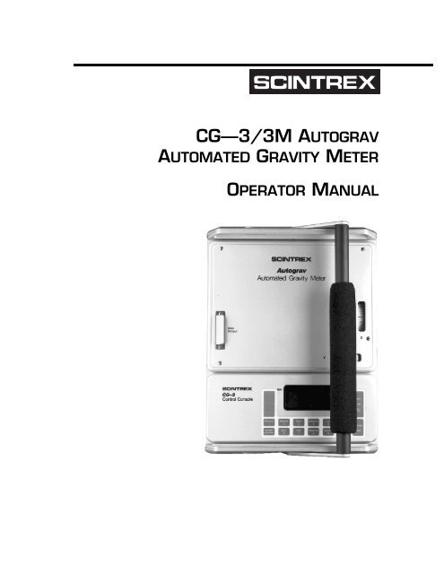
CG–3/<strong>3M</strong> <strong>AUTOGRAV</strong>AUTOMATED GRAVITY METEROPERATOR MANUAL
SCINTREX LIMITEDHead Office In the U.S. In Australia222 Snidercroft RoadConcord, OntarioCanada, L4K 1B5Tel.: (905) 669-2280Fax: (905) 669-6403Telex: 06-964570525 Fort Worth DriveSuite 214Denton, Texas 76201Tel.: (817) 591-7755Fax: (817) 591-19681031 Wellington St.West Perth,West Australia 6005Tel: (619) 321-6934Fax: (619) 481-1201P.N: 858 700Version 5.00August 1995
Autograv CG–3Table of ContentsSection 1: INSTRUMENT OVERVIEWSection 2: GETTING STARTEDUnpacking the Instrument . . . . . . . . . . . . . . . . . . . .2–1Unpacking . . . . . . . . . . . . . . . . . . . . . . . . . . . . . . . .2–2Removing the Dust Cover . . . . . . . . . . . . . . . . . . . . .2–2Starting up the Autograv . . . . . . . . . . . . . . . . . . . . .2–3Powering up the Autograv . . . . . . . . . . . . . . . . . . . .2–4Using the Keypad. . . . . . . . . . . . . . . . . . . . . . . . . . . .2–6The Keypad . . . . . . . . . . . . . . . . . . . . . . . . . . . . . . .2–6Top Functions (Operations Mode) . . . . . . . . . . . .2–7Bottom Functions (Enter Mode) . . . . . . . . . . . . .2–9The Display . . . . . . . . . . . . . . . . . . . . . . . . . . . . . . . . .2–10Parameter Setup Display . . . . . . . . . . . . . . . . . . . . .2–10Menu Structure . . . . . . . . . . . . . . . . . . . . . . . . . . .2–10Moving Between Menus. . . . . . . . . . . . . . . . . . .2–10Selecting a Menu . . . . . . . . . . . . . . . . . . . . . . .2–11Modifying Parameters . . . . . . . . . . . . . . . . . . . .2–12Initializing the Instrument Parameters. . . . . . . . . .2–15The Display during Readings . . . . . . . . . . . . . . . . . .2–25Setting up the Tripod . . . . . . . . . . . . . . . . . . . . . . . .2–26Tripod Extender Legs . . . . . . . . . . . . . . . . . . . . . . . .2–29Temperature Compensation . . . . . . . . . . . . . . . . . .2–31Checking . . . . . . . . . . . . . . . . . . . . . . . . . . . . . . . . .2–31Adjusting Temp. Compensation Offset . . . . . . . . . . . .2–32Adjusting Drift Corrections . . . . . . . . . . . . . . . . . . .2–36Setting up for Field Measurements . . . . . . . . . . . .2–41Recalling Data . . . . . . . . . . . . . . . . . . . . . . . . . . . . . .2–42Scrolling in Memory . . . . . . . . . . . . . . . . . . . . . . . . .2–42Scanning the Records . . . . . . . . . . . . . . . . . . . . . . .2–43Directly Accessing a Record from Memory . . . . . . . . .2–45Recalling Data in the Cycling Mode . . . . . . . . . . . . . .2–46Exiting from the Memory Mode . . . . . . . . . . . . . . . . .2–46Autograv CG–3/<strong>3M</strong> Manual iTable of Contents
Section 3: INSTRUMENT PARAMETERSMain Menu (Auxiliary Mode) . . . . . . . . . . . . . . . . . . 3–1Auxiliary Mode . . . . . . . . . . . . . . . . . . . . . . . . . . . . . . 3–2INITIALISE Menu . . . . . . . . . . . . . . . . . . . . . . . . . . . . 3–3INITIALISE Submenus. . . . . . . . . . . . . . . . . . . . . . . . 3–3LINE SEP . . . . . . . . . . . . . . . . . . . . . . . . . . . . . . . . . . 3–14STN SEP. . . . . . . . . . . . . . . . . . . . . . . . . . . . . . . . . . . 3–15<strong>AUTOGRAV</strong> SETUP . . . . . . . . . . . . . . . . . . . . . . . . . . 3–16<strong>AUTOGRAV</strong> SETUP Submenus. . . . . . . . . . . . . . . . . . 3–16OUTPUT . . . . . . . . . . . . . . . . . . . . . . . . . . . . . . . . . . . 3–30OUTPUT Submenus . . . . . . . . . . . . . . . . . . . . . . . . . 3–31EDIT. . . . . . . . . . . . . . . . . . . . . . . . . . . . . . . . . . . . . . . 3–39LOCK AUX.. . . . . . . . . . . . . . . . . . . . . . . . . . . . . . . . . 3–40Locking the Auxiliary mode . . . . . . . . . . . . . . . . . . . . 3–40Unlocking Auxiliary mode . . . . . . . . . . . . . . . . . . . . . 3–40Section 4: FIELD OPERATIONParameter Setup and Keypad Operation. . . . . . . . 4–1Reading Time — Terminating a Reading . . . . . . . . . . . 4–2Cal. After . . . . . . . . . . . . . . . . . . . . . . . . . . . . . . . . 4–2Levelling Requirements andContinuous Tilt Correction . . . . . . . . . . . . . . . . . . . . 4–3Recording Data . . . . . . . . . . . . . . . . . . . . . . . . . . . . . 4–4Auto Rejection . . . . . . . . . . . . . . . . . . . . . . . . . . . . 4–4Notebook Feature . . . . . . . . . . . . . . . . . . . . . . . . . . 4–5Transporting and Handling . . . . . . . . . . . . . . . . . . . 4–6Operation Hints . . . . . . . . . . . . . . . . . . . . . . . . . . . . . 4–6Transportation . . . . . . . . . . . . . . . . . . . . . . . . . . . . 4–7Motion Noise . . . . . . . . . . . . . . . . . . . . . . . . . . . . . 4–8Wind . . . . . . . . . . . . . . . . . . . . . . . . . . . . . . . . . . . 4–9Base Station Selection . . . . . . . . . . . . . . . . . . . . . . 4–9Cold Weather Operation. . . . . . . . . . . . . . . . . . . . . . 4–10Using the CG-3 before Warm-upStabilization is Complete . . . . . . . . . . . . . . . . . . . . . 4–10Dumping Data . . . . . . . . . . . . . . . . . . . . . . . . . . . . . . 4–11ii Autograv CG–3/<strong>3M</strong> Manual
Section 5: BATTERY AND CHARGERLoss of Power . . . . . . . . . . . . . . . . . . . . . . . . . . . . . .5–1Battery . . . . . . . . . . . . . . . . . . . . . . . . . . . . . . . . . . . .5–2Temperature Effects . . . . . . . . . . . . . . . . . . . . . . . .5–2Voltage . . . . . . . . . . . . . . . . . . . . . . . . . . . . . . . . . .5–3Life Expectancy . . . . . . . . . . . . . . . . . . . . . . . . . . . .5–4Replacing . . . . . . . . . . . . . . . . . . . . . . . . . . . . . . . .5–5Charger . . . . . . . . . . . . . . . . . . . . . . . . . . . . . . . . . . .5–5Charging Time . . . . . . . . . . . . . . . . . . . . . . . . . . . . .5–6Charger Line Voltage . . . . . . . . . . . . . . . . . . . . . . . .5–6Selecting an alternate voltage . . . . . . . . . . . . . .5–6Battery Compartment Fuse . . . . . . . . . . . . . . . . . . .5–8How to Change a Battery. . . . . . . . . . . . . . . . . . . . .5–8Section 6: MAINTENANCETemperature Compensation . . . . . . . . . . . . . . . . . .6–1Drift Correction . . . . . . . . . . . . . . . . . . . . . . . . . . . . .6–2Obtaining Accurate Drift Correction Results . . . . . . .6–2Using a Chart Recorder. . . . . . . . . . . . . . . . . . .6–3Tilt Correction Adjustment. . . . . . . . . . . . . . . . . . . .6–4Tilt Sensor Zero Adjustments . . . . . . . . . . . . . . . . . .6–4Measuring X E . . . . . . . . . . . . . . . . . . . . . . . . . .6–4Fine Adjustment of X E . . . . . . . . . . . . . . . . . . . .6–6Measuring Y E . . . . . . . . . . . . . . . . . . . . . . . . . .6–8Fine Adjustment of Y E . . . . . . . . . . . . . . . . . . . .6–9Tilt Sensor Coarse Zero Adjustment . . . . . . . . . . . . .6–10Coarse Adjustment of X E . . . . . . . . . . . . . . . . . .6–10Coarse Adjustment of Y E . . . . . . . . . . . . . . . . . .6–11Tilt Sensor Sensitivity Adjustment (TILTXS, TILTYS) . . . .6–12Measuring X-axis Sensitivity . . . . . . . . . . . . . . .6–12Adjusting X-axis Sensitivity . . . . . . . . . . . . . . . .6–1<strong>3M</strong>easuring Y-axis Sensitivity . . . . . . . . . . . . . . .6–14Adjusting Y-axis Sensitivity . . . . . . . . . . . . . . . .6–15Tilt Sensor Cross-Coupling . . . . . . . . . . . . . . . . . . . .6–16Measuring . . . . . . . . . . . . . . . . . . . . . . . . . . . .6–16Adjusting . . . . . . . . . . . . . . . . . . . . . . . . . . . . .6–17Recalibrating the Gravimeter. . . . . . . . . . . . . . . . . .6–18Tripod Maintenance . . . . . . . . . . . . . . . . . . . . . . . . .6–20Storing the Autograv . . . . . . . . . . . . . . . . . . . . . . . .6–20Table of ContentsAutograv CG–3/<strong>3M</strong> Manual iii
Section 7: TROUBLESHOOTINGSection 8: REFERENCE INFORMATIONAutograv Specifications . . . . . . . . . . . . . . . . . . . . . . 8–1Standard Accessories . . . . . . . . . . . . . . . . . . . . . . . 8–2Optional Accessories . . . . . . . . . . . . . . . . . . . . . . . . 8–3Application Software . . . . . . . . . . . . . . . . . . . . . . . . 8–4Training. . . . . . . . . . . . . . . . . . . . . . . . . . . . . . . . . . . . 8–4Instrument Parts List. . . . . . . . . . . . . . . . . . . . . . . . 8–5CG-3 Gravity Meter . . . . . . . . . . . . . . . . . . . . . . . . . 8–5Options and Accessories . . . . . . . . . . . . . . . . . . . . . 8–5Spare Parts Kit . . . . . . . . . . . . . . . . . . . . . . . . . . . . . 8–6Warranty and Repair . . . . . . . . . . . . . . . . . . . . . . . . 8–7Warranty . . . . . . . . . . . . . . . . . . . . . . . . . . . . . . . . 8–7Repair . . . . . . . . . . . . . . . . . . . . . . . . . . . . . . . . . . 8–7When to Ship the Unit . . . . . . . . . . . . . . . . . . . 8–7Description of Problem . . . . . . . . . . . . . . . . . . . 8–8How to Ship the Unit . . . . . . . . . . . . . . . . . . . . 8–8Appendix A: THEORY OF OPERATIONIntroduction . . . . . . . . . . . . . . . . . . . . . . . . . . . . . . . . A–1Control Console and Software . . . . . . . . . . . . . . . . . A–5Spring Service Life and Reading Range . . . . . . . . . A–7Processing of the Gravity Signal. . . . . . . . . . . . . . . A–10Compensation and Corrections. . . . . . . . . . . . . . . . A–12Drift Correction . . . . . . . . . . . . . . . . . . . . . . . . . . . A–12Tilt Correction (TIC) . . . . . . . . . . . . . . . . . . . . . . . . . A–13Temperature Compensation (TEC) . . . . . . . . . . . . . . . A–15Earth Tide Correction (ETC) . . . . . . . . . . . . . . . . . . . A–16Residuals. . . . . . . . . . . . . . . . . . . . . . . . . . . . . A–16Gravity Offset (GREF) . . . . . . . . . . . . . . . . . . . . . . . A–17Appendix B: ELASTIC HYSTERESIS EFFECTSiv Autograv CG–3/<strong>3M</strong> Manual
Appendix C: INTERFACING WITH THE <strong>AUTOGRAV</strong>RS 232C Standard . . . . . . . . . . . . . . . . . . . . . . . . . .C–1IGS Output . . . . . . . . . . . . . . . . . . . . . . . . . . . . . . . . .C–2Serial I/O Connections . . . . . . . . . . . . . . . . . . . . . . .C–2Serial Data Format . . . . . . . . . . . . . . . . . . . . . . . . .C–5Text Transmission Sequence . . . . . . . . . . . . . . . . . . .C–6Communication Software . . . . . . . . . . . . . . . . . . . . .C–6Appendix D:INITIAL CONSTANTS SHEETINDEXTable of ContentsAutograv CG–3/<strong>3M</strong> Manual v
vi Autograv CG–3/<strong>3M</strong> Manual
Autograv CG–3Section1INSTRUMENT OVERVIEWThe Autograv is a microprocessor-based automated gravity meter that has ameasurement range of over 7000 mgals without resetting and a reading resolutionof 0.005 mGals (CG–3) or 0.001 mGal (CG–<strong>3M</strong>). This enables theAutograv to be used for both detailed field investigations and large scale regionalor geodetic surveys.IntroductionAccurate measurements are taken by simply pressing a key, and under mostconditions it takes under one minute to complete the reading. A series ofreadings of gravity measurements at a fixed site can be performed by settingthe Autograv in the cycling mode. The Autograv obtains a reading by continuouslyaveraging a series of one second samples. The reading is displayedon the LCD directly in mGals. The data is stored in the solid state memoryand can be sent to a printer, modem, recorder or microcomputer.The gravity sensor, solid-state control system and battery are integrated intoa single instrument housing, which doubles as a carrying case. This eliminatesthe need for packing and unpacking the sensor between readings. Stabilityis increased and the risk of an accident is reduced by the absence ofan external cable between the battery and sensor. The kinetic mounting systemwhich indexes the Autograv onto the tripod further increases instrumentstability.When setting the Autograv up for a reading, the electronic tilt sensors providegreater accuracy and are easier to operate than the conventional bubblelevels. The gravity meter displays the outputs from the sensors on highresolution meters on the front panel and also on the 80 character liquidcrystal display.Autograv CG–3 Manual 1-1
Instrument OverviewExcellent protection from changes in ambient temperature and atmosphericpressure is achieved by sealing the Autograv sensing element in a temperaturestabilized vacuum chamber. The wide operating temperature of -40°Cto +45°C (optional +35°C or +55°C) enables the operator to use the Autogravin many environments. Since the sensor is made from non-magnetic fusedquartz, the Autograv is not affected by magnetic field variations (as long asthey are less than ten times the Earth’s magnetic field, i.e. ± 0.5mT).Low drift is a result of the extremely stable operating environment of thequartz elastic system. It allows the long term drift of the sensor to be accuratelypredicted and a real time software correction reduces it to less than0.02 mGals per day.Internal tilt sensors constantly supply the Autograv with information whenan operator selects the continuous tilt correction feature. If measurementsare taken on unstable ground, errors due to the movement of the Autogravare automatically eliminated.An automatic tidal correction can also be selected via the keyboard. The operatorenters in the geographical location and time zone information andthe Autograv automatically calculates and applies a real time tidal correctionto each reading.The internal 12 volt rechargeable battery provides sufficient power to operatethe Autograv throughout a normal survey day. An operator can check thebattery voltage at any time by pressing a key and viewing the display. Whenthe battery voltage is approaching the discharge level, the Autograv emits anaudible alarm. An optional cable enables the instrument to operate fromany external 12 volt DC power supply or battery which can supply 3 amperespeak current. In the event of a main battery failure, a set of built-in miniaturebatteries keeps the memory safe for several days.1-2 Autograv CG–3 Manual
Autograv CG–3 Manual 1-3Introduction
Instrument OverviewFigure 1Autograv — The Automated Gravity Meter1-4 Autograv CG–3 Manual
Autograv CG–3Section2GETTING STARTEDUNPACKING THE INSTRUMENTThe Autograv is packed in an insulated case (with the battery disconnectedto comply with transport safety regulations) in order to protect theinstrument during shipment.How ToATTENTION:During shipmentthe battery must bedisconnected.If you have justreceived yourCG–3, the batteryis fully charged, butdisconnected.Please reconnectthe battery (seestep 6 on page 2-5)before operatingAutograv CG–3 Manual 2-1
Getting StartedFigure 2Autograv Transportation CaseUNPACKING1. Pull up the tab of the link lock and turn the tab counter-clockwise tounfasten the lock from the keeper plate.2. Repeat step 1 for the other link lock.3. Open the Autograv transportation case by lifting the cover.4. Remove the protective foam from the left hand side of thetransportation case to view the top of the Autograv dust cover plate.5. Remove the Autograv from the transportation case and visually inspectfor any physical damage that may have occurred during transportation.Important: If there is any evidence of physical damage, immediatelycall <strong>Scintrex</strong> Limited.6. From the right hand side of the transportation case, remove theAutograv accessories.REMOVING THE DUST COVER1. Remove the dust cover plate on the Autograv by pressing down on thetwo latches and sliding the cover away from the instrument.2. Place the dust cover back inside of the transportation case for safekeeping.Note:If you are shipping the Autograv, insert the dust cover to protectthe instrument.2-2 Autograv CG–3 Manual
Starting up the AutogravSTARTING UP THE <strong>AUTOGRAV</strong>Starting-up the Autograv for the first time, or after it has been turned off formore than 48 hours, requires the following steps and waiting periods.1. Powering up the Autograv —The charger powers up theinstrument and also charges the battery.2. Warm-up period —After you connect the battery charger to theAutograv, it requires a 4 hour warm-up time in order to reach theoperating temperature.3. Stabilization period —The instrument requires a 48 hour periodafter you connect the battery charger to stabilize. This is a good time tobecome familiar with the keypad and software. You can initialize thesoftware by resetting the time and date, erasing the memory and settingup the Autograv parameters.You can unplug the battery charger from the Autograv to take testreadings during the stabilization period however, you must reconnectthe charger after the readings are complete or if the Autograv emits thelow battery alarm.How To4. Checking and adjusting the temperature compensation —You check and adjust the temperature compensation after theinstrument is stable. (Refer to page 2-35)5. Checking and adjusting the drift correction—You check andadjust the drift correction after the temperature compensation hasbeen checked (or adjusted if necessary). This procedure involvesrunning the Autograv for approximately 24 hours in the cycling mode(unattended). (Refer to page 2-41)6. Setting up the instrument for field operations—You can setup your Autograv for field use after you complete the previous steps.(Refer to Section 4 - Field Operation)Autograv CG–3 Manual 2-3
Getting StartedPOWERING UP THE <strong>AUTOGRAV</strong>1. Set the charger to the appropriate line voltage (115V or 230V) by adjustingthe voltage setting switch on the charger.2. Check the charger fuse by unscrewing the fuse holder. Each voltagesetting requires a different fuse rating.Fuses are available in the Spare Parts Kit.Voltage Fuse115V 0.75A230V 0.375A3. After you have set the charger voltage and checked the fuse, plug thepower cord of the charger into an AC outlet. The green light on thecharger turns on to indicate that the charger is working.Figure 3Front View of the Autograv with Charger2-4 Autograv CG–3 Manual
Powering up the Autograv4. Remove the dust cap from the charger plug on the Autograv.5. While holding the top of the instrument, insert the charger connectorto the charger plug on the Autograv.6. Open the battery compartment by pressing down on the two latchesand lifting the cover away from the instrument.7. Remove the battery by pushing on the left side of the battery and thenpulling the black tab towards you so the battery can slide out of thecompartment.8. Insert the connector of the battery into either socket on the left side ofthe compartment. The Autograv has two sockets so that you can changebatteries without powering down the instrument (see Figure 4).9. Before you reinstall the battery, place your hand inside and flatten theblack tab against the bottom, side and top of the compartment. If theblack tab is not pressed against the walls of the compartment, thebattery will not fit and the foam padding will be damaged.How To10.Place the battery inside of the compartment with the top of the batteryfacing outwards and the battery cable to the left as shown in Figure 4.11.Reinstall the battery compartment cover.Autograv CG–3 Manual 2-5
Getting StartedFigure 4Position Of Battery Inside Compartment2-6 Autograv CG–3 Manual
Using the KeypadUSING THE KEYPADFigure 5The Autograv KeypadHow ToTHE KEYPADYou can use the Autograv keypad to:▲▲▲▲▲▲▲Select menu optionsSet system parametersTake a readingRecord dataRecall stored dataDump dataReset the instrumentEach key has two functions. The mode of operation determines which functionthe Autograv responds to. The two modes of operation are:Operation mode—In this mode, the key press initiates the function that isdisplayed at the top of each key.Enter mode—In this mode, the key press initiates the function that is displayedat the bottom of each key.Autograv CG–3 Manual 2-7
Getting StartedNote:If the keypad is not responding to a key press, then you needto reset the Autograv by pressing and holding the ON/OFF(w) key for more than 5 seconds.Top Functions (Operations Mode)KeywON/OFFDescription— Turns the instrument on and off.When you turn on the instrument, the previous menuoption appears on the display (i.e. the status of the instrumentis saved when the Autograv is turned off).r1METHOD2DATA384LINENote:If the instrument is busy printing, measuring orhung-up, then you must press the ON/OFF keyfor more than 5 seconds, to reset the instrumentRECORD — Enters measurements into memory.— Displays the method/mode in which the instrumentis currently operating.The selectable modes are FIELD, CYCLING or NONE.— Shows on the display the set of measurementparameters being measured or just completed.MEMORY — Recalls and displays data that is stored inmemory by scrolling.— Shows the present line number and/or a linenumber recalled from memory (if applicable). The currentline appears on the top line while the line numberfrom memory is on the second line.It also enables you to change the current line number.2-8 Autograv CG–3 Manual
Using the KeypadKey506AUXDescriptionSCROLL KEYS — Perform two functions:1. Scroll through lists of selected data, actions or themenu options2. Goes to the next line or station if line or stationnumber is displayed— Displays the AUXILIARY mode menu options.Use the AUX key to exit from a submenu and to return tothe previous menu level.7INFO9STATIONIf you press the AUX key twice, then the software takesyou from your immediate menu to the first level menu(i.e. the Main menu).Pressing the AUX key, while the meter is measuring, willcancel the measurement.— Provides remaining memory capacity, batteryvoltage, time and date, grid number and notebook information.— Displays the current station number and/ora station number for a measurement in memory.The current station appears on the top line while thestation number in memory is on the second line.How ToeCHANGEIt enables you to change the current station number.— Enables you to select the ENTER mode soyou can modify parameters using the bottom functionsof each key.Autograv CG–3 Manual 2-9
Getting StartedKeyDescriptionSTART/STOP — Enables you to:q• Start or stop a measurement• Start or stop the output of data tocommunication or recording devices• Start erasing and testing memory• Start the EDIT modeBottom Functions (Enter Mode)KeywCLEARDescription— Erases the current number.09r•0–9 — Inputs numerical data— Enters a decimal pointqeENTER+/– or NE/ SW -— Toggles between north, south,east, west and +/– for station and line numbers.— Enables you to:• access the menu option shown on the display• to enter a selected value into memory.2-10 Autograv CG–3 Manual
The DisplayTHE DISPLAYPARAMETER SETUP DISPLAYThe Autograv display is an 80 character liquid crystal display (LCD) arrangedin 4 rows of 20 digits in each row. For example:DATA IDENTIFIERCURRENT DATAPROMPTSTATION 100E 1CHANGE? 0LINE 100N 0STATION 0E %PRECEDING DATAAVAILABLEMEMORYHow ToHowever, not all areas of the display will have information:▲▲If you are in the first level of menu, then there is no current orprevious data so these areas will be blank.If you select a menu option that does not have previous data, thenthis area will be blank.MENU STRUCTUREThe Autograv has three levels of menus. Refer to the Instrument Parameterssection (page 3-1) for a detailed description of the Autograv software.Moving Between MenusWhen you press a function key in the OPERATION mode, you will see a menuoption appear on the display.Autograv CG–3 Manual 2-11
Getting StartedExample: Press: 6 AUX<strong>AUTOGRAV</strong> SETUPENTER?1. By pressing ENTER, one item of the menu list appears on the display.2. If you want to go to the next menu option in the same level, then:Press: 5 or 0 (SCROLL)keys3. If you want to go to the submenu of the displayed menu, then press thekey shown on the second line of the display prompt.4. To go back to the previous level of menu, press the 6 (AUX) key.Selecting a MenuWhen the display shows the menu option that you want to select, press thekey that is shown on the second line.Example:<strong>AUTOGRAV</strong> SETUPENTER?KEY TO PRESSPress: e(ENTER) key.MODE: FLD GRAVCHANGE?KEY TO PRESSPress: e(CHANGE) key2-12 Autograv CG–3 Manual
The DisplayModifying ParametersThe prompt that is on the second line shows you how to change the parameterthat is displayed. There are three types of prompts:PROMPT KEYS TYPESELECT/ENTER 5 or 0limited to selectionxxxx> nnnENTER?0 to 9,r,w (CLEAR) ,qnumerical values,N,S,E,W, +/–xxxxCHG? >xxxx< e (CHANGE) limited to 2 selectionsHow To▲▲If you change the parameter by using the 5 or 0 (SCROLL) keys,or change a numerical value, then you must press the ENTER key toload the change into memory.If you are enabling or disabling a parameter, then you do not have topress the ENTER key.Example:To change the read time from 65 secs to 120 secs:READ TIME 65CHANGE?Press: e(CHANGE)READ TIME>65ENTERAutograv CG–3 Manual 2-13
Getting StartedType: 120(120)READ TIME> 120ENTERPress: e(ENTER)READ TIME 120CHANGE?2-14 Autograv CG–3 Manual
The DisplayHow ToAutograv CG–3 Manual 2-15
Getting Started2-16 Autograv CG–3 Manual
The DisplayFigure 6Autograv Software Flowchart For Auxiliary ModeHow ToAutograv CG–3 Manual 2-17
Getting StartedINITIALIZING THE INSTRUMENTPARAMETERSTo prepare the instrument to take a reading, you must first initialize someparameters by doing the following:▲▲▲Reset time and dateErase memorySetup the Autograv parametersNote:If a key is not pressed within approximately one minute, thedisplay automatically turns off. However, the Autograv bringsyou back to the same place in the menu where you left offwhen you press the w(ON) key.1. To Reset Time and DateKey to Press66(AUX) twiceDisplayCurrent Menu5 or 0 until... INITIALISEENTER?eCurrent Menu5 or 0 until... TIME xx:xx:xxCHANGE? xx/xx/xxe(CHANGE) TIME HH:xx:xxENTER2-18 Autograv CG–3 Manual
Initializing the Instrument ParametersKey to PressDisplayHH(Value for hour)TIMEENTERHH:xx:xx(ENTER)eTIME xx:MM:xxENTERMM(Value for minutes)TIMEENTERxx:MM:xxe (ENTER) TIME xx:xx:SSENTERSS(Value for seconds)TIME:ENTERxx:xx:SSHow Toe (ENTER) DATE: xx/xx/xxENTERRepeat the steps shown above to set the current date.After you type the day and press the ENTER key, the clock starts to run.Autograv CG–3 Manual 2-19
Getting Started2. To Erase MemoryKey to Press66(AUX) twiceDisplayCurrent Menu5 or 0 until... INITIALISEENTER?e (ENTER)Current Menu5 or 0 until... ERASE MEMORYENTER?e (ENTER)ERASE MEMORYSTART?q (START/STOP) MEMORYFREE 100%TESTED XXKXXK is the size of the memory installed in the Autograv. For example: 48K2-20 Autograv CG–3 Manual
Initializing the Instrument Parameters3. Autograv SetupCycling andRead TimeSetupKey to Press66(AUX twice)Current MenuDisplay5 or 0 until... <strong>AUTOGRAV</strong> SETUPENTER?e (ENTER)Current Menu5 or 0 until... MODE:XXXXCHANGE?e (CHANGE)MODE:XXXXSELECT/ENTERHow To5 or 0 until... MODE:>CYCLINGSELECT/ENTERe (ENTER)0(SCROLL down)MODE:CYCLINGCHANGE?READ TIME XXXCHANGE?e (CHANGE)120(120)READ TIME>XXXENTERREAD TIME>120ENTERAutograv CG–3 Manual 2-21
Getting StartedKey to PressDisplaye (ENTER) READ TIME 120CHANGE?0(SCROLL down)CYCLE TIME XXXCHANGE?Chart SelectSetupe (CHANGE)600(600)CYCLE TIME>XXXENTERCYCLE TIME>600ENTERe (ENTER) CYCLE TIME 600CHANGE?0(SCROLL down)CHART SELECT:XXCHANGE?e (CHANGE)CHART SELECT:>XXSELECT/ENTERSTOP ERRSetup555 until...CHART SELECT:>1ENTERe (ENTER) CHART SELECT: 1CHANGE?0(SCROLL down)STOP:ERR.XXXX
Initializing the Instrument ParametersKey to Pressee(CHANGE until...)0(SCROLL down)DisplaySTOP:ERR.DISABLED12ENTERCAL. AFTER>12ENTER(ENTER) CAL. AFTER 12CHANGE?0(SCROLL down)ee(CHANGE until...)0(SCROLL down)ee(CHANGE until...)0(SCROLL down)CONT.TILT CORR.CHG?>XXXXDISABLEDXXXXSELECTEDXXXX
Getting StartedLAT and LONGSetupKey to Pressee(CHANGE until...)0(SCROLL down)TIDE CORRECTIONCHG?>SELECTEDDDENTERe (ENTER)0(SCROLL down)DEG. LAT DDCHANGE?DEG. LONG XXCHANGE?e (CHANGE)DEG. LONG XXENTERDecimal degrees ofthe reading siteW is + (positive)E is – (negative)DEG. LONG>DDENTERe (ENTER)DEG. LONG DDCHANGE?2-24 Autograv CG–3 Manual
Initializing the Instrument ParametersGMT SetupKey to PressDisplay0(SCROLL down)GMT. DIFF XXCHANGE?e (CHANGE)GMT. DIFF>XXENTER(GMT—Clock time)in hoursGMT. DIFF>HHENTERAUTORECORDSetup(e.g. Toronto =+5hrsor +4 during daylightsavings time)e (ENTER)GMT. DIFF HHCHANGE?How To0(SCROLL down)AUTO RECORDCHG?>XXXDISABLEDXXENTER0 (0) GREF.>0ENTERe (ENTER) GREF. 0CHANGE?Autograv CG–3 Manual 2-25
Getting StartedDRIFT CORRSetupKey to Press0(SCROLL down)DisplayDRIFT CORRECT.ENTER?e (ENTER)Current Menu5 or 0 until... DRIFT XXCHANGE?e (CHANGE)DRIFT>XXENTERNumerical value(From constantsheet or most recentvalue)DRIFT>VVENTERe (ENTER)0(SCROLL down)ee(CHANGE) twiceDRIFT VVCHANGE?CHG. START TIMEENTER?CHG. START TIMEENTER?The drift correction start time is now set to the current time and date onthe clock.6 (AUX) DRIFT CORRECT.ENTER?2-26 Autograv CG–3 Manual
Initializing the Instrument ParametersInitialConstantsSetupKey to Press0(SCROLL down)e(ENTER) andthen 5 or 0(SCROLL) until...INIT. CONST.ENTER?GCAL.1 XXCHANGE?Displaye (CHANGE)GCAL.>XXENTEREnter the numerical value from the INSTRUMENT CONSTANTS sheet.(Every instrument has its own set of initial constants. These must matchthe parameters setup in the INITIAL CONSTANTS mode.)How Toe (ENTER)0(SCROLL down)GCAL. 1 XXCHANGE?GCAL. 2 XXCHANGE?Follow the key press steps (as shown in the previous four steps) for all fiveof the initial constants and set the values to match the instrument’s individualconstants. sheet values.6 (AUX) INIT. CONST.ENTER?0(SCROLL down)MODE: CYCLINGCHANGE?You are now back to the top/start of the <strong>AUTOGRAV</strong> SETUP submenu.Autograv CG–3 Manual 2-27
Getting StartedTHE DISPLAY DURING READINGSAfter you press the START key to initiate a reading, the display goes throughtwo display changes to enable you to level the Autograv before you actuallystart a reading.The first display indicates that the Autograv is in the ADJUST mode. Within afew seconds, the display changes to show you the values of the X and Y tilts,as follows:LEVELING PARAMETERSVALUESTILTS X:XXX 1ADJUST Y: XXX 0LINE 100 0STATION 0 %AVAILABLEMEMORYREADVERTICALLYTo level the instrument, read the display and analog tilt meters, and then adjustthe tripod until the Autograv is level.2-28 Autograv CG–3 Manual
The Display during ReadingsPress the START key to start the reading. The display then goes into thePAUSE mode to enable the instrument to settle after the button is pushed.Within a few seconds, the gravity reading appears on the second display asfollows:DURATION OF READINGGRAVITY READINGGRAV. XX.XXX 1DURXER. X.XXX0LINE 100 0STATION 0 %AVAILABLEMEMORYREADVERTICALLYERROR OR STANDARD DEVIATION (SD)How ToAutograv CG–3 Manual 2-29
Getting StartedSETTING UP THE TRIPODThe tripod enables you to level the Autograv before taking a reading. Thethree leveling screws on the bottom of the tripod are adjusted until the X andY meters on the front panel of the Autograv and the display show that theAutograv is level.Figure 7Setup of the Tripod2-30 Autograv CG–3 Manual
Setting up the TripodTo set up1. Set the tripod on stable ground in a quiet location with the bubble levelaway from you as shown in the previous diagram (Figure 7).2. Place the cone on the bottom of the instrument (left side) down ontothe left rear tripod foot.3. Place the slot on the bottom of the instrument (right side) down ontothe right rear tripod foot.4. Lower the instrument onto the front tripod foot.q5. Press the START key.The following prompts appear one after the other:<strong>AUTOGRAV</strong>ADJUSTHow ToTILTS X: XXXADJUST Y: XXX6. View the X and Y meters on the front panel and the display to level theinstrument.Autograv CG–3 Manual 2-31
Getting StartedFigure 8Adjusting the TripodTo LevelYou have two options for leveling the Y-axis of the CG-3/<strong>3M</strong>. The fastest wayto level the meter is to adjust both rear screws on the tripod as outlined inStep 7. The other option for high precision microgravity measurements is toset one of the rear screws in the middle of its range and tape over it. Adjustthe other rear screw until the Y-axis is level. This method ensures that the elevationof the CG-3/<strong>3M</strong> sensor relative to the tripod is strictly maintained.2-32 Autograv CG–3 Manual
Setting up the Tripod7. Adjust the Y-axis first by turning the two rear screws on the tripod andviewing the display and bubble meters.If you need to level the Y-axis in the positive direction, then turn therear screws towards the front of the instrument. (See Figure 8 above.)This procedure of rotating both screws in opposite directions at thesame time is the most efficient way to level about the Y-axis.8. After the Y-axis is level, adjust the X-axis by turning the front screw onthe tripod and viewing the display and bubble meters.If you need to level the X-axis in the positive direction, then turn thefront screw clockwise. (See Figure 8 on page 2-32.)TRIPOD EXTENDER LEGSThe tripod comes with three extender legs which may be used under softsoil conditions.How ToTo set up1. Place one extender leg over one of the pointed bottom legs of the tripodwith the tab of the extender leg facing the outside of the tripod.This tab is available so that you can step on the tab to dig the shaft ofthe leg into the soil.2. Insert the 8-32 hex bolt through the openings of the legs. Ensure that thehead of the nut fits into the recessed slot on the extender leg as thisenables you to securely tighten the bolt.3. Place the washer and the black wing nut onto the bolt and slightlytighten the wing nut.4. Adjust the angle of the extender leg and tighten the wing nut.5. Repeat steps 1 through 4 for the other two extender legs.Autograv CG–3 Manual 2-33
Getting StartedFigure 9Tripod with Extender Legs2-34 Autograv CG–3 Manual
Temperature CompensationTEMPERATURE COMPENSATIONImportant: Do not adjust the temperature compensation until theAutograv has gone through the complete stabilizationtime of 48 hours. If you can not wait for 48 hours, thenplease refer to “Using the CG-3 before Warm-up Stabilizationis Complete” on page 4-10.CHECKING1. Select a stable base for the Autograv in a quiet location and place theinstrument on the tripod (with extender legs removed).2. Level the Autograv by following the steps outlined in “Setting up theTripod” on page 2-30.3. When the following prompt appears,How ToTILTS X: XXXADJUST Y: XXXpress the 0 (SCROLL DOWN) key. The following prompt appears:TEMP. X.XXADJUSTa. If the number on the top line of the display is between +1.0and -1.0, then the temperature of the gravity sensor iswithin range. Please proceed to the section “Adjusting DriftCorrections” on page 2-41.b. If the temperature value is outside of the acceptable range,you must adjust the temperature compensation offset.Autograv CG–3 Manual 2-35
Getting StartedADJUSTING TEMP. COMPENSATION OFFSET1. Using a slot-head screwdriver, unscrew the four 4-40 oval screws fromthe faceplate of the Autograv.2. Remove the faceplate.SCREWS TO BEREMOVEDFigure 10 Faceplate of Autograv2-36 Autograv CG–3 Manual
Temperature CompensationHow ToAutograv CG–3 Manual 2-37
Getting StartedFigure 11 Autograv Faceplate Removed2-38 Autograv CG–3 Manual
Temperature CompensationTo AdjustAdjust the Temperature Compensation Fine Adjustment Potentiometer (R1)until the display is close to 0.0 (i.e. within the range of -0.1 to +0.1.)Counter-clockwise = positiveIf the temperature value adjusts to this range, then replace the cover.If the temperature value cannot be adjusted to be withinthe specified range, then:1. Centre R1 by turning the potentiometer clockwise 25 turnsfollowed by 10 turns counter-clockwise.2. Using a slot head screwdriver, remove the four M2.5 x 5mm flathead screws from the Temperature Coarse Adjustment cover.3. Underneath the cover is an O-ring seal. This ensures that nomoisture or dust can enter into the adjustment pot. Remove theO-ring seal and place it in a dry, clean place.(See Figure 11 on page 2-38.)How To4. View the position of the Coarse Adjustment screw. You only needto slightly move the screw to make an adjustment.BEFORE TURNING THE SCREW, CAREFULLY NOTE ITS POSITION.Clockwise = positiveCounter-clockwise = negativeAfter making a very small adjustment of a few degrees, waitseveral seconds for the system to stabilize before reading thetemperature value.Note:Do not push down on the coarse adjust screw, as this coulddamage the adjustment potentiometer.5. Adjust the Coarse Adjustment Screw to bring the temperaturereading to as close to zero (0.0) as possible.6. Adjust the Fine Adjustment potentiometer until the reading iswithin the range of -0.1 to +0.1.7. Wait a few minutes and then check the reading.Autograv CG–3 Manual 2-39
Getting Started8. Readjust the Fine Adjustment potentiometer, if necessary.Note:If the reading does not come within the range with a coarse adjustmentof 1 turn in either direction, contact <strong>Scintrex</strong> Limited.9. Replace the cover(s).2-40 Autograv CG–3 Manual
Adjusting Drift CorrectionsADJUSTING DRIFT CORRECTIONSImportant: You must first check and adjust the temperature compensationbefore you can adjust the drift correction.1. Measure Drift1. After you adjust the temperature compensation, press the 0(SCROLL DOWN) key to display the X and Y Tilts.2. Level the instrument (using the tripod setup procedures) to within -10to +10 arcseconds about both axis.Level the Y-axis, rear footscrews, first.3. Press the START key. The instrument starts a reading.How ToIf the reading appears to be out of range (top line of display) refer tounlatching the sensor on page 7-1 of the Troubleshooting section.4. The Autograv now automatically takes and records a reading onceevery 600 seconds.5. After approximately 24 hours, press the STOP or AUX key if theinstrument is taking a measurement. Otherwise, press the STOP key.This stops the reading cycle.If any of the DATA, INFO or SCROLL keys are pressed, then the displaywill appear to be locked-up. You must then press and hold the ON keyfor more than 5 seconds to reset the instrument.If any other key is pressed while the meter is in the OFF stage of theCYCLE mode, then you must press the STOP key to stop cycling.6. Output the data to a printer or computer.Autograv CG–3 Manual 2-41
Getting Started6502. Output Data1. Press the 6 (AUX) key2. Press the 5 or 0 (SCROLL) key until the following promptappears:OUTPUTENTER?eNote:You must setup the baud rate, data bits and carriage return ofthe printer before you dump data. Refer to the InstrumentParameter Section, starting on page 3-37, on how to set theseparameters.3. Press the ENTER key. The following prompt appears:<strong>AUTOGRAV</strong>START DUMPqExample4. Press the START key.The following is a sample printout of output data:-------------------------------------------------------------------------------SCINTREX V4.1 <strong>AUTOGRAV</strong> / Cycling Mode R4.4Cycle Time: 150 Ser No: 8267.Line: 2. Grid: 0. Job: 0. Date: 95/05/08 Operator: 0.DRIFTR1,T1GREF.: -4158. mGals Tilt x sensit.: 296.5GCAL.1: 6131.436 Tilt y sensit.: 283.8GCAL.2: 0. Deg.Latitude: 43.7TEMPCO.: -0.1241 mGal/mK Deg.Longitude: 79.6Drift const.: 0.18 GMT Difference: 4.hrDrift Correction Start Time: 11:57:16 Cal.after x samples: 12Date: 95/04/13 On-Line Tilt Corrected = "*"-------------------------------------------------------------------------------Station Grav. SD. Tilt x Tilt y Temp. E.T.C. Dur # Rej Time0. 41.684 0.041 2. -2. -0.69 -0.023 120 0 14:03:570. 41.685 0.037 1. -3. -0.67 -0.023 120 0 14:06:270. 41.684 0.044 2. -3. -0.65 -0.023 120 1 14:08:572-42 Autograv CG–3 Manual
Adjusting Drift CorrectionsR2,T20. 41.683 0.031 1. -3. -0.65 -0.023 120 0 14:11:270. 41.682 0.036 1. -3. -0.65 -0.024 120 0 14:13:570. 41.682 0.034 1. -3. -0.64 -0.024 120 0 14:16:270. 41.680 0.033 2. -3. -0.64 -0.024 120 0 14:18:570. 41.682 0.045 2. -3. -0.64 -0.024 120 0 14:21:270. 41.681 0.036 2. -3. -0.64 -0.024 120 1 14:23:570. 41.681 0.038 1. -3. -0.64 -0.023 120 0 14:26:270. 41.683 0.038 1. -3. -0.64 -0.023 120 0 14:28:570. 41.679 0.042 1. -4. -0.63 -0.023 120 0 14:31:270. 41.681 0.034 1. -4. -0.64 -0.023 120 0 14:33:570. 41.682 0.043 2. -3. -0.64 -0.023 120 0 14:36:270. 41.680 0.035 2. -3. -0.64 -0.023 120 0 14:38:570. 41.681 0.037 2. -3. -0.64 -0.023 120 0 14:41:270. 41.679 0.037 2. -3. -0.63 -0.023 120 0 14:43:570. 41.682 0.032 2. -3. -0.63 -0.023 120 0 14:46:270. 41.683 0.039 2. -3. -0.63 -0.023 120 0 14:48:570. 41.681 0.039 2. -3. -0.64 -0.023 120 0 14:51:270. 41.679 0.049 2. -3. -0.64 -0.022 120 0 14:53:570. 41.679 0.039 2. -3. -0.64 -0.022 120 0 14:56:270. 41.678 0.038 2. -3. -0.64 -0.022 120 0 14:58:570. 41.682 0.040 2. -3. -0.63 -0.022 120 0 15:01:270. 41.681 0.038 2. -3. -0.64 -0.022 120 0 15:03:570. 41.680 0.042 2. -3. -0.63 -0.022 120 0 15:06:270. 41.679 0.044 2. -3. -0.63 -0.021 120 0 15:08:570. 41.680 0.040 2. -3. -0.63 -0.021 120 0 15:11:270. 41.684 0.038 2. -3. -0.63 -0.021 120 0 15:13:570. 41.678 0.039 2. -3. -0.63 -0.021 120 0 15:16:270. 41.681 0.036 2. -3. -0.63 -0.020 120 0 15:18:570. 41.681 0.043 2. -3. -0.63 -0.020 120 0 15:21:270. 41.681 0.041 2. -3. -0.63 -0.020 120 0 15:23:570. 41.680 0.044 2. -3. -0.63 -0.020 120 0 15:26:270. 41.682 0.040 2. -3. -0.63 -0.019 120 0 15:28:57.....0. 41.749 0.039 1. -3. -0.63 -0.016 120 0 01:51:270. 41.742 0.037 2. -3. -0.63 -0.016 120 0 01:53:570. 41.743 0.044 2. -3. -0.63 -0.016 120 0 01:56:270. 41.741 0.041 1. -3. -0.63 -0.015 120 1 01:58:570. 41.749 0.041 1. -3. -0.63 -0.015 120 0 02:01:270. 41.749 0.040 1. -3. -0.63 -0.014 120 0 02:03:570. 41.745 0.031 1. -3. -0.63 -0.014 120 0 02:06:27How To3. Reading the Data1. From the listing, take one reading (R1) at time T1 close to the start ofthe recording period and another reading (R2) at time T2 from nearthe end of the period.Do not use readings which are obviously noisy or disturbed.2. From these values, calculate a new Drift Correction.DRIFT′ = DRIFT +R2--------------------– R1T2 – T1Autograv CG–3 Manual 2-43
Getting Startedwhere:DRIFT is the Drift constant in the instrument during readings(T2-T1) is in units of days.Example:The data from the printout on page 2-42 was used to calculate the followingdrift value.Selecting: T2 = 02:03:57 on 95/05/09T1 = 14:03:57 on 95/05/08Gives the corresponding readings:R2 = 41.749R1 = 41.684andDRIFT = 0.18 (from the dump’s header: Drift const.)R2 – R1 = 0.065mGalT2 – T1 = 12 hrs = 0.50 daysTherefore,DRIFT′ = 0.18 +0.065--------------0.5DRIFT´ = 0.31 mGal/day6e4. Adjusting the Drift Correction1. Press the AUX key twice and then the 5 or 0 (SCROLL) key untilthe following prompt appears:2. Press the ENTER key.<strong>AUTOGRAV</strong>SETUP ENTER?2-44 Autograv CG–3 Manual
Adjusting Drift Corrections503. Press the 5 or 0 (SCROLL) key until the following promptappears:DRIFT CORRECT.ENTER?e504. Press the ENTER key.5. Press the 5 or 0 (SCROLL) key until the following promptappears:DRIFT XXCHANGE?How Toee6. Press the CHANGE key.7. Type: The new calculated drift value (DRIFT').8. Press the ENTER key.With a new instrument, check the Drift Correction once a week for 4 weeks.After this period, check approximately once a month. For most sensors, thedrift rate will go down as they age, especially during the first couple ofmonths. Please also note that the drift correction start time is automaticallyreset to zero after 128 days since the last adjustment — giving rise to an apparentlarge offset. Therefore, you must reset the drift correction start timebefore 128 days have elapsed.Autograv CG–3 Manual 2-45
Getting StartedSETTING UP FOR FIELDMEASUREMENTS601. Press the AUX key and then the 0 key until the following promptappears.MODE: CYCLINGCHANGE?e02. Press the CHANGE key.3. Press the 0 key until the following prompt appears.MODE: > FLD GRAVSELECT/ENTERe4. Press the ENTER key.5. The reading time (120 seconds) may be too long for normal fieldoperation, however it can be shortened 60 seconds (see the InstrumentParameters and Field Operation sections).q6. Take a reading by pressing the START key once to get into the ADJUSTmode.7. Re-level the Autograv.q8. Press the START key again.2-46 Autograv CG–3 Manual
Recalling DataRECALLING DATA▲▲▲When the Autograv records a measurement, all information associatedwith that measurement (i.e. measured data, line and station numbers,notebook information, time and date) are filed together in a singlerecord.For every measurement taken at each station, the Autograv creates anew, separate record.The Autograv enables you to scan these records using either of the3 or 8 (MEMORY) keys.SCROLLING IN MEMORYIn memory, you can scroll from station to station, from line to line or fromgrid to grid. The two MEMORY keys enable you to scroll sequentially throughthe stations on a line, through the lines of the survey or through the grids ofthe survey.How ToVarious data recorded from one station can also be examined. The twoscroll keys enable you to scroll through the data or notebook information ata particular station.Note:This information is for recalling data in the FIELD mode for theday on which it was recorded.To recall data from previous days or to recall data in theCYCLING mode, refer to pages 2-48 to 2-51.Autograv CG–3 Manual 2-47
Getting StartedSCANNING THE RECORDSTo search through the memory do the following:1. Return to the first level of menus in the AUXILIARY mode.2. If the data is recorded using the FIELD and CYCLING modes, then selectthe method that you want to examine (see page 3-xx).3. Press one of the following keys:▲ 2 DATA — for recorded time and measured data▲ 9 STATION — for station numbers▲ 4 LINE — for line numbers▲ 7 INFO — for current time, date and notebookinformation or for grid numbers4. Press one of the memory keys to enter the MEMORY mode. The upperline of the display shows the current information, while the second lineshows the information stored in the memory. The prompt MEMORYindicates the stored information.Notes: ▲ If the grid number is displayed (7 INFO key and 5 or 0),by pressing the memory keys, the records with the current stationbut with larger grid numbers (3 MEMORY) or smaller gridnumbers (8 MEMORY) are accessed. By subsequently pressingthe 2 DATA or 7 INFO keys their respective records will berecalled for display.▲If the line number is displayed, by pressing the MEMORY keys, therecords with the current station but with larger line numbers(3 MEMORY) or smaller line numbers (8 MEMORY) areaccessed. By subsequently pressing the 2 DATA or 7 INFOkeys their respective records will be recalled for display.▲If the station number is displayed, by pressing the memory keys,the records with the current line number with larger stationnumbers (3 MEMORY) or smaller station numbers (8MEMORY) are accessed.2-48 Autograv CG–3 Manual
Recalling Data▲If the DATA or INFO is displayed, by pressing the MEMORY keys, thesame parameters are displayed for the current line numbers butfor station numbers that are larger (3 MEMORY) than thecurrent station number or smaller (8 MEMORY) than thecurrent station number.The following signs appear on the second line to show you whereyou are in the memory:SignThe data is from a station number:+ higher than the current station= equal to the current station- lower than the current stationThe message NO STN or NOLINE (or a similar message) indicatesthat there is no data for the station, line or grid number withthe number larger (3 Memory) or smaller (8 Memory)than currently being examined.How To5. Use the ( 38) MEMORY keys to scroll through the records.Use the ( 50) SCROLL keys to examine data in a particularrecord.Autograv CG–3 Manual 2-49
Getting StartedDIRECTLY ACCESSING A RECORD FROM MEMORY9+ 38You can directly access a record instead of using the scrolling method describedpreviously, by doing the following:1. Press the STATION key and then one of the MEMORY keys.ee4ee22. Enter the required station number by doing the following:Press: CHANGE/ENTEREnter: Station number and DirectionPress: CHANGE/ENTERNote: The entry appears on the second line.3. If the station is on a different line, then do the following:Press: LINE keyPress: CHANGE/ENTEREnter: Line numberPress: CHANGE/ENTER4. Press: DATA key5. Examine the data for the record.2-50 Autograv CG–3 Manual
Recalling DataRECALLING DATA IN THE CYCLING MODE23OR 85OR 0The procedure is basically the same as in the Field Mode accept that thedata is stored under the same station and line.1. To view the data for the current day do the following:Press: DATA keyPress: 3 or 8 MEMORY key to scroll through records (storedin the same order in which they were made)Press: 5or 0 to scroll through the parameters of a particularrecord.4822. To view the data from a previous day do the following:Press: LINE keyPress: 8 MEMORY key to get the data from the previous day(pressing it again will take you back another day for each press,etc.) The displayed line number does not change during theseoperations.Press: DATA key to access the records of the selected day.How ToEXITING FROM THE MEMORY MODEwqThere are two ways to exit from the memory mode:1. Press the ON/OFF keyor,2. Press the START key to start a new measurement.Autograv CG–3 Manual 2-51
Getting Started2-52 Autograv CG–3 Manual
Autograv CG–3Section3INSTRUMENT PARAMETERSThe Autograv operation is controlled through the keyboard accessed firmwarefunctions. The software programs are permanently stored in EPROM(erasable programmable memory) chips and are called firmware. There aretwo sets of EPROM chips:▲▲Data acquisition system (DAS) firmware chips (current version V4.1)Autograv measurement control firmware chips (current version R4.4)The firmware version of each set is indicated on the first line of the datadump (page 3–31).The Autograv software is accessed using the keys on the keypad. TheAUXILIARY mode displays the main menu of the Autograv.MAIN MENU (AUXILIARY MODE)6501. You can access the MAIN MENU by pressing the 6 AUX key.2. To scroll through the first level of menus, simply press the 5 or 0keys.Parameters63. In the AUXILIARY mode there are three levels of menus. To enter asubmenu, you follow the instructions given by the prompt that isdisplayed on the bottom line of the display.4. To return to the previous menu level, you must press the 6 AUX key.Please refer to the software flowchart (Figure 6 on page 2-17) to view all ofthe menu levels. A description of each parameter is given in the pages followingthe AUXILIARY mode software flowchart.Autograv CG–3 Manual 3-1
Instrument ParametersNotes:eAuto-shutoff —If you do not use the Autograv for one minute, the displayautomatically turns off. Press the w ON key to return to the menu selectionwhere you had previously left the instrument.Sub-menu data entry—If you have selected a submenu (by pressing thekey shown in the prompt on the bottom of the display), but have not enteredin new data, then you must either:▲▲press the ENTER key to leave the data as it is,or enter in new data and then press the ENTER key.Returning from sub-menus—Press the 6 AUX key to return to theprevious menu.AUXILIARY MODEThere are seven main menu options in the AUXILIARY mode:1. INITIALISE2. LIN SEP3. STN SEP4. <strong>AUTOGRAV</strong> SETUP5. OUTPUT6. EDIT7. LOCK AUX3-2 Autograv CG–3 Manual
INITIALISE MenuINITIALISE MENUeThere are twelve submenus in the INITIALISE mode. These menus, if selected,require you to input specific data.1. To enter into the INITIALISE submenus, press the ENTER key and a submenuappears:Example:INITIALISEENTER?Press: eENTER keyERASE MEMORYENTER?62. To enter into the submenu level, follow the prompt that is shown on thesecond line of the display.3. To return to the previous level of menu, press the AUX key.Note:If you have selected a submenu (by pressing the key shown inthe prompt on the display), but have not entered in new data,then you must press the ENTER key to leave the data as it is orenter in new data and then press the ENTER key. You may thenpress the AUX key to return to the previous menu.ParametersINITIALISE SUBMENUSThe steps involved to enter a submenu are shown starting from the INITIALISEmenu. If you are already in the submenu level, then follow the steps startingfrom step 2.Autograv CG–3 Manual 3-3
Instrument Parameters1. ERASE MEMORYAt the start of each survey day ensure that there is adequate storage spacefor the day’s data. The amount of memory available is displayed on the righthand side of the screen (or by pressing the INFO key). If there is insufficientcapacity available, then erase the memory.Erasing the memory does not erase initialization, setup or position parameters.However, all the recorded measurements in the memory will be lost.Please ensure that you have transferred the data to your computer or printedthem out.eTo erase the memory, do the following:1. Display the INITIALISE prompt and press the ENTER key.2. Scroll through the submenus by pressing the 5 or 0 key until thefollowing prompt appears:ERASE MEMORYENTER?e3. Press the ENTER key. The following prompt appears:ERASE MEMORYSTART?q4. Press the START key. The prompt TESTING appears.5. When the memory is erased the following message appears:MEMORY FREE 100%TESTED 48K3-4 Autograv CG–3 Manual
INITIALISE MenuThe 48K represents the size of memory installed in the Autograv. If thevalue in the display does not agree with the installed value, then therehas been a partial memory failure.2. JOB NO.eThis submenu allows you to set a job number as shown in the followingsteps:1. Display the INITIALISE prompt and press the ENTER key.2. Scroll through the submenus by pressing the 5 or 0 key until thefollowing prompt appears:JOB NO.CHANGE?Xee3. Press the CHANGE key.4. Key in the new job number5. Press the ENTER key.3. OPERATORParameterseThis submenu allows you to set an operator number as shown in the followingsteps:1. Display the INITIALISE prompt and press the ENTER key.2. Scroll through the submenus by pressing the 5 or 0 key until thefollowing prompt appears:OPERATORCHANGE?XAutograv CG–3 Manual 3-5
Instrument Parametersee3. Press the CHANGE key.4. Key in the new operator number.5. Press the ENTER key.4. GRIDThis submenu allows you to set a grid number, as shown in the followingsteps:eNote:You can also set this parameter by:pressing the 7 INFO key on the keypad,scrolling through the menu to the GRID promptand following the same steps as outlined below in steps 3 to 5.1. Display the INITIALISE prompt and press the ENTER key.2. Scroll through the submenus by pressing the 5 or 0 key until thefollowing prompt appears:GRIDCHANGE?Xee3. Press the CHANGE key4. Key in the new grid number5. Press the ENTER key.5. LINE DIRThis submenu enables you to set the direction in which the lines are runningon the grid. You can choose from the following selections:▲ E/W▲ N/S▲ +/-3-6 Autograv CG–3 Manual
INITIALISE MenuExample: If you select E/W, then a line is identified as north or southof zero and a station (along a specific line) as east or westof zero.eTo select a line direction, do the following:1. Display the INITIALISE prompt and press the ENTER key.2. Scroll through the submenus by pressing the 5 or 0 key until thefollowing prompt appears:LINE DIRCHANGE?XXee3. Press the CHANGE key.4. Press the 5 or 0 key until the desired direction appears on thedisplay.5. Press the ENTER key.Note:The line and station data are recorded as positive and negativenumbers in the memory. The selection E/W or N/S is a filterwhich only modifies the presentation of the data for display oroutput. This is done by assigning either N or E for the positivelines (or stations) as specified by the current setting. For example,a station record as +100 will be output as 100E, if theline direction setting is not changed. However, if the setting ischanged to N/S before the data is output, then the same stationwill appear as 100N.ParametersImportant: It is recommended that you do not change the line directionsetting before the data has been output and the memory hasbeen erased.6. LINEYou can enter the line number that is to be surveyed first on the survey day.Autograv CG–3 Manual 3-7
Instrument ParametersNote:You can also set this parameter by pressing the 4 LINE keyon the keypad and following the same steps as outlined belowin steps 3 to 5.eTo set the first line number do the following:1. Display the INITIALISE prompt and press the ENTER key.2. Scroll through the submenus by pressing the 5 or 0 key until thefollowing prompt appears:LINECHANGE?Xee3. Press the CHANGE key4. Key in the first line number.5. Press the ENTER key.7. STATIONAt the start of a survey day you should enter in the first station number beforetaking a measurement.Note:You can also set this parameter by pressing the 9 STATIONkey on the keypad and following the same steps as outlined belowin steps 3 to 5.eTo set the first station number do the following:1. Display the INITIALISE prompt and press the ENTER key.2. Scroll through the submenus by pressing the 5 or 0 key until thefollowing prompt appears:STATIONCHANGE?X3-8 Autograv CG–3 Manual
INITIALISE Menuee3. Press the CHANGE key.4. Key in the first station number.5. Press the ENTER key.8. AUTO STN INCYou can set the Autograv so that it automatically increments to the next stationafter a cycle of survey measurements is recorded. Refer to the first levelmenu of STN SEP.eTo set the Automatic station increment feature, do the following:1. Display the INITIALISE prompt and press the ENTER key.2. Scroll through the submenus by pressing the 5 or 0 key until thefollowing prompt appears:AUTO STN INCCHG? >nnnnnn
Instrument Parametersyou must ensure that the station separation parameter (STN SEP)reflects the direction of travel. During a survey, you might walk up oneline and down the next. To accommodate this change of direction, thestation separation must be changed also.Example: When walking north (or east, or +), a station separation of100N (or E, or +) will increment the station number by 100with each recorded measurement. Walking down the nextline, you will be traveling south (or west, or –). For the automaticincrementation to work properly, the station separationmust be set to 100S (or W, or –) so that the stationnumbers will now decrement.b) Automatic Station Increment - DisabledIf you disable the Automatic Station Increment feature, you mustmanually increment the Autograv to the next station by using one of thescroll keys ( 5 or 0). Refer to the chart below to see how thestation numbers increment or decrement according to the key press.LineDirectionStations:Press 5 Press 0N/SE/Wnorth of zeroincrementssouth of zerodecrementseast of zeroincrementswest of zerodecrementsnorth of zerodecrementssouth of zeroincrementseast of zerodecrementswest of zeroincrements+/- + zero increments + zero decrements- zero decrements - zero increments3-10 Autograv CG–3 Manual
INITIALISE MenuNotes:If you select +/– for the line direction, pressing 0 decreases thestation number, possibly to a negative value.▲▲+ indicates north or east– indicates south or westThe display only shows the – sign, as the + sign is assumed.9. REC→AUTOSTARTThis feature must be disabled to operate the Autograv.eTo disable the REC→AUTOSTART feature, do the following:1. Display the INITIALISE prompt and press the ENTER key.2. Scroll through the submenus by pressing the 5 or 0 key until thefollowing prompt appears:REC->AUTOSTARTCHG? >nnnnn
Instrument ParametersSERIAL#CHANGE?Xee3. Press the CHANGE key.4. Key in the serial number. (Enter the six right-most digits).5. Press the ENTER key.11. LANG. ENGLISHDue to memory restrictions, the Autograv only uses English as the operatinglanguage.12. HEATEReIf the Heater function is selected, then the display heater automatically turnson when the temperature drops below -20°C.1. Display the INITIALISE prompt and press the ENTER key.2. Scroll through the submenus by pressing the 5 or 0 key until thefollowing prompt appears:HEATERCHG?>nnnnn
INITIALISE Menu13. TIME HH:MM:SSYou can set both the time and date from this prompt.eTo set the time and/or date do the following:1. Display the INITIALISE prompt and press the ENTER key.2. Scroll through the submenus by pressing the 5 or 0 key until thefollowing prompt appears:TIME:CHANGE?XX:XX:XXXX:XX:XXe3. Press the CHANGE key.TIME:ENTER?HH:MM:SSXX:XX:XXee4. Key in the hours and press the ENTER key to go to the next parameter inthe time field.5. Press the ENTER key after you have typed in the seconds.ParametersTIME:CHANGE?HH:MM:SSYY:MM:DDee6. Key in the year and press the ENTER key to go to the next parameter inthe date field.7. Press the ENTER key after you have typed in the day. When you enter inthe day, the clock starts to run.Autograv CG–3 Manual 3-13
Instrument ParametersLINE SEPThere are no submenus in the LINE SEPARATION mode. This mode requiresthe entry of the regular distance between survey lines in metres or feet.During a survey, when you change to the next line, the instrument advancesits records to the next line number when you press the 4 LINE and 5(or 0) keys.eTo set the line separation value do the following:1. Display the LIN SEP prompt and press the CHANGE key. The followingprompt appears:LIN SEPENTER?Xe2. Key in the new line separation value.3. Press the ENTER key.3-14 Autograv CG–3 Manual
STN SEPSTN SEPThere are no submenus in the STATION SEPARATION mode. This mode requiresthe entry of the distance between stations in metres or feet. Duringthe survey, when you change to the next station, the instrument advances itsrecords to the next station number.If the direction of travel has changed and Automatic Station Incrementationis selected, then the sign (or direction) of the separation parameter has tobe changed.eTo set the station separation value do the following:1. Display the STN SEP prompt and press the CHANGE key. The followingprompt appears:STN SEPENTER?Xe2. Key in the new station separation value.3. Press the ENTER key.ParametersAutograv CG–3 Manual 3-15
Instrument Parameters<strong>AUTOGRAV</strong> SETUPeThere are 14 submenus in the <strong>AUTOGRAV</strong> SETUP mode. Four of the submenusappear only if specific parameters are selected. A second level ofsubmenus is also available for only some of the first level submenus.1. To enter into the first level submenu of the <strong>AUTOGRAV</strong> SETUP, press theENTER key and a submenu appears:Example:<strong>AUTOGRAV</strong> SETUPENTER?Press:e(ENTER) keyMODE:CHANGE?NNNN62. To enter into the second level of submenus, follow the prompt that isshown on the second line of the display.3. To return to the previous level of menu, press the AUX key.<strong>AUTOGRAV</strong> SETUP SUBMENUSThe steps involved to enter a submenu are shown as if you were starting fromthe <strong>AUTOGRAV</strong> SETUP prompt. However, if you are already in the submenulevel, then follow the steps starting from step 2 by pressing the 5or 0 key until the required prompt appears.3-16 Autograv CG–3 Manual
<strong>AUTOGRAV</strong> SETUP1. MODEYou can select from three modes of operation:FLD GRAVCYCLINGNONEUsed for normal field operationsAutomatically repeats measurements at a specifiedcycling time.Disables Autograv measurementseTo select a mode of operation do the following:1. Display the <strong>AUTOGRAV</strong> SETUP prompt and press the ENTER key.2. Scroll through the submenus by pressing the 5 or 0 key until thefollowing prompt appears:MODE:CHANGE?NNNNee3. Press the CHANGE key.4. Press the 5 or 0 key until the desired mode appears on thedisplay.5. Press the ENTER key.2. READ and CYCLE TIMEParameterseTo set the read time, a numerical value must be entered in seconds, asfollows:1. Display the <strong>AUTOGRAV</strong> SETUP prompt and press the ENTER key.2. Scroll through the submenus by pressing the 5 or 0 key until thefollowing prompt appears:Autograv CG–3 Manual 3-17
Instrument ParametersREAD TIMECHANGE?XXee3. Press the CHANGE key.4. Key in a new read time.5. Press the ENTER key.If you have selected the FLD GRAV or NONE mode, then go to step 10 as theCYCLE TIME prompt will not appear in the display.If you have selected the CYCLING mode, then:6. Press the 0 key and the following prompt appears:CYCLE TIMECHANGE?XXXXe7. Press the CHANGE key.8. Key in the new cycling time.Notes: ▲ For a selected read time, the minimum cycle time is:READ TIME * (1 + 1/CAL AFTER) +5▲▲▲To terminate the measurement sequence in the CYCLING mode,push the STOP key.To cancel the measurement, press the AUX key. If the Autograv isoff (i.e. cycle time is larger than the minimum cycle time), thenpress the STOP key.If any of the DATA, INFO or SCROLL keys are pressed, then thedisplay will appear to be locked-up. You must then press and holdthe ON key for more than 5 seconds to reset the instrument. If anyother key is pressed while the meter is in the OFF stage of theCYCLE mode, then you must press the STOP key to stop cycling.3-18 Autograv CG–3 Manual
<strong>AUTOGRAV</strong> SETUPe 6e9. Press the ENTER key.10. Press the AUX key to return to the previous submenu.a) CHART SEL:This submenu appears only if you select the CYCLING mode. You canchoose the full scale range of the output of the digital to analogueconverter from the following selections:▲ 0.1 mGal▲ 1.0 mGal▲ 10.0 mGal▲ 100.0 mGalNote:See page 6–3 for details about using the chart recorder.To set the chart select do the following:1. Display the <strong>AUTOGRAV</strong> SETUP prompt and press theENTER key.2. Scroll through the submenus by pressing the 5 or 0 keyuntil the following prompt appears:CHART SEL:CHANGE?XXParametersee3. Press the CHANGE key.4. Press the 5 or 0 key until the desired chart selectionappears on the display.5. Press the ENTER key.Autograv CG–3 Manual 3-19
Instrument Parameters3. STOP: ERR. < LIMYou can set the Autograv to stop a reading (error limit stop), if the estimatedmeasurement error value is less than (NNNNN
<strong>AUTOGRAV</strong> SETUP4. CAL. AFTERYou can set the internal calibration frequency with this value. Please referto page 4–2 for more information about the CAL. AFTER feature.eTo set this function do the following:1. Display the <strong>AUTOGRAV</strong> SETUP prompt and press the ENTER key.2. Scroll through the submenus by pressing the 5 or 0 key until thefollowing prompt appears:CAL. AFTERCHANGE?Xee3. Press the CHANGE key.4. Key in the new calibration after value (seconds). (Refer to page 4–2 forrecommended value).5. Press the ENTER key.5. CONT. TILT CORR.You can select or disable this feature. (Please refer to page 4–3 for moreinformation).ParameterseTo set the tilt correction do the following:1. Display the <strong>AUTOGRAV</strong> SETUP prompt and press the ENTER key.2. Scroll through the submenus by pressing the 5 or 0 key until thefollowing prompt appears:CONT. TILT CORR.CHG? >NNNN
Instrument Parameterse3. Press the CHANGE key to alternately choose either DISABLED orSELECTED.4. Press the 5 or 0 key to scroll to the next submenu.Note:If the Continuous Tilt Correction feature is selected in a previousreading, a small square appears on the top line of the displaynext to GRAV.6. AUTO REJECTIONeYou can set the Autograv to automatically reject noisy samples (page 4–4)as follows:1. Display the <strong>AUTOGRAV</strong> SETUP prompt and press the ENTER key.2. Scroll through the submenus by pressing the 5 or 0 key until thefollowing prompt appears:AUTO REJECTIONCHG? >NNNN
<strong>AUTOGRAV</strong> SETUPTIDE CORRECTIONCHG? >NNNN
Instrument Parameterseb) DEG. LONGThis submenu appears only if you select the tide correction feature.To set the degrees latitude do the following:1. Display the <strong>AUTOGRAV</strong> SETUP prompt and press the ENTERkey.2. Scroll through the submenus by pressing the 5 or 0 keyuntil the following prompt appears:DEG. LONGCHANGE?XX.Xeee3. Press the CHANGE key.4. Key in the value (W is positive, E is negative)5. Press the ENTER key.c) GMT. DIFFThis submenu only appears if you select the tide correction feature.To set the Greenwich mean time (GMT) difference do the following:1. Display the <strong>AUTOGRAV</strong> SETUP prompt and press the ENTERkey.2. Scroll through the submenus by pressing the 5 or 0 keyuntil the following prompt appears:GMT. DIFFCHANGE?Xe3. Press the CHANGE key.3-24 Autograv CG–3 Manual
<strong>AUTOGRAV</strong> SETUPe4. Key in the value. (GMT - clock time) in hours. This will be negativeeast of Greenwich and positive west of Greenwich.5. Press the ENTER key.8. AUTO-RECORDYou can set the instrument so that it automatically records the results of areading without displaying it on the screen.eTo set the Auto-record feature do the following:1. Display the <strong>AUTOGRAV</strong> SETUP prompt and press the ENTER key.2. Scroll through the submenus by pressing the 5 or 0 key until thefollowing prompt appears:AUTO-RECORDCHG? >NNNN
Instrument ParametersGREF: > XCHANGE?ee3. Press the CHANGE key.4. Key in the value.5. Press the ENTER key.10. DRIFT CORRECTIONYou can set the Drift correction value based on your calculations (see page2–43)a) DriftTo set the drift correction do the following:1. Scroll through the submenus by pressing the 5 or 0keyuntil the following prompt appears:DRIFT CORRECT.ENTER?e2. Press the ENTER key.3. Scroll through the menu using the 5 or 0keys until thefollowing prompt appears:DRIFT: > XXX.CHANGE?3-26 Autograv CG–3 Manual
<strong>AUTOGRAV</strong> SETUPeee4. Press the CHANGE key.5. Key in the new drift value.6. Press the ENTER key.b) Change start timeTo change the drift correction start time to the current time do thefollowing:1. Display the <strong>AUTOGRAV</strong> SETUP prompt and press the ENTERkey.2. Scroll through the submenus by pressing the 5 or 0 keyuntil the following prompt appears:DRIFT CORRECT.ENTER?e3. Press the ENTER key.4. Press the 5 or 0 key until the following prompt appears:ParametersCHG. START TIMEENTER?e5. Press the ENTER key and the prompt shown at the top of thedisplay shows you the current start time.6. Press the CHANGE key.The prompt at the top of the display changes to the current real-timeclock setting.Autograv CG–3 Manual 3-27
Instrument Parametersc) Non-current start timeTo change the start time to a setting that is not the current time, do thefollowing:1. Reset the real time clock to a time approximately one minutebefore the desired start time.2. Scroll through the submenus by pressing the 5 or 0 keyuntil the following prompt appears:DRIFT CORRECT.ENTER?e3. Press the ENTER key.4. Press the 5 or 0key until the following prompt appears:CHG. START TIMEENTER?eee5. Repeatedly press the ENTER key until the prompt shown at the topof the display reaches the desired start time.6. Reset the real time clock to the current time.The Warning message INITIALIZE RTC. will appear after an attemptto take a reading when the DRIFT START TIME happens to be aheadof the real time clock (RTC) that has not been initialized yet.To rectify the problem:a. Initialize the RTCb. Re-enter the DRIFT START TIME relative to the new RTC.3-28 Autograv CG–3 Manual
<strong>AUTOGRAV</strong> SETUP11. INITIAL CONSTANTSEach instrument has its own individual constants. The five constants for aninstrument are provided in the appendix section of the manual. Refer to theGetting Started section for an example.eTo set your Autograv to its initial constants do the following:1. Display the <strong>AUTOGRAV</strong> SETUP prompt and press the ENTER key.2. Scroll through the submenus by pressing the 5 or 0 key until thefollowing prompt appears:INIT. CONST.:CHANGE?e3. Press the CHANGE key.4. Set the initial constants to the values shown on the instrumentconstants sheet. The constants TILTXS and TILTYS requireperiodic checking (see page 6–12 and page 6–14). If the calibrationrange is locally available, then the GCAL1 could be checked (see page6–18). The constants GCAL2 and TEMPCO should not be changed.Use the following example to enter in each constant.ParametersGCAL.1:CHANGE?XXXeea. Press the CHANGE key.b. Key in the GCAL.1 initial constant value.c. Press the ENTER key.d. Press the 0key to go to the next initial constant.5. Repeat step 4 until you have entered all five initial constant values.Autograv CG–3 Manual 3-29
Instrument Parameters6OUTPUT6. Press the AUX key to return to the previous submenu.The measured data is stored in the internal memory and dumped in ascendingorder according to the:▲ grid▲ line▲ station▲ time values (in this order of priority).There is no way to change this order, i.e. the measurement recorded at a stationwith the lower station number will be dumped before the measurementat the higher station number, regardless of the time it was taken.eThere are seven submenus in the OUTPUT mode.1. To enter into the OUTPUT mode, press the ENTER key and a submenuappears:Example:OUTPUTENTER?Press:eENTER key<strong>AUTOGRAV</strong>START DUMP?62. To enter into the second level of submenus, follow the prompt that isshown on the bottom line of the display.3. To return to the previous level of menu, press the AUX key.3-30 Autograv CG–3 Manual
OUTPUTNotes: ▲ To dump data which is recorded in the FIELD Mode, the instrumentmust be in the FIELD Mode - similarly for the CYCLING Mode.▲ For information about interfacing the Autograv, please refer toAppendix C.OUTPUT SUBMENUSThe steps involved to enter a submenu is shown from the OUTPUT mode. Ifyou are already in the submenu level follow the steps from step 2.1. <strong>AUTOGRAV</strong> START DUMPThis feature starts the dumping of data that is in memory.eTo start the dumping of data do the following:1. Display the OUTPUT prompt and press the ENTER key.2. Scroll through the submenus by pressing the 5 or 0 key until thefollowing prompt appears:<strong>AUTOGRAV</strong>START DUMP?Parametersqqw3. Press the START key.a. The display shows the prompt PRINTINGb. When printing is complete, the prompt FINISHED appears.c. To pause the printing, press the STOP key.d. To resume printing, press the START key.e. To stop completely, press the OFF key.Autograv CG–3 Manual 3-31
Instrument Parameters2. DUMP ALL DATAFor the Autograv, DUMP ALL DATA option performs the same functionas the previous <strong>AUTOGRAV</strong> START DUMP.3. PLOTThis submenu enables you to set the characteristics of the plot by setting sixof the seven second level submenu parameters. The plotting is simulated bya character position on the print line giving you a simplistic graphic presentation.One line is used per data record.Two different sets of data can be traced at one time.The PLOT submenu has a further second level submenu for setting thefollowing parameters:▲▲▲▲▲▲▲TRACE1BIAS1SCALE1TRACE2BIAS2SCALE2START PLOTeTo set the plot characteristics, do the following:1. Display the OUTPUT prompt and press the ENTER key.2. Scroll through the submenus by pressing the 0 or 5 key until thefollowing prompt appears:PLOTENTER?ea) TRACE13. Press the ENTER key and the following prompt appears:3-32 Autograv CG–3 Manual
OUTPUTTRACE1: > NNNNSELECT/ENTERYou must select one of the following parameters as your first trace:eea. Press the ENTER key.b. Press the 5 or 0 key until the desired characteristicappears on the display.c. Press the ENTER key again.INFO A GRAVINFO B TILT XINFO C TILT YINFO D TEMPINFO E SD.GINFO F # REJINFO G CAL AFTERINFO HParametersb) BIAS14. Now press the 0 key and the following prompt appears:BIAS1:CHANGE?XXXXThe BIAS value is a parameter which establishes a predeterminedthreshold for the plotting of data. It is useful in that the lower limits of aplot can be eliminated, thus enhancing areas of a plot that are ofinterest.Autograv CG–3 Manual 3-33
Instrument ParameterseeTo enter a BIAS value:a. Press the CHANGE key.b. Key in the BIAS1 value.c. Press the ENTER key.c) SCALE15. Press the 0 key and the following prompt appears:SCALE1>XXXX< E XCHANGE?e6. If you press the CHANGE key, then the following prompt appears:SCALE1> XXXX < E XSELECT/ENTERThere are two sets of parameters (a multiplier and an exponential,i.e. XXXX E X ) that can change in this prompt:MultiplierXXXXThere are six multipliersettings:+/-11+/-22+/-55Exponential Value
OUTPUTea. Select the multiplier or exponential value by pressing the0 or 5 key until the desired value appears.b. Press the ENTER key.ParametersAutograv CG–3 Manual 3-35
Instrument Parametersd) TRACE27. Press the 0 key and the following prompt appears:TRACE2:CHANGE?NNNN8. You set the second trace characteristics as outlined in “TRACE1” onpage 3-32.e) BIAS29. Press the 0 key and the following prompt appears:BIAS2:CHANGE?XXXX10. You set the second Bias value as outlined in “BIAS1” on page 3-33.f) SCALE211. Press the 0 key and the following prompt appears:SCALE2: XXXX < E XCHANGE?12. You set the second scale as outlined in “SCALE1” on page 3-34 in step 6.3-36 Autograv CG–3 Manual
OUTPUTg) START PLOT13. Press the 0 key and the following prompt appears:<strong>AUTOGRAV</strong>START PLOT?qqw14. Press the START key.a. The display shows the prompt PRINTINGb. When printing is complete, the prompt FINISHED appears.c. To pause the printing, press the STOP key.d. To resume printing, press the START key.e. To stop completely, press the OFF key.4. REMOTEThis function is for SCINTREX engineering use only. Please ignore it.5. BAUD RATEYou must set the baud rate that the instrument sends data. The fastest operatingbaud rate for the Autograv is 2400 baud. There are five different baudrates in the menu:Parameters▲ 2400▲ 1200▲ 600▲ 300▲ 110eTo set the baud rate do the following:1. Display the OUTPUT prompt and press the ENTER key.2. Scroll through the submenus by pressing the 5 or 0key until thefollowing prompt appears:Autograv CG–3 Manual 3-37
Instrument ParametersBAUD RATE:CHANGE?XXXee3. Press the CHANGE key.4. Select the baud rate by pressing the 5 or 0key until the desiredvalue appears.5. Press the ENTER key.6. If the 2400 baud rate is selected and the printing does not start, then youmust press and hold the w ON key to clear the apparent hang-up.6. DATA BITSA choice of 7 or 8 data bits is available.eTo set the data bits do the following:1. Display the OUTPUT prompt and press the ENTER key.2. Scroll through the submenus by pressing the 5 or 0key until thefollowing prompt appears:DATA BITS:CHANGE?Xee3. Press the CHANGE key.4. Press the 5 or 0key until the desired value appears.5. Press the ENTER key.3-38 Autograv CG–3 Manual
OUTPUT7. CR DELAYYou can set the carriage return (CR) delay according to the printer speed.It is a value between 0 and 999.Notes: ▲ A loss of data may require a higher setting▲ The printer supplied by <strong>Scintrex</strong> requires a CR delay of 0.eTo set the carriage return delay do the following:1. Display the OUTPUT prompt and press the ENTER key.2. Scroll through the submenus by pressing the 5 or 0 keyuntil the following prompt appears:CR DELAY:CHANGE?Xee3. Press the CHANGE key.4. Key in the carriage delay value5. Press the ENTER key.ParametersAutograv CG–3 Manual 3-39
Instrument ParametersEDITYou can do the following three types of changes to the data in memory viathe EDIT mode:▲▲▲Erase a measurementChange a station, line or grid number, or ancillary informationRepeat a measurement for a particular station or lineNote:CYCLING mode measurements cannot be edited.Warning:Once you enter the EDIT mode, filed data can be permanentlychanged or accidently lost. <strong>Scintrex</strong> Limited does notrecommend that you use the EDIT mode. It is preferable to editthe data that has been dumped to the computer. For moreinformation contact <strong>Scintrex</strong> Limited.3-40 Autograv CG–3 Manual
LOCK AUX.LOCK AUX.The LOCK AUX mode enables you to lock the AUXILIARY mode in order toprevent unintentional change of system parameters during surveys.When the battery is connected or if the CG-3 is reset, the LOCK AUX functionis automatically disabled. All of the system menu options will appear in thedisplay.LOCKING THE AUXILIARY MODE1. Scroll through the main menu by pressing the 5 or 0 keyuntil the following prompt appears:LOCK AUX.CHG? >DISABLED
Instrument ParametersTo reset the instrument, press and hold the w (ON/OFF) key for 5 seconds,while turning on the Autograv.3-42 Autograv CG–3 Manual
Autograv CG–3Section4FIELD OPERATIONSeveral features of the Autograv, such as the integrated housing with thebuilt-in shock mounts and the absence of an internal clamping system,make it easy to safely transport the instrument and to obtain accuratereadings.The following pages describe typical field operating procedures for theAutograv.PARAMETER SETUP ANDKEYPAD OPERATIONThe Getting Started section describes the basic procedure for taking areading. The following briefly describes the steps that are involved:1. Initialize the software with the instrument in the FIELD mode.qqr2. Place the Autograv on the tripod.3. Push the START key once to get into the ADJUST mode.4. Level the instrument via the tripod footscrews.5. Push the START key again to start the reading.6. Wait until the measurement stops automatically, or press the STOPkey to terminate it.7. Push the RECORD key to store the data.Field OperationAutograv CG–3 Manual 4-1
Field OperationThe Firmware section and Appendix A: Theory of Operation give full descriptionsof the Autograv software function. This section describes how to selectsetup parameters and software settings for field operation.READING TIME — TERMINATING A READINGA reading can be terminated automatically or manually. How the Autogravautomatically terminates a reading depends on the setup of the followingoptions in the <strong>AUTOGRAV</strong> SETUP.If you disable the STOP: ERR.< LIM feature, the Autograv terminatesthe reading when the reading duration (DUR) reaches the preset READTIME.If you select the STOP: ERR =.
Parameter Setup and Keypad OperationFor most applications, a CAL.AFTER setting of 12 is recommended.LEVELLING REQUIREMENTS ANDCONTINUOUS TILT CORRECTIONThe Autograv compensates for levelling error by two different methods dependingon whether you select or disable the continuous tilt correction feature(CONT. TILT CORR.).Continuous Correction disabled—If you disable the CONT. TILTCORR. feature, a correction is made based on the last one second samplesof tilts X and Y before the reading is terminated. This gives the tilt sensors themaximum time to stabilize before their outputs are used for a correction (referto Appendix A: Theory of Operation). This setting should be used whenthe tripod is on a relatively hard surface and the instrument does not moveduring the reading. If the instrument is initially levelled to within ±10 arcsecabout both axes, then rapid readings can be made without stabilization driftin the tilt sensors reducing reading accuracy.Continuous Correction selected—If you select the CONT. TILTCORR. feature, a tilt correction is applied to each one second samplebased on the tilt sensor outputs at the time the sample is made. This settingshould be used when the tripod is on a soft surface and it is possible that theinstrument could move during a reading. The tilt sensors must be allowed tostabilize for approximately 15 seconds after you level the instrument and beforeyou take a reading. This ensures that accurate corrections are made ifthe instrument moves. It is also recommended to try to initially level the instrumentwithin ±10 arcsec, reducing the size of the corrections which haveto be made. This makes it less likely that the instrument tilts beyond the ±200arcsec range of the tilt correction.Note:If the continuous tilt correction feature is selected in a previousreading, then a small square appears on the display in theprevious data area.Field OperationAutograv CG–3 Manual 4-3
Field OperationRECORDING DATAThe way data is recorded depends on whether you select or disable the AU-TO-RECORD option in the <strong>AUTOGRAV</strong> SETUP.▲▲▲▲If you disable the AUTO-RECORD feature, you must press the RECORDkey when a reading is terminated.If you select the AUTO-RECORD feature, the instrumentautomatically records the data when the reading is terminated.If you select the AUTO STN INC option in the INITIALISE menu, thestation number is automatically changed by an amount equal to theSTN SEP entry in the AUXILIARY mode menu.If you disable the AUTO STN INC option, you can change thestation number by a keyboard entry or by using the SCROLL keys tochange the station setting by an amount equal to the STN SEP entry.AUTO REJECTIONThis feature eliminates noise spikes from a reading and should be selectedduring field surveys. Samples which are more than 4 standard deviationsaway from the average are rejected. No rejections are made from the first fivesamples which are used to build up an average and standard deviation.While the measurement progresses, the standard deviation is continuouslyrecalculated and the most recent value is used to set the rejection thresholdsof ±4 standard deviations around the summing gravity average. Thestandard deviation (SD) of the 1 second gravity signal sample is displayedduring calibration measurements, i.e. every 12 seconds, if CAL AFTER isset to 12.Therefore, if you can identify sources of noise spikes, start the reading in aquiet time so that a realistic average and standard deviation can be built upto serve as a basis for rejections. For example, if you want to take a readingbeside a road, wait until there are no cars going past before you start thereading.4-4 Autograv CG–3 Manual
Recording DataThe auto-rejection feature is also quite useful in the situation where the instrumentis cycling and connected through the battery charger to the ACpower line. The voltage supplied could be noisy and cause the occasionalspikes in readings.NOTEBOOK FEATUREWith each measurement that you take, you can enter in up to eight sectionsof coded information (Info A – Info H). Within each section, up to 5digits may be entered. To enter in information, do the following:1. Before a measurement has been recorded, press the INFO key and scrolluntil Info A appears on the display.Note:Info A is usually used for instrument height.2. Press the CHANGE/ENTER key and enter in up to 5 digits.3. Press the CHANGE/ENTER key to complete the entry.4. To add more information, scroll to Info B etc. and repeat steps 2 to4. The last section is INFO H.5. When you have completed all of the necessary information for thespecific measurement, press the RECORD key to enter the measurementand the notebook information into memory.Note:Adding information using the INFO key does not have to be inany sequential order.Field OperationAutograv CG–3 Manual 4-5
Field OperationTRANSPORTING AND HANDLINGThe Autograv case is waterproof and the instrument has been designed tobe transported between stations without the dust cover. The dust cover onlyneeds to be installed when the instrument is being shipped or when thereis a danger of the front panel or control console being damaged.To get the best results from your Autograv and to ensure a long working life,treat your instrument carefully:▲▲Avoid shocks and jolts caused by hitting the instrument against rocksand trees etc., when taking the instrument out of vehicles and placingit on the tripod.When transporting the instrument in a vehicle, place it on a compliantsurface, either a padded seat or a pad made from some other shockabsorbing material and fasten it down with a flexible binding material(e.g. seat belt or rubber-based cord).OPERATION HINTSThe following are some hints for better instrument results:▲▲Whenever the Autograv is not actively being transported betweenstations by hand, vehicle or aircraft, even for 15 minutes or less, place iton its tripod and level it, within the range of the tilt meters, until you areready to make a measurement. This is especially important ifmicrogravity measurements are being made. Similarly, the Autogravshould be levelled on its tripod overnight and whenever it is not onsurvey (See Appendix B: Elastic Hysteresis Effects). If the Autograv hasbeen left off-level at rest for some hours or more, it should be set uponto the tripod and left levelled for several hours (e.g. overnight) tostabilize before starting a measurement.When it is necessary to replace the battery during the course of a longday, then take a reading with the original battery, replace the originalbattery, wait 5 to 10 minutes and then repeat the previous reading todetermine if there has been a level shift, however minute.4-6 Autograv CG–3 Manual
Operation Hints▲▲▲Ensure that the drift correction and adjustment as described inSections 2 (page 2-41) and 6 (page 6-2), the tilt correction adjustments(Section 6, page 6-4) and the temperature compensation adjustments(Sections 2, page 2-35 and 6, page 6-1), have been recently updated.Follow the same setup and reading routine at each station. Forexample, if you are transporting the Autograv by vehicle, take eachstation reading at approximately the same time interval after thevehicle has stopped.Where it is possible, select station locations which are on solid ground,away from trees, bridges, poles or other potential sources of vibration.TRANSPORTATION▲▲The CG-3 is an extremely sensitive and precise scientific instrument. Itis capable of measuring gravity changes which would result in 10 -10metres change in the proof mass vertical position. Note that the hydrogenatom has a diameter of the same size. However, it is inherentlyrobust and well capable of providing accurate relative gravity valuesunder relatively rough (but normal) field handling. In a controlledshock test, one production meter was dropped from various heights toa hard floor. The drops from 40mm, resulting in a 20g peak decelerationat the sensor location, resulted in level shifts of less than 0.01mGal. The shock isolators and the stops limiting the proof mass movement,reduce the effect of shocks on the sensor. No CG-3/<strong>3M</strong> sensorshave been found to be broken since production started in the secondhalf of 1989. Nevertheless, it too has limits, so that careful handling duringtransportation generally yields better measurement results.To obtain the highest accuracy after unavoidable rough transport,allow the Autograv to settle for a few minutes after being levelled on itstripod, before starting the reading. If rough handling has occurred,there may be a slight, but noticeable drift, for only a few minutesimmediately after levelling.Field Operation▲Whereas the Autograv may be placed in any orientation (tilted or on itsside) without damage, it is preferable to keep it upright in storage orduring shipment. When at rest it should be kept levelled (see above)for best results. If for some unavoidable reason, these precautions havenot been followed, then allow time for the CG-3 readings to stabilize atAutograv CG–3 Manual 4-7
Field Operationthe first station. By observing the sequential readings (e.g. 60 or 120seconds averaging) you can tell if the unit is stable by judging theirconvergence.MOTION NOISEMotion of the base of support of the meter may induce noise and consequentreading errors. Such motion may be caused by:Poor ground conditions—Soft ground, tree root movement and settlingof the tripod. These are improved by the Tilt Correction (continuous or not)which is described on page 4-3.Microseismic noise —This is due to motion of the continental crust asan effective wave guide for seismic surface waves of (usually) a 5 to 7 secondperiod. These effects may be caused by long-period ocean waves strikingcoast lines. They are most severe in islands in the seas (e.g. Ireland), butmay at times be troublesome even in the centre of large continents.The effect of microseismic noise may best be reduced by measuring for largerperiods and thus achieving the required statistical accuracy of the measurement.Earthquake shock waves—The shock waves from an earthquake mayaffect measurements so much that they cannot be carried on while theseshock waves last.Industrial traffic noise —Vibration due to industrial activity and/orthe nearby movement of heavy vehicles generally introduces higher frequencyseismic noise (e.g. 4 to100Hz). Gravity stations which are near suchsources of noise should be avoided. Where they cannot be moved to a quieterlocation, measure longer, e.g. 120 sec instead of 60 sec.The standard deviation of 1 second measurement samples is a a good indicationof the seismic noise, especially longer period microseismic noise.During quiet periods, SD is in the range of 0.010 to 0.030 mGal, whereas, duringstorms on open seas, it could increase to 0.150 mGal (measured in Toronto)or even higher near the sea coast. It could go to 0.5 mGal and higherduring remote but strong earthquakes. The shorter period industrial noise4-8 Autograv CG–3 Manual
Operation Hintsis reduced by signal averaging over 1 second so that the 1 second samplesare less responsive to this noise. Noise spikes are removed by auto rejectionof 1 second samples.WINDWind striking a gravity meter can cause both vibration noise and reductionin gravity by tilting the meter out of verticality. Tilting the meter so that it isnot vertical tends to reduce the apparent gravity value, despite the statisticalaveraging of the gravity measurements and the automatic tilt correction.A windbreak should be devised to protect the meter from the effect of wind.A simple windbreak can be made from a sheet of canvas about 1.5m square,fastened on each of two opposing sides to two aluminum tubes or woodenrods (each, about 2m (6.5ft) long). The operator (or a helper) then holdsthe rods outstretched and vertical on the upwind side of the gravity meterto shield it from the wind. Alternatively, a large (golf) umbrella could alsobe used.BASE STATION SELECTIONBy repeated gravity measurement at the base station, the residual drift couldbe determined.In any survey area, try to select base stations which:▲▲▲are easily accessible to the other stations to be surveyed, e.g. perhapsnear the centre of the survey areahave low vibration noise, e.g. away from industrial, vehicular or naturalvibration sources (rivers, beaches, volcanoes etc.) andhave a hard, level surface where the precise tripod location may berepeated, and the level of the gravity meter maintained.Field OperationAutograv CG–3 Manual 4-9
Field OperationCOLD WEATHER OPERATIONIn extremely cold weather (e.g. well below 0°C) the battery life will be reducedbecause of:▲▲increased battery drain required to maintain the temperature of thesensor and to heat the display.reduced capacity of the battery because the battery becomes cold.An external battery belt and extender cable (optional) can reduce the effectof a cold battery as the external battery is kept warm by the heat of theoperator (see page 5-2).Tip:If desired, the external battery may be disconnected beforemeasurement only so that there will be no interconnecting cableduring the measurement time.USING THE CG-3 BEFORE WARM-UPSTABILIZATION IS COMPLETEAfter the CG-3 has been powered down for more than 2 days, it is recommendedthat the unit go through a warm-up period of 48 hours (see alsopage 2-35), followed by the drift correction procedure which takes another12 hours (see also page 2-41). In some situations, it may not be possible towait this long before a survey is started.After a 12-hour period, the instrument operates properly, except that thelong-term drift will not be stable. Good results can usually be obtained afterthis 12-hour period, if you follow these steps:4-10 Autograv CG–3 Manual
Dumping Data1. After the instrument has been powered up for 12 hours, check the Temperaturecompensation and adjust if necessary (see page 2-35). Notethat the instrument does not have to be connected to the charger towarm up. It can be warmed up by simply plugging in the battery. However,due to the high initial load, the battery will discharge more quicklythan normal.2. Design the field survey such that there are frequent repeat readings atbase station(s) and correct for the drift in the data reduction. Do notattempt to adjust the DRIFT constant in the CG-3 software yet. For thefirst day of surveying, it is advisable to re-occupy base stations approximatelyonce every two hours. On the second day, once every 4 hoursis probably sufficient.3. At the end of the first and second days work, check the TemperatureCompensation and adjust if necessary.4. At the end of the second days work, adjust the Drift Correction (seepage 2-41). After this, the instrument can be operated normally.DUMPING DATAOnce the Autograv has been physically linked to a computer by means ofadapters and serial cables, it is necessary to make them communicate. Theinterface software may be a commercially available communicationspackage, or may be custom software dedicated to the user’s hardwareconfiguration.Commercial communications packages tend to be quite comprehensiveand for the simple function of transferring data to a computer from theAutograv are unnecessarily complicated.<strong>Scintrex</strong> provides for the Autograv users communication software calledIDUMP. This program is the property of Geosoft and is provided free ofcharge. Please observe all Geosoft requirements in the use and distributionof this software as stated in the copyright message. It supports serial portCOM1/COM2 and a baud rate of up to 2400 BPS (for Autograv). It is self-documentedand easy to use. Should you have any questions or concerns,please contact <strong>Scintrex</strong> Ltd.Field OperationAutograv CG–3 Manual 4-11
Field Operation4-12 Autograv CG–3 Manual
Autograv CG–3Section5BATTERY AND CHARGERAttention:The instrument must be powered at alltimes (even during storage)!LOSS OF POWERThe instrument must be powered at all times (even during storage) by eitherthe internal 12V battery or the battery charger. If a loss of power to the instrumentoccurs, then several things happen:▲▲After a few seconds of power loss, the clock setting is erased and mustbe reset to the current time after power is resumed.The thermostat loses power and the instrument begins to cool down.The consequences of the power loss depends upon the length of timethat the instrument is powered down.Check the temperature output in the ADJUST mode to see when thethermostat is stable. The stabilization time increases as the powereddowntime increases.BatteryAutograv CG–3 Manual 5-1
Battery and Charger.Power Off Timea few minutesStabilization Time RequiredAfter Power Up30 minutes (approx.)12 hours 24 hours (approx.)48 hours or more 48 hours (approx.)▲If the instrument is powered down for more than 48 hours, the contentsof the memory, including the Autograv initialization constants could belost. If this occurs, you will have to go through the Initialization proceduresoutlined in the Getting Started section.BATTERYThe standard internal rechargeable battery for the Autograv is thePanasonic12V/7.2Ah (previously, the Sonnenschein 12V/6Ah battery wasused). When this battery is fully charged, it provides enough power to operatethe instrument throughout a normal survey day. However, battery lifetimeincreases as the ambient temperature increases. At 25°C, the newlyinstalled battery lasts for 15 to 16 hours but at -10°C, the battery lasts for onlyseven hours.TEMPERATURE EFFECTSA typical plot of CG-3 service hours against the ambient temperature for thePanasonic battery is shown in Figure 12 on page 5-3. At low temperatures,the service hours decrease rapidly for two reasons:▲▲low temperatures reduce the inherent electrochemical capacity of thebattery.the load on the battery increases as the temperature drops, in order tomaintain the CG-3 sensor at its constant operating temperature.To circumvent the first effect and extend the battery life under cold weatherconditions, an external battery belt (optional) can be provided. This batterybelt is strapped to the operator's waist underneath the clothing and therebykept warm. An extender cable to the charger plug on the Autograv provides5-2 Autograv CG–3 Manual
Batterypower to the instrument. Once the external battery supply has been connected,the internal battery, if discharged, should be removed, as it shouldnot be kept in place for very long thereafter. When the internal battery hasbeen replaced, the external battery may be then disconnected without anyinterruptions of the temperature stabilization of the sensor.Figure 12 Typical CG-3 Service Hours vs. Temperature(Panasonic LCR 6V 7.2P)VOLTAGELow battery warning—If the battery voltage drops below 10.5 volts, theAutograv emits an audible low battery level alarm. The battery has approximately1 hour left of operating time after the alarm sounds. The batteryshould then either be recharged by connecting the instrument to the chargeror replaced with a charged battery.Checking battery voltage—You can check the battery voltage at anytime by pressing the INFO key on the keypad and scrolling to BATT XXX.You must divide the value shown on the display by a factor of 10 to obtainthe actual battery voltage. For example, a value of 117 indicates that thevoltage supply is close to 11.7 volts.BatteryAutograv CG–3 Manual 5-3
Battery and ChargerNote:The battery voltage display is not automatically updated. Toupdate, you must press the INFO key again.If you press the INFO key quickly several times, you will notice a variation inthe displayed battery voltage. This is due to the thermostat heater switchingon and off. When the battery is fully charged, the maximum value that is displayedis 138 which is 13.8 volts. The minimum value that is displayed is105 which is 10.5 volts.LIFE EXPECTANCYThe life expectancy of the battery is approximately 200 cycles (each cyclebeing a complete discharge and recharge). In standby operation, the life expectancyis 4 to 5 years. Two batteries are supplied with each Autograv.If the CG-3 battery has been in use in the field for 150 to 200 days, then itscapacity to hold a charge may be significantly less than it was new. At thispoint, it is more economical to replace the battery with a new one, ratherthan suffer with the operational inconvenience of a reduced battery life andfrequent battery changes in the field. Figure 13 on page 5-4 illustrates the typicaldeterioration of the battery capacity with the number of discharge/charge cycles.Figure 13 Typical battery capacity vs. Charge–Discharge cycles5-4 Autograv CG–3 Manual
ChargerREPLACINGYou should replace both of your batteries with new ones, approximatelyonce a year if your CG-3 has been in relatively steady use. You should replacean individual battery even earlier, if you should find that its capacity hasbeen reduced, even after it has been fully charged.When replacing a CG-3 battery, it is recommended that you do so only withone of a type which has been tested and approved by <strong>Scintrex</strong>. To date, theonly recommended batteries are:▲Panasonic LCR6V/7.2P, 12V/7.2Ah▲ Sonnenschein Dryfit A200 12V/6Ah (used in the CG-3S prior to 1994).Please note that this battery is now being manufactured by Mallory/Duracell, but still uses the same designation (Dryfit A-200 12V-Ah)The reason why a general approval cannot be given for all 12V lead-acid batteriesis that each brand may have different charging requirements, resultingin incompatibility with the CG-3 charger.Hints: 1. Do not operate charger at temperatures below -25°C.CHARGER2. Do not store discharged batteries in cold temperatures.3. Replace a battery after about 200 days of field use, as it will no longerprovide a proper lifetime in the field.The charger serves three functions:a. Powering up the Autograv via an AC outletb. Charging the internal rechargeable 12V batteryc. Charging spare batteries via the two external output connectorsWhen the charger is connected to the Autograv it provides current to chargethe internal battery and to maintain its charge. It also enables the internalbattery to be removed without affecting the performance of the instrument.BatteryAutograv CG–3 Manual 5-5
Battery and ChargerBatteries are charged by applying a constant voltage. The charging currentis self limiting. The required charging voltage varies with temperature. To accommodatethis the Autograv charger has a temperature sensor in the endof the output cable which is used to automatically adjust the charging voltageto the correct value.When the Autograv is connected to the charger, the battery in the instrument(if connected inside the battery compartment) is automaticallycharged. Up to two spare batteries can be recharged by plugging them intothe sockets on the side of the charger.CHARGING TIMECharging time for batteries is approximately eight hours. For best charge acceptanceby the batteries, the ambient temperature should be in the 20° to30°C range, wherever possible.CHARGER LINE VOLTAGEThe charger can be used with either of these line voltages:▲▲115V230VWhen you are selecting a line voltage you must set the charger voltageswitch to the correct line voltage.Selecting an alternate voltage1. Ensure that the charger is unplugged from the AC outlet.2. Using a small flathead screwdriver, flip the recessed voltage switch thatis on the front of the charger to the appropriate setting.5-6 Autograv CG–3 Manual
Charger3. Change the charger fuse to the appropriate rating as shown below.Voltage Fuse115V 0.75A230V 0.375AWhen you plug the charger into an AC outlet, the green light turns on to indicatethat the charger is working.Notes: ▲ To operate the Autograv with the 230V setting, you need the optional230V adaptor plug.▲▲▲▲▲▲If you use the 0.75A fuse with the 230V setting, then the battery and thecharger will not be protected against potentially dangerous fluctuationsin the line voltage, or the electronic component failure.If you use the 0.375A fuse with the 115V setting, then you will blow thefuse when you plug the charger into an AC outlet.The battery charger gets hot when in use. This is normal and thecharger has an automatic thermal limiting circuit to reduce power dissipationbefore overheating occurs. To reduce heating, ensure that thecharger is uncovered in an open place and that air flow over the caseand fins is not restricted.If the Autograv is plugged into the charger for an extended period oftime, then remove the battery compartment door.If the instrument has a discharged battery in it when the charger is connected,then wait for 1 to 2 hours before plugging in another dischargedbattery into a side socket.If the ambient temperature is below -25°C, then do not charge a batteryusing the charger.Warning:Do not connect the Autograv to any external 12V DC-supplyother than a spare Autograv battery or the authorized chargersupplied by <strong>Scintrex</strong>. For example, do not power the Autogravfrom the electrical system of a vehicle, the voltage from suchsources may readily exceed the permissible input voltage tothe Autograv and cause serious damage to its electronicsystem, thus voiding the warranty.BatteryAutograv CG–3 Manual 5-7
Battery and ChargerBATTERY COMPARTMENT FUSEThere is a 3A fuse located inside of the battery compartment. This fuse protectsthe instrument from dangerous voltages.Note:If this fuse is blown, then the Autograv will not operate.Figure 14 Inside of Battery CompartmentHOW TO CHANGE A BATTERY1. Open the battery compartment door by pressing down on the twolatches and lifting the cover away from the instrument (see Figure 15 onpage 5-9).2. Without unplugging the discharged battery, remove the battery from thebattery compartment by pushing on the left side of the battery and thenpulling the black tab towards you so the battery can slide out (seeFigure 15 on page 5-9).5-8 Autograv CG–3 Manual
How to Change a Battery3. Insert the connector of the new battery into the spare socket on the lefthand side of the battery compartment wall (see Figure 15).4. Unplug the discharged battery.5. Before you reinstall the new battery, place your hand inside and flattenthe black tab against the bottom, side and top of the compartment. Ifthe black tab is not pressed against the walls of the compartment, thenthe battery will not fit and the foam padding will be damaged.6. Reinstall the battery compartment cover.Figure 15 Battery installationBatteryAutograv CG–3 Manual 5-9
Battery and Charger5-10 Autograv CG–3 Manual
Autograv CG–3Section6MAINTENANCEThere are several instrument parameters that you need to periodicallycheck and adjust, if required. You can adjust some of these parametersby using the keypad while other parameters must be physically adjustedvia the sensor front panel. As the instrument gets older you will not haveto check these parameters as often.MaintenanceThe parameters that require periodic checks and adjustments are:▲▲▲▲Temperature compensationDrift correctionTilt correctionCalibration constantTEMPERATURE COMPENSATIONImportant: The temperature compensation must be checked andadjusted (if required) before the drift correction.The reason for apparent long term drift of the monitored chamber temperatureis the slow aging of thermistors. The thermistors are used for thesensor chamber thermal stabilization and the chamber temperaturemonitoring and compensation. The measurement range of the temperaturemonitoring circuits is ±3 mK. It is advisable to readjust the readingoffsets well before the ends of the range are reached.Check the temperature compensation if the instrument has been turnedoff for more than two hours and also periodically during field operations.Autograv CG–3 Manual 6-1
MaintenanceWith the instrument at room temperature, the temperature reading must bewithin the range of: -1.0 mK < TEMP < +1.0 mKPlease refer to the Getting Started section on how to check and adjust thetemperature compensation (starting on page 2-35). Also, note that theadjustment does not change the sensor chamber temperature, but only thetemperature reading offset circuits. Consequently, the gravity readings willdiffer by the value ∆TEMP x TEMPCO, where ∆TEMP is the temperaturereading change and the TEMPCO is the software correction constant (seepage A-15). The previous level would be re-established by using the GREFfunction, see page 3-25.DRIFT CORRECTION1. During the first month of operation for a new instrument, check the driftcorrection once a week.2. After this four week period, check the drift correction once everymonth or longer depending on the individual characteristics of theinstrument.Important: If an instrument has been turned off for several weeks ormore (which should never be done without a valid reason),then the setup procedure outlined in Section 2must be followed as if the instrument was new.3. In any event, the drift correction must be checked at intervals of nomore than three months apart and the drift value and start timeupdated accordingly (see page 3-26 to page 3-29).OBTAINING ACCURATE DRIFT CORRECTION RESULTS▲▲Reset the drift correction start time (refer to page 2-41) at the sametime as the new drift constant is entered. The drift correction start timemust be reset before the difference between it and the current timeexceeds 4 months. (Refer to equation 9.8 on page A-13 in Appendix A)The drift correction should not be adjusted on the basis of repeat measurementsat base stations during a field survey, but rather with driftmeasurements obtained from a stationary instrument. The drift correc-6-2 Autograv CG–3 Manual
Drift Correction▲▲tion feature corrects for relatively constant long term instrument driftdue to stress relaxation in the elastic system. There may be a smallamount of additional drift induced by transportation and handling.The drift correction is not intended to eliminate drift due to transportationas it is generally not constant and depends on the conditions oftransportation. This residual drift can be determined by repeated measurementsat selected base stations.Ensure that the tide correction is selected and properly adjusted whilemeasuring the drift correction.To obtain the most accurate estimate of instrument drift, connect achart recorder to the instrument during the measurement period. Thisenables you to visually filter out any noise from the chart data. Thedrift is then calculated from the slope of a straight line drawn throughthe noise free data. The most convenient chart speed for this measurementis 0.5 or 1cm/hr, with a sensitivity of 1mGal full scale.MaintenanceUsing a Chart RecorderWhen the instrument is in CYCLING mode, you can obtain ananalog output of the reading by connecting the optional chartrecorder cable (P/N 780-542) to the instrument front panel. Theanalog signal is always in the range of 0-1V with the scale beingselected in the software through the CHART SELECT submenuof the <strong>AUTOGRAV</strong> SETUP. The preset ranges available to youare: 0.1, 1, 10 and 100 mGal full scale.Hint:The most useful chart scale selection for drift measurement is1mGal full scale.Before connecting the chart recorder cable to the recorder, checkthat it is switched to 1V full scale deflection and that it is correctlycalibrated and zeroed. Chart speed depends on the cycle timeand the application.Autograv CG–3 Manual 6-3
MaintenanceTILT CORRECTION ADJUSTMENTThe perfect tilt adjustment condition is the coincidence of instrument zerotilts as defined by the digital readout of the level bubbles and tilts referredto the horizontal as defined by the maximum sensor output.To achieve these conditions, you can adjust the tilt sensor zero position andthe tilt sensor sensitivity. The sensor zero setting is a hardware adjustmentwhile the tilt sensor sensitivity is adjusted via the keypad.The tilt sensors are adjusted before the instrument leaves <strong>Scintrex</strong> Ltd., andsince the tilt sensors are very stable under normal operating conditions theyonly need to be checked approximately every two months.TILT SENSOR ZERO ADJUSTMENTSThe zero errors X E and Y E are measured and adjusted one axis at a timestarting with the X-axis.These should be checked approximately once every two months.Measuring X E1. Initialize the system by setting the following parameters.ParameterSettingMODEFIELDREAD TIME 120TILT CORRECTION SELECTEDTIDE CORRECTIONSELECTEDAUTO REJECTIONSELECTEDSTOP: ERR. < LIMDISABLED6-4 Autograv CG–3 Manual
Tilt Correction Adjustment2. Place the Autograv on the tripod in a quiet location with a solid floor(concrete is preferable). A wooden floor or carpet is not suitable.3. Press the START key. The TILTS value appears on the display.4. Adjust the tripod until X = 150 ±10 and Y = 0 ±5.5. Wait for 5 minutes and then note the exact value (X1) as shown on thedisplay.6. Take a reading and record the reading as R1.7. Rotate the front footscrew counter-clockwise until X = -150 ±10 andif necessary adjust the rear footscrews so that Y = 0 ±5.Maintenance8. Wait for 5 minutes and then note the exact X value (X2) as shown onthe display.9. Take a reading and record the reading as R2.10. Calculate the zero error by using the following formula.R2 – R1X E = -------------------- ×X1 – X243386where X1, X2 and X E are in units of arc sec and R1, R2 are in mGal.Example: X1 = +156 R1 = 4236.58X2 = –149 R2 = 4236.54X E = –5.7 arc sec4236.54 – 4236.58X E = ------------------------------------------------ ×156 – (–149)43386– 0.04 × 43386X E = -------------------------------------305Autograv CG–3 Manual 6-5
MaintenanceFine Adjustment of X EIf X E ≠ 0, the Autograv must be adjusted so that the non-level readings arecorrectly compensated.1. Leave the instrument in the X = X2, Y = 0 orientation.2. Remove the Autograv faceplate by unscrewing the four 4-40 ovalscrews. Refer to the page 2-36.3. Press the START key to put the instrument in the ADJUST mode.4. Check the TILTS value and if necessary set Y = 0 ±2 andX = X2 = -150 ±10.You do not have to adjust X2 to the previous value.5. Adjust the X Tilt Sensor Fine Adjustment potentiometer (see Figure 16on page 6-7) while you view the TILTS X-value on the liquid crystaldisplay until X2' = X2 + X ENote:Potentiometer sensitivity is approximately 2.5 arcsec /turn andadjusting the pot. counter-clockwise increases the reading.Example: X2' = –149 +(–5.7)X2' = –149 – 6X2' = –155Note:If the Fine Adjustment potentiometer runs out of range instep 5, refer to the section on the Tilt Sensor Coarse Zero Adjustmentstarting on page 6-10.6. Repeat the measurement of X E and make another adjustment ifnecessary.6-6 Autograv CG–3 Manual
Tilt Correction AdjustmentMaintenanceFigure 16 Autograv Faceplate Removed with R2, R3 andTilt Sensor Coarse Zero Adjustment ShownAutograv CG–3 Manual 6-7
MaintenanceMeasuring Y EThe following procedure is basically the same as that for measuring X E .1. Press the START key in order to display the TILTS value.2. Rotate the rear footscrews until Y = 150±10 and if necessary, adjustthe front footscrews until X = 0 ±5.3. Wait for 5 minutes and then note the exact Y value (Y1) as shown onthe display.4. Take a reading, and record the reading as R1.5. Adjust the rear footscrews until Y = -150 ±10 and if necessary, adjustthe front footscrew until X = 0 ±5.6. Wait for 5 minutes and then note the exact Y value (Y2) as shown onthe display.7. Take a reading, and record the reading as R2.8. Calculate the zero error by using the following formula.where Y1, Y2 and Y E are in units of arc sec and R1, R2 are in mGal.Example: Y1 = +156 R1 = 4236.58Y2 = –149 R2 = 4236.54Y E = –5.7 arc secR2 – R1Y E = -------------------- ×X1 – X2433864236.54 – 4236.58Y E = ------------------------------------------------ ×156 – (–149)43386Y– 0.04 × 43386E = -------------------------------------3056-8 Autograv CG–3 Manual
Tilt Correction AdjustmentFine Adjustment of Y EIf Y E ≠ 0, the Autograv must be adjusted so that the non-level readings arecorrectly compensated.1. Leave the instrument in the Y = Y2, X = 0 orientation.2. Remove the Autograv faceplate by unscrewing the four 4-40 ovalscrews. Refer to page 2-36.3. Press the START key to put the instrument in the adjust mode.4. Check the TILTS value and if necessary set Y = Y2 = -150 ±10andX = 0 ± 5.MaintenanceYou do not have to adjust Y2 to the previous value.5. Adjust the Y Tilt Sensor Fine Adjustment potentiometer (see Figure 16on page 6-7) while you view the TILTS Y value on the liquid crystaldisplay untilY2' = Y2 + Y ENote:Potentiometer sensitivity is approximately 2.5 arc sec/turn andadjusting the pot. counter-clockwise increases the reading.Example: Y2' = –149 + (–5.7)Y2' = –149 – 6Y2' = –155Note:If the Fine Adjustment potentiometer runs out of range instep 5, refer to the section on the Tilt Sensor Coarse Zero Adjustmentstarting on page 6-10.6. Repeat the measurement of Y E and make another adjustment ifnecessary.Autograv CG–3 Manual 6-9
MaintenanceTILT SENSOR COARSE ZERO ADJUSTMENTThis adjustment is performed if the fine adjustment potentiometer runs outof range during the Fine Zero Adjustment.Coarse Adjustment of X E1. Remove the Coarse Zero Adjust cover.2. Underneath the cover is an O-ring seal. This ensures that no moistureor dust can enter into the adjustment pot. Remove the O-ring seal andplace it in a dry clean place.3. Place the Autograv into the ADJUST mode.4. Level the Autograv until X = 0 ± 2 and Y = 0 ± 10.Important: Do not readjust the leveling of the instrument during theproceeding steps.5. Centre the Fine Zero Adjustment by rotating the potentiometerclockwise for 25 turns followed by 10 turns counter-clockwise.6. Carefully rotate the X tilt sensor coarse zero adjustment until X = X E .Note:Potentiometer sensitivity is 2000 arc seconds/turn and adjustingthe pot. counter-clockwise increases the reading. Carefullyrotate the screw using very small increments while viewing theliquid crystal display.7. Wait 10 minutes for the Autograv to stabilize and readjust if necessary.8. Repeat the Fine Adjustment procedure on page 6-6.6-10 Autograv CG–3 Manual
Tilt Correction AdjustmentCoarse Adjustment of Y E1. Remove the Coarse Zero Adjust cover.2. Underneath the cover is an O-ring seal. This ensures that no moistureor dust can enter into the adjustment pot. Remove the O-ring seal andplace it in a dry clean place.3. Place the Autograv into the ADJUST mode.Note:If the instrument turns off during the adjustment,then press the ON key.Maintenance4. Level the Autograv until Y = 0 ± 2 and X = 0 ± 10.Important: Do not readjust the leveling of the instrument during theproceeding steps.5. Centre the Fine Zero Adjustment by rotating the potentiometerclockwise for 25 turns followed by 10 turns counter-clockwise.6. Carefully rotate the Y tilt sensor coarse zero adjustment until Y=Y E .Note:Potentiometer sensitivity is 2000 arc seconds/turn and adjustingthe pot. counter-clockwise increases the reading. Carefullyrotate the screw using very small increments while viewing theliquid crystal display.7. Wait 10 minutes for the Autograv to stabilize and readjust if necessary.8. Repeat the Fine Adjustment procedure on page 6-9.Autograv CG–3 Manual 6-11
MaintenanceTILT SENSOR SENSITIVITY ADJUSTMENT (TILTXS, TILTYS)This adjustment is performed after both the tilt sensor zero adjustments areperformed. In general, the tilt sensor sensitivity is more stable than the zeropoint, so it only needs to be checked once every four months.Measuring X-axis Sensitivity1. Initialize the firmware by setting the following parameters.ParameterMODE2. Place the Autograv on the tripod in a quiet location with a solid floor(concrete is preferable). A wooden floor or carpet is not suitable.3. Press the START key. The TILTS value appears on the display.4. Level the instrument until X = 0 ±10 and Y = 0 ± 10.5. Take a reading and record it as R0.6. Adjust the tripod until X = 0 ±150 and Y = 0 ± 5.7. Wait for 5 minutes and then note the exact value (X1) as shown on thedisplay.8. Take a reading and record the reading as R1.SettingFIELDREAD TIME 120TILT CORRECTION SELECTEDTIDE CORRECTIONAUTO REJECTIONSTOP: ERR. < LIMSELECTEDSELECTEDDISABLED6-12 Autograv CG–3 Manual
Tilt Correction AdjustmentAdjusting X-axis Sensitivity1. Calculate the new value of the X-axis sensitivity.TILTXS′ = K × TILTXSwhereK = 1 + 8.7×10and X1 is in arcsec and R0 and R1 are in mGal.4× R0 – R1--------------------⎝⎛ X1 2 ⎠⎞Maintenance2. Replace TILTXS by TILTXS´ in the Autograv initial constants.3. Repeat the measurement of the X-axis sensitivity to check that theadjustments are correct.Example: X1 = +155 R0 = 4236.52TILTXS = 195.3 R1 = 4236.56therefore,4 –0.04TILTXS′ = 1 + 8.7×10× --------------⎝⎛ 155 2 ⎠⎞ × 195.3TILTXS´ = 180.6Autograv CG–3 Manual 6-13
MaintenanceMeasuring Y-axis Sensitivity1. Initialize the firmware by setting the following parameters.ParameterMODE2. Place the Autograv on the tripod in a quiet location with a solid floor(concrete is preferable). A wooden floor or carpet is not suitable.3. Press the START key. The TILTS value appears on the display.4. Level the instrument until Y= 0 ±10 and X= 0 ± 10.5. Take a reading and record it as R0.6. Adjust the tripod until Y= 0 ±150 and X= 0 ± 5.7. Wait for 5 minutes and then note the exact value (Y1) as shown on thedisplay.8. Take a reading and record the reading as R1.SettingFIELDREAD TIME 120TILT CORRECTION SELECTEDTIDE CORRECTIONAUTO REJECTIONSTOP: ERR. < LIMSELECTEDSELECTEDDISABLED6-14 Autograv CG–3 Manual
Tilt Correction AdjustmentAdjusting Y-axis Sensitivity1. Calculate the new value of the Y-axis sensitivity.TILTXYS′ = K × TILTXYSwhereK = 1 + 8.7×10and Y1 is in arcsec and R0 and R1 are in mGal.4× R0 – R1--------------------⎝⎛ Y1 2 ⎠⎞Maintenance2. Replace TILTYS by TILTYS´ in the Autograv initial constants.3. Repeat the measurement of the Y-axis sensitivity to check that theadjustments are correct.Example: Y1 = +155 R0 = 4236.52TILTYS = 195.3 R1 = 4236.56therefore,4 –0.04TILTXYS′ = 1 + 8.7×10× --------------⎝⎛ 155 2 ⎠⎞ × 195.3TILTYS´ = 180.6Autograv CG–3 Manual 6-15
MaintenanceTILT SENSOR CROSS-COUPLINGThis adjustment reduces cross-coupling between the tilt sensors and reducesthe effect that an adjustment about the X-axis has on the output of the Ysensor. It enables you to level the Autograv more quickly by following thesteps in the Getting Started section. The cross-coupling should be very stableand only needs to be measured and adjusted as required.Measuring1. Place the Autograv on the tripod in a quiet location with a solid floor(concrete is preferable). A wooden floor or carpet is not suitable.2. Rotate the tripod footscrews eight turns up from their bottom positions.3. Press the START key to set the Autograv into the ADJUST mode and levelthe instrument until X = 0 ± 10, Y = 0 ± 1.4. Wait 5 minutes and observe the Y-tilt. Record the value as Y0.5. Rotate the front footscrews clockwise five turns. Observe the Y-tilt andrecord the value as Y1.6. Rotate the front footscrews counter-clockwise five turns. Observe theY-tilt and record the value as Y2.7. The cross coupling specification is:Y2Y1– Y0 < 5– Y0 < 5If this specification is not met, then proceed with the steps as outlined in thefollowing Adjustment section.6-16 Autograv CG–3 Manual
Tilt Correction AdjustmentAdjusting1. Place the Autograv on the tripod in a quiet location with a solid floor(concrete is preferable). A wooden floor or carpet is not suitable.2. On a piece of protective foam, lay the Autograv down on its front andview the bottom of the instrument. See figure below:MaintenanceFigure 17 Bottom of Autograv3. Loosen the four screws on the Vee groove plate (slot side) until theplate can just slide freely.4. Raise the tripod feet eight (8) turns from their bottom positions.Autograv CG–3 Manual 6-17
Maintenance5. Place the instrument onto the tripod.6. Press the START key to place the instrument into the ADJUST mode.7. Level the instrument until X = ±10, Y = ±18. Wait 5 minutes and observe the Y-tilt. Record the value as Y0.9. Rotate the front footscrew clockwise five turns. Observe the Y-tilt output.10. Hold the tripod in place as it must not move during this step. Rotate theinstrument on the tripod until Y = Y0 ± 5 (if Y < 0, then rotate instrumentclockwise). The Vee groove block should slide relative to the case.If possible, have a second person hold the tripod.11. Tighten the four screws on the Vee groove plate.12. Repeat steps 8 and 9. The difference in Y (i.e. Y0 – Y) should be lessthan 5 seconds. If it is not within this range, then repeat the adjustmentprocedure.RECALIBRATING THE GRAVIMETERAs explained on page A-10, the calibration factors GCAL1 and GCAL2 areapplied to the gravity signal, according to the Equation (A.4) on page A-10.The calibration factor GCAL2, which accounts for a small quadratic nonlinearity,is evaluated in the <strong>Scintrex</strong> gravity laboratory. Since 1991, it has beenreduced to zero by an electronic adjustment. The GCAL2 need not be reevaluated.The main calibration constant, GCALI, is determined on the OrangevilleCalibration Line, 70 km north of Toronto. This line, which includes two absolutestations, was established and is maintained by the Geological Surveyof Canada. The section used for the CG-3 calibration and testing consists of5 stations spread over a distance of 70 km covering a gravity interval of 106mGal (recently modified to 119 mGal). Instruments are transported by car,strapped onto the back seat with no special transport case or fixtures.Readings are taken at each station on the way up the line and repeated onthe way down. Readings of DUR=60 seconds are taken. Earth tide correctionsare made automatically with the instrument’s built-in program.6-18 Autograv CG–3 Manual
Recalibrating the GravimeterA linear residual drift correction is applied, off line, on the basis of repeatreadings at station 1. The difference S ij , between drift corrected readings atstation 1 and station j is then calculated. The measurement error for a gravitydifference is defined asE ij = k * S ij – g ijwhere g ij are the reference gravity differences and k is a constant (the scalecorrection factor) which is varied until the standard deviation of the measurementserrors is minimized. The new scale factor GCAL1´ is then calculatedfrom the old value GCAL1 used during the calibration test asGCAL1´ = k * GCAL1MaintenanceThe accuracy of the GCAL1 determination is about 0.01% (0.01 mGal measurementerror in 106 mGal gravity test range).The GCAL1 stability depends on the dimensional stability of the capacitivedisplacement transducer, and the stability of the internal D.C. reference voltage.After the initial period of a few months, during which the GCAL1 maychange, due to the stress relaxation effects in the newly fused quartz sensor,by up to 0.1%, the drift rate of the scale factor GCALl is commonly 1 to 2 ppm(parts per million) per day. After a few years, users requiring greatest precision,in particular for regional surveys, may wish to recalibrate theirgravimeters. This could be done in a similar way as it was done initially at<strong>Scintrex</strong>.In order to derive the new GCALl at least two locally available stations withthe reliably determined gravity difference of at least 100 mGal are necessary.Additional intermediate well determined gravity stations will serve to increasethe precision of this determination. By looping back to the startingstation the residual drift should be determined, and used for correction ofreadings at other stations. Beware that some older calibration ranges wereestablished by using LaCoste-Romberg gravimeters before the existence ofcyclic measurement screw errors was known and the corrections for it applied,and that therefore they may not be very accurate.Autograv CG–3 Manual 6-19
MaintenanceTRIPOD MAINTENANCEThe tripod footscrew adjustment threads are protected by a stainless steelsleeve at the tripod base and a plastic wiper in the bottom of each footscrew.The stainless steel sleeve should be periodically maintained by winding thetripod footscrews to the top of their travel, and then cleaning and lightly oilingthe sleeve.STORING THE <strong>AUTOGRAV</strong>There are several steps that you must follow in order to obtain the best resultsfrom your instrument:▲▲▲▲Level the AutogravAlways keep the Autograv connected to the powered up batterycharger when not in use.Store the Autograv with the powered up battery charger in a dry, secureplace.During storage, remove the battery compartment door to prevent abuildup of gases which could vent from the battery.6-20 Autograv CG–3 Manual
Autograv CG–3Section7TROUBLESHOOTINGThe following is a brief outline of problems, possible causes and possible remedies to aid youin the event of system failures. Follow the natural progression of steps that is shown below fortroubleshooting the Autograv.Problems Possible Causes Possible RemediesAutograv will notpower upBattery is depleted.Battery compartment fuseis blownCharger is not connected.Plug in charger and charge battery.Replace battery compartment fuse.(See Figure 14 on page 5-8)Connect charger cable to the Autogravconnector.TroubleshootingCharger is not plugged in.Plug charger into AC outlet.Charger light doesnot come onCharger is not plugged in.Plug into AC outlet.Charger fuse is blown. Install correct fuse. (See page 5-5)Keypad does notworkReading appears tobe out of range orreading is close invalue to GCAL1 andERR/SD is low.Display is stuck.Sensor may be latchedReset the Autograv by pressing the ON/OFF key for more than 5 seconds.1.Gently tap the upper panel underneaththe Autograv name with yourfinger several times.2.Take a new reading so that theinstrument does not average theincorrect reading.3.If the reading is still incorrect, repeatthe steps increasing the number oftaps until the sensor unlatches.Autograv CG–3 Manual 7-1
TroubleshootingProblems Possible Causes Possible RemediesAnalog tilt meterat one end of rangewhile digital tiltreadout close tozero.Battery does notchargeDisplay changesslowlyMemory loss afterAutograv is turnedoffAuxiliary ModelockedMeter needle may belatched.Needs new battery.Battery compartment fuseis blownAmbient temperature istoo cold for the display tooperate properlyMiniature batteries onmemory board needreplacementInstrument needs to beresetGently tap the meter until the meterneedleunlatches.Replace with new battery and chargewith the charger as outlined in theGetting Started section.Replace battery compartment fuse —3A fast acting (See Figure 14 on page5-8)Keep console warm.Purchase optional display heater.Send Autograv Control Console to<strong>Scintrex</strong> Limited for repair.Press the ON/OFF key while theAutograv is turned on, for more thanfive seconds to reset the CG-3.Cannot dump data▲▲▲▲NORMAL/REVERSEswitchadaptor not usedfaulty RS232C cablewrong computersettings or componentused1.Read Appendix C.2.Check RS232C cable.3.Check that the Autograv andcomputer communicationsparameters are the same.7-2 Autograv CG–3 Manual
Autograv CG–3Section8REFERENCE INFORMATION<strong>AUTOGRAV</strong> SPECIFICATIONSReading Resolution: CG-3: 0.005 milligalCG-<strong>3M</strong>: 0.001 milligalMinimum OperatingRange:Residual Long-termDrift:7000 milligals, without resetting.Less than 0.02 milligal/day.Typical Repeatabilityin field use:Range of AutomaticTilt correction:Dimensions:CG-3: less than 0.01 mGal standard deviation.CG-<strong>3M</strong>: less than 0.05 mGal standard deviation±200 arc sec.240mm x 310mm x 320mm.ReferenceWeight:Power Consumption:OperatingTemperature Range:Interval BetweenReadings in CYCLINGMode:Standard Memory:11 kg, including standard battery.5 W at +25°C.-40°C to +45°C.Optionally high temp. to +55°C.Adjustable from 6 to 99999 seconds48K RAM internal solid-state memory recordsup to 1290 gravity observations. .Autograv CG–3 Manual 8-1
Reference InformationNoise Rejection:Displayed andRecorded Data:Digital Display:Keypad Input:Real Time Clock:Samples of more than 4 standard deviationsfrom the average are rejected, if this feature isselected upon initialization of the instrument.Corrected Gravity, Standard Deviation, Tilt aboutthe X-axis, Tilt about the Y-axis, Gravity SensorTemperature, Tidal Correction, Duration ofMeasurement, Time at start of measurement andHeader Information (including date andinitialization constants).80 character, 4 line LCD display.14 keys for entering all commands, co-ordinates,header and ancillary informationDay, month, year, hour, minute and second.One second resolution, one second stabilityover 24 hours over the operating temperaturerange.Digital Data Output:RS-232C serial interface.Data outputs in 7 or 8 bit ASCII, one start, twostop bits, no parity format.Baud rate is selectable at 110, 300, 600, 1200 and2400 baud.Carriage return delay is keyboard selectable inincrements of one from 0 to 999.X-ON/X-OFF handshaking protocol.8-2 Autograv CG–3 Manual
Standard AccessoriesSTANDARD ACCESSORIESTripod:Battery:Battery Charger:Gravity meter tripod with built-in bubblelevel — 1.0 kg,0.5 m leg extensions —1.0 kg.Two 7.2 Ah; 2.2 kg.115/230V AC; 50/60 HzCarrying Bag:Communications:RS-232C Cable andAdaptor:Display Heater:RS-232 cable, adaptor and IDUMP softwareIncludes a special RS-232C data transfer cableand adaptor. Used for communicatingwith peripheral devices.Required for cold weather operation.Powered by main batteries, thermostaticallycontrolled to turn off above -20°CMinor Spare Parts Kit:Operations Manual:OPTIONAL ACCESSORIESReferenceBelt Battery Pack:Chart RecorderCable:External PowerCable:The operator wears the Belt Battery Pack insidetheir coat during cold weather to keep rechargeablebatteries warm. This extends the lifetime ofthe batteries.This cable interfaces with any standard chart recorderRequired for operation of the instrument from anexternal 12V DC power supply or batteryAutograv CG–3 Manual 8-3
Reference InformationBackpack:High TemperatureOption:Elevation Options:Peripheral Devices:For transporting the CG-3 over long distances or indifficult terrain.Fo operating up to +55°C<strong>Scintrex</strong> can provide a variety of devices for elevationand positional control.<strong>Scintrex</strong> can recommend and supply suitabledigital printers, microcomputers, modems andother peripherals.APPLICATION SOFTWARE<strong>Scintrex</strong> supplies fully documented software written for the IBM family ofmicrocomputers, and certain other microcomputers which use theMS-DOS ® operating system.This software permits:▲▲▲▲▲data reductionarchiving of dataprocessing of dataprofile and contour plottingmodellingTRAINING<strong>Scintrex</strong> can provide detailed training programs for the CG-3 including operation,basic maintenance and data processing.8-4 Autograv CG–3 Manual
Instrument Parts ListINSTRUMENT PARTS LISTCG-3 GRAVITY METER AND STANDARD ACCESSORIESDescriptionPart NumberCG-3 Gravity Meter (includes:) 858 011Case 858 012Sensor 858 013Tripod 858 076Cover 858 077Battery Charger 858 091Console 858 092Transport Case 858 095Carrying Strap 858 099Manuals 858 700RS-232C Cable 780 549RS-232C Cable Adaptor 780 541RS-232C Female-Female211 150Gender ConverterMinor Spare Parts Kit 858 028Carrying Bag 140 260Battery 858 079Display Heater Kit 780 031ReferenceOPTIONSDescriptionPart NumberBattery Pack Belt 858 093Chart Recorder Cable 780 542External Power Cable 858 078Back Pack 858 021Autograv CG–3 Manual 8-5
Reference InformationSPARE PARTS KITDescriptionQuantityPartNumberFuse - Fast Acting - 3 Amp 2 512 020Fuse - Slow Blow - 0.75 Amp 2 512 039Fuse - Slow Blow - 0.375 Amp 2 512 041Screw Driver - 5/32" 1 540 062Screw Driver - 3/16" 1 540 063Screw Driver - Jewellers Set 1 540 064Allen Wrench - 7/64" 1 540 0658-6 Autograv CG–3 Manual
Warranty and RepairWARRANTY AND REPAIRWARRANTYAll <strong>Scintrex</strong> equipment, with the exception of consumable items, is warrantedagainst defects in materials and workmanship for a period of one yearfrom the date of shipment from our plant. Should any defects become evidentunder normal use during this warranty period, <strong>Scintrex</strong> will make thenecessary repairs free of charge.This warranty does not cover damage due to misuse or accident and maybe voided if the instrument console is opened or tampered with by personsnot authorized by <strong>Scintrex</strong> Limited.To validate the warranty, the warranty card supplied with the instrumentmust be returned to <strong>Scintrex</strong> within 30 days of shipment from our plant.REPAIRWhen to Ship the UnitReferencePlease do not ship your instrument for repair until you have communicatedthe nature of the problem to our Customer Service Department by facsimile,telephone or letter, etc. Our Customer Service Department may suggest certainsimple tests or steps for you to do which may solve your problem withoutshipping the instrument back for repair. If the problem cannot beresolved, our personnel will request that you send the instrument to ourplant for necessary repairs.Autograv CG–3 Manual 8-7
Reference InformationDescription of ProblemWhen you describe the problem, include the following information:▲▲▲▲▲▲the symptoms of the problemhow the problem startedif it is constantly present, intermittent or repeatableif constant, under what conditions it occursa printout of measurement data demonstrating the problemthe initial constants that were used with the instrumentPlease mention the instrument serial number in all communications regardingequipment leased or purchased from <strong>Scintrex</strong>.How to Ship the UnitNo instrument will be accepted for repair unless it is shipped prepaid. Afterrepair it will be returned collect.Ensure that you unplug the battery from the unit and send it with the instrument.In the case of a short battery life or possible battery problems, thecharger should also be returned for diagnosis/repair.Instruments shipped for repair from outside Canada should be addressed to:<strong>Scintrex</strong> Limitedc/o DANZAS, Customs BrokersLester B Pearson (Toronto) International AirportCanada<strong>Scintrex</strong> instruments are manufactured in Canada. Consequently, there is nocustomer duty payable in Canada. It is advisable to state on customs documents:Canadian Goods Returned to Canada for RepairShipments should be made by air in the original shipping case to minimizethe possibility of damage in transit. Within Canada, ship by air directly to:<strong>Scintrex</strong> Limited222 Snidercroft RoadConcord, ON L4K 1B58-8 Autograv CG–3 Manual
Autograv CG–3AppendixATHEORY OF OPERATIONTheoryINTRODUCTIONThe sensing element of the Autograv is based on a fused quartz elasticsystem. The gravitational force on the proof mass is balanced by a springand a relatively small electrostatic restoring force. The position of themass, which is sensed by a capacitative displacement transducer, is alteredby a change in gravity. An automatic feedback circuit applies DCvoltage to the capacitor plates producing an electrostatic force on themass which brings it back to a null position. The feedback voltage, whichis a measure of the relative value of gravity at the reading site, is convertedto a digital signal and then transmitted to the instrument's data acquisitionsystem for processing, display and storage. The position of the centerof gravity of the proof mass relative to the case of the perimeter is shownin Figure A–1 on page A-2.The inherent strength and excellent elastic properties of fused quartz togetherwith limit stops around the proof mass permit the instrument to beoperated without clamping. Further protection is provided by a durableshock mount system which attaches the sensor to the housing.The parameters of the gravity sensor and its electronic circuits are chosenso that the feedback voltage covers a range of over 7000 mGals withoutresetting. The use of a low-noise electronic design, together with a highlyaccurate auto-calibrating analog to digital converter, results in a resolutionof either 0.005 or 0.001 mGal, equipping the gravity meter for bothdetailed field investigations and large scale regional or geodetic surveys.Autograv CG–3 Manual A-1
Theory of OperationThe instrument’s tilt sensors are also electronic, with a resolution of 1 arcsecond. The outputs from the sensors are displayed on high resolutionmeters on the instrument’s front panel and also transmitted to the data acquisitionsystem where they are displayed and stored. If the instrument is operatedon an unstable base, real-time corrections for tilt errors can beautomatically made over a range of ±200 arc seconds.Figure A–1CG-3/<strong>3M</strong> Proof Mass PositionProtection from ambient temperature changes is provided by locating thequartz elastic system, the analog to digital converter, sensitive electroniccomponents and the tilt sensors inside a high-stability, two stage, thermostaticallycontrolled environment. There is no mechanical temperature compensation.External temperature changes are reduced by a factor of over 10 4and small residual effects are corrected in software using the output of asensor located in close thermal contact with the main spring. The operatingrange of the thermostat in the standard instrument is -40°C to +45°C. How-A-2 Autograv CG–3 Manual
Introductionever, since there is no critical operating point for the sensor, the upper operatingtemperature can be set at a lower or higher value (optional +35°C or+ 55°C).The entire gravity sensing mechanism is enclosed in a vacuum chamber.Since there are no mechanical feed-throughs, excellent isolation from variationsin atmospheric pressure is obtained. This extremely stable operatingenvironment for the quartz elastic system allows the long-term drift of thesensor to be accurately predicted, and real-time software correction reducesit to less than 0.02 mGals/day.The sensor design is mechanically very simple. The fine balancing requiredto obtain astatisation is not needed, as the displacement transducer has sufficientresolution (0.02nm) to detect the beam position of a non-astatisedsystem, and electronic filtering reduces the effect of seismic noise. Themechanisms, micrometer screws, gearboxes and mechanical feed-throughsassociated with mechanical feedback systems have been replaced by a voltageapplied to the same plates which form the displacement transducer. Thetemperature control is also accurate enough for the sensor to operate withoutmechanical compensation.TheoryAutograv CG–3 Manual A-3
Theory of OperationFigure A–2 Autograv Block Diagram of Signal FlowA-4 Autograv CG–3 Manual
IntroductionCONTROL CONSOLE AND SOFTWAREConsolefunctionsThe control console includes:▲▲▲▲14-key dual function keypad80 character LCDmicroprocessorsolid state memoryIt processes and applies corrections to the signals from the sensor, storesdata, formats it for outputting and performs instrument control functions.A menu format with prompts is used to operate the instrument.TheoryOperatingmodesThe gravity meter has two modes of operation:▲ FIELD mode, where readings are initiated by the operator▲ CYCLING mode, where a series of readings are made automatically withan operator selected preset cycle time between each reading.The software function is essentially the same in both modes.ConsoleoperationThe control console operation is based on a one second gating time. Onceevery second:▲ analog signals are sampled▲ the display is updated▲ keypad commands are responded to▲ and necessary control functions performed.During a reading:▲ the gravity signal V fb is sampled once every second by ADC1 (seeFigure A–2 on page A-4).▲ The individual samples are averaged to filter out seismic noise.▲ A running mean of the samples is displayed together with its standarddeviation.▲ In the course of a reading, the input of ADC1 is periodically switchedto the calibration voltage (V cal ). The frequency of calibration dependson the operating conditions and is determined by the operator beforethe reading starts.Autograv CG–3 Manual A-5
Theory of Operation▲▲▲▲A reading is stopped either by the operator or when a preset time orestimated standard deviation of the mean is reached.Corrections for tilts and long-term drift are made every second duringthe reading.A statistical rejection criterion is used to discard any noise spikes.A tide and temperature correction is applied at the end of the reading.The tilt and tide correction features can be disabled via the keypad.When a measurement is completed, the gravity reading is stored in thememory along with the following nine other variables.1. station number2. standard deviation of the mean of 1 second samples3. tilt X4. tilt Y5. sensor temperature6. tide correction applied7. reading duration8. number of rejected samples9. time of start of readingAll current and stored data can be viewed on the LCD by using the scroll featureon the keypad.Additional information can be entered at the time of measurement for recordingin memory. Eight blocks of data, each containing up to a five-digitsigned number can be stored with each reading.The standard memory stores up to 1290 readings. The memory is protectedfor several days in the event of a battery failure.Other information is also generated and is accessible through the display, includingtime, date, battery voltage and available memory space.The instrument is equipped with an RS-232 interface. This enables data fromthe memory to be accessed through a connector on the instrument frontpanel. Output of selected portions or of the entire contents of the memorycan be obtained in the form of a data listing or as a plot, which can be printedout directly onto a line printer, transferred to a portable computer or taperecorder or transmitted over a telephone line with a modem.A-6 Autograv CG–3 Manual
Spring Service Life and Reading RangeSPRING SERVICE LIFE ANDREADING RANGEThe uncorrected gravity reading is obtained as shown from Equation (A.4)on page A-10. The gravity reading range has high and low end, the range ofwhich is guaranteed to be 7000 mGal, but is normally much larger. The lowend of the gravity measurement range of the CG-3 may be calculated by insertingvalue (SF/SC) = 0.l into Equation (A.4)TheorySU min = 0.l * GCAL1 + 0.0l * GCAL2(A.1)The average value of SU min is about 600 mGal. Depending on the valuesGCAL1 and GCAL2 this value may differ somewhat for your meter. It is recommendedthat you calculate this value for your meter, because the gravityreadings of lower values than SU min may not be accurate.The high end of the gravity measurement range may be calculated by insertingvalue (SF/SC) = l.457 into Equation (A.4)SU max = l.457 * GCALI + 2.123 * GCAL2(A.2)The average value of SU max is about 8800 mGal. Depending on the valuesGCAL1 and GCAL2 this value may differ somewhat for your meter. It is recommendedthat you calculate this value for your meter, because the gravityreadings of the higher value than SUmax may not be accurate.The CG-3 sensor spring position is adjusted during the sensor manufacturein such a way that, on the average, the gravity reading in Toronto (latitude43.7 degrees) is about 4200 mGal. This, in conjunction with the gravity readingrange of about 8000 mGals, assures that newly produced CG-3 may measurethe relative gravity anywhere on the surface of the earth, fromelevations of a few thousand meters above the equator to sea levels at bothpoles. For your convenience, values of normal gravity at sea level, as a functionof latitude, are listed in Table I on page A-9.Autograv CG–3 Manual A-7
Theory of OperationBecause of the positive drift rate of the CG-3 gravity sensor, the uncorrectedgravity readings at the fixed locations gradually increase in value. The lineardrift of the CG-3 sensor is caused by an unavoidable creep of the quartzspring, whose length under tension increases, on the average, by 0.5 ppm/day at the operating temperature of 60°C. A typical sensor with the drift rateof 0.5 mGal/day will reach the high end of the measurement range, at thelatitude of 60 degrees, in about 20 years. If used at lower latitudes, as mostgravimeters are, the typical CG-3 service life will be even longer.You may estimate the remaining service life of your meter in the followingway:a. Calculate the value SU max for your meter.b. Obtain the gravity reading at your location.c. If you are planning to use your meter at higher latitudes than yourpresent latitude, evaluate from Table I the gravity differencebetween your present latitude and the highest latitude at whichyou will be using your meter. Add this difference to the readingobtained in Step b. to obtain the value SU m .d. The remaining service life expressed in days is calculated bydividing the difference (SU max – SU m ) by the value of the lineardrift rate of your CG-3.Example: 1. You have calculated for your meter from Equation (A.2) on page A-7:SU max = 8800 mGal2. The drift rate of your meter is: 0.51 mGal/day.3. Assuming that you are at latitude of 50°.4. You have measured SU = 5012 mGal.5. Assuming that you will be using your meter up to latitudes of 60°.6. Giving SU m = (5012 + 847) mGal, (see Step c.).7. Then the number of remaining service days is:(8800 – 5012 – 847)/0.51 = 5767.A-8 Autograv CG–3 Manual
Spring Service Life and Reading Rangeg = g e × [( 1 + b × sin 2 θ) – ( b1 × sin 2 ( 2θ))]gravity at latitude θ(A.3)where:g e = 978.03268 (Gal), gravity at the equatorb = 0.00503244b1 = 0.0000058θ = latitudeLat.θTable I: Normal Gravity at Sea Level (Torge, 1989 p.51)g(Gal)g - g e(mGal)Lat.θg(Gal)g - g e(mGal)Lat.θg(Gal)g - g e(mGal)0 978.032680 0.000 30 979.324915 1292.235 60 981.917895 3885.2151 978.034253 1.573 31 979.403907 1371.227 61 981.995650 3962.9702 978.038969 6.289 32 979.484390 1451.710 62 982.071737 4039.0573 978.046823 14.143 33 979.566266 1533.586 63 982.146062 4113.3824 978.057805 25.125 34 979.649436 1616.756 64 982.218535 4185.8555 978.071902 39.222 35 979.733799 1701.119 65 982.289066 4256.3866 978.089098 56.418 36 979.839254 1786.574 66 982.357569 4324.8897 978.109371 76.691 37 979.905696 1873.016 67 982.423960 4391.2808 978.132697 100.017 38 979.993021 1960.341 68 982.488156 4455.4769 978.159048 126.368 39 980.081122 2048.442 69 982.550080 4517.40010 978.388392 155.712 40 980.169892 2137.212 70 982.609654 4576.91411 978.220695 188.015 41 980.259224 2226.544 71 982.666806 4634.12612 978.255916 223.236 42 980.349009 2316.329 72 982.721465 4688.78513 978.294015 261.335 43 980.439138 2406.458 73 982.773564 4740.88414 978.334944 302.264 44 980.529500 2496.820 74 982.823038 4790.35815 978.378655 345.975 45 980.619987 2587.307 75 982.869828 4837.14816 978.425095 392.415 46 980.710488 2677.808 76 982.913875 4881.19517 978.474208 441.528 47 980.800892 2768.212 77 982.955125 4922.44518 978.525935 493.255 48 980.891089 2858.409 78 982.993526 4960.84619 978.580214 547.534 49 980.980970 2948.290 79 983.029033 4996.35320 978.636978 604.298 50 981.070424 3037.744 80 983.061600 5028.92021 978.696160 663.480 51 981.159343 3126.663 81 983.091188 5058.50822 978.757689 725.009 52 981.247618 3214.938 82 983.117761 5085.08123 978.821489 788.809 53 981.335140 3302.460 83 983.141285 5108.60524 978.887485 854.805 54 981.421804 3389.124 84 983.161732 5129.05225 978.955596 922.916 55 981.507502 3474.822 85 983.179075 5146.39526 979.025740 993.060 56 981.592131 3559.451 86 983.193295 5160.61527 979.097832 1065.152 57 981.675586 3642.906 87 983.204373 5171.69328 979.171785 1139.305 58 981.757765 3725.085 88 983.212296 5179.61629 979.247510 1214.830 59 981.838568 3805.888 89 983.217053 5184.37330 979.324915 1292.235 60 981.917895 3885.215 90 983.218640 5185.960TheoryAutograv CG–3 Manual A-9
Theory of OperationIf, after many years of service, your CG-3 has drifted out of range, then thespring position may be reset by a routine procedure at the <strong>Scintrex</strong> plant.You may also use this occasion to inquire about the available program tooverhaul your meter, to upgrade to the latest firmware version or to upgradeto the CG-<strong>3M</strong> accuracy level (if the evaluation at <strong>Scintrex</strong> shows that thequality of your sensor warrants such an upgrade).PROCESSING OF THE GRAVITY SIGNALWhile reading this section, please also refer to the Signal Flow diagram inFigure A–2 on page A-4.The input to the gravity analog to digital converter (ADC1) is switched betweenV fb , the gravity transducer output and V cal , the stable calibration voltage.When the instrument is in the ADJUST mode (after the START key ispressed once), the calibration voltage is connected to ADC1. In this mode,the value of V cal can be viewed on the display under the heading GRAV.In the READ mode, (after the START key is pressed a second time) the inputto ADC1 is held at V cal for one second (during PAUSE) then switched toV fb for x one second samples. It is then switched back to V cal for one samplethen to V fb for x samples and so on until the reading is terminated. Thevalue of x is entered under the Autograv setup at the CAL AFTER prompt.The output of ADC1 is termed SC when V cal is applied and SF when the V fbis applied.UncorrectedsampleThe calibration voltage and other calibration factors are then applied to thegravity signal by the function f cal in order to give an uncorrected sampleSU = f cal ( SC,SF) = GCAL1 ------SF⎝⎛ SC⎠⎞ + GCAL2 ⎛------SF ⎞ 2⎝SC⎠(A.4)SF is divided by the most recent value of SC to correct for any drift in thescale factor of ADC1. The factors GCAL1 and GCAL2 are the instrumentcalibration factors which are entered via the keypad. They take into accounta small quadratic non-linearity inherent in the ADC and in the conversionfrom electrostatic feedback voltage to force.A-10 Autograv CG–3 Manual
Processing of the Gravity SignalCorrectedsampleThe uncorrected sample has drift correction and GREF applied and if selected,then also the tilt correction, to give a corrected sampleS = SU– DC + GREF+TIC = SU + C(A.5)A running average of corrected samples (the function Σ in Figure A–2 onpage A-4) gives the corrected readingRU ijy∑x∑GCAL1 SF ij---------⎝⎛ SC j⎠⎞ GCAL2 ⎛ SF ---------ij ⎞ 2 + + C⎝SC j⎠ ijj = 1i = 1= ---------------------------------------------------------------------------------------------------------------------- =( j – 1)x + i – NRy∑x∑(A.6)( S ij + C ij )j---------------------------------------------= 1i = 1DURTheoryWhere SC j is the value of the j th voltage calibration and SF ij and C ij are thei th gravity sample and correction after the j th voltage calibration.StandarddeviationThe standard deviation (SD) of the corrected samples is calculated everysecond and samples which are more than four standard deviations from RU ijare rejected. This AUTO REJECT feature can be disabled via the keypad.The SD is displayed every time the instrument calibrates itself, e.g. every 12seconds, if CAL AFTER value 12 is selected. It is recorded and output, aswell. It is the measure of signal noisiness, which includes the instrumentaland ambient seismic noise.The current value of RU ij is shown on the top line of the display during thereading period and the current sample numberDUR = ( j – 1)x + i – NR(A.7)where NR is the number of rejections. On the right hand side of the secondline the display alternates between the latest value of the SD during calibrationsampling and the standard deviation of the mean, which is estimatedunder the assumption that the noise is normally distributed (i.e. white) fromthe relationship:SDERR = ----------------DURduring gravity sampling.(A.8)Autograv CG–3 Manual A-11
Theory of OperationThe formula given in Equation (A.8) is the one used in the CG-3. However,during periods of high seismicity (caused by microseismic noise), the standarddeviation of the mean is better estimated bySDERR = ------------(A.9)DURConsequently, the measurement duration (DUR) evaluated by (9.5) to makeERR < ERR LIM are too long. It is therefore suggested, that the function toterminate the measurement when the estimated error value is less than thespecified limit is not used if the SD is greater than 0.04 mGal. It is better toextend the measurement time to 120 seconds if microGal precision is requiredduring periods of high ambient seismicity.DisplayedreadingSampling of the gravity signal stops when either DUR reaches the presetREAD TIME, when ERR < ERR LIM or when the START/STOP key ispressed. Up to three further corrections: the tilt correction (TIC), the temperaturecorrection (TEC) and the earth tide correction (ETC) are thenadded to RU to give the reading R which is then displayed.R = RU + TIC + ETC – TEC(A.10)COMPENSATION AND CORRECTIONSDRIFT CORRECTIONLong term instrument drift is largely due to stress relaxation in the elastic system.After an initial stabilization period, it can be considered a linear functionof time. The effect of long term drift will be to produce a uniformchange in reading with time. For example, Figure A–3 on page A-17 showsseveral days of continuous readings. If two uncorrected readings are takenat times t 1 and t 2*at a point where there has been no change in gravity, thenthe difference between them will depend on the long term drift rate, d, ofthe instrument and is:*t n is the midpoint between the start and finish of a readingA-12 Autograv CG–3 Manual
Compensation and CorrectionsRU( t 2 ) – RU( t 1 ) = dt ( 2 – t 1 )*(A.11)To eliminate the effects of instrument drift, a drift correctionDC() t = ( t – t s )DRIFT(A.12)is subtracted from each uncorrected sample SU.DRIFT is the drift constant with units of mGal/24hrs, t s is the drift correctionstart time and t is the time at which the samples are taken. Both DRIFT andt s are entered via the keypad.TheoryWith the drift correction applied, Equation (A.11) becomes:Rt ( 2 ) – Rt ( 1 ) = RU( t 2 ) – DC( t 2 ) – RUt 1 + DC( t 1 )= ( dt ( 2 – t 1 ) – DRIFT( t 2 – t 1 ))(A.13)If the drift correction is properly adjusted:DRIFT = dRt ( 2 ) – Rt ( 1 ) = 0(A.14)The procedure for adjusting the drift correction is given in the GettingStarted section starting on page 2-41.TILT CORRECTION (TIC)The uncompensated gravity reading changes in response to tilt according tothe following expression:RU( θ x , θ y ) = RU( 0,0) – g1 ( – cosθ x ⋅ cosθ y )(A.15)g is the value of gravity at the reading site and θ x and θ y are the tilts of thegravity sensor about two perpendicular horizontal axes (x and y) as shownin Figure 8 on page 2-32 with θ x = θ y = 0 being defined as the orientation inwhich the uncompensated gravity meter reading is maximized.* calculation precision limits the maximum value of (t-t s ) to 4 months (128 days)Autograv CG–3 Manual A-13
Theory of OperationThe tilt correction operates over a range of ±200 arcsec and isTIC = g t ( 1 – cosx⋅ cosy)(A.16)where g t is an average sea level gravity value of 980.6 Gal and X and Y arethe indicated gravity meter tilts.Assuming g t = g (this assumption leads to an error of 0.002 mGal in the worstcase), the corrected reading will be:R( θ x , θ y ) = RU( 0,0) – g t ( cosθ x ⋅ cosθ y – cosx⋅ cosy)(A.17)Ifxy==θ xθ y(A.18)thenR( θ x , θ y ) = RU( 0,0) = R0 ( , 0)(A.19)and errors due to instrument tilt are eliminated. The method used to adjustX and Y so that Equation (A.18) is satisfied, is given in the Maintenance sectionstarting on page 6-4.There are two software selectable modes of operating the tilt correction.1. (CONT. TILT CORR - SELECTED), a correction is applied toeach one second sample.2. (CONT. TILT CORR - DISABLED), a correction is only appliedat the end of the reading based on the X and Y values of the last onesecond sample of the reading.The reason for two modes of operation is that the tilt sensors have a relativelyfast response (typically a few seconds) up to within approximately 5 arcsecof the final value and then it takes up to a minute to come to within one arcsecof the final value.If the Autograv is on a solid base and it does not move during the reading,then the DISABLE mode will give the most accurate result as the tilt sensorswill have more time to settle before a compensation is applied.A-14 Autograv CG–3 Manual
Compensation and CorrectionsIf the instrument is on a soft base and moves during a reading, then it is preferableto select the continuous correction mode.It should be noted that over a period of several hours, some tilt changes mayarise from movement of the elastomer in the shock isolators (used to protectthe sensor from severe shocks). This not relevant for the FIELD mode. In theCYCLE mode, however, these changes are corrected by the tilt correctionfunction, regardless of whether or not the tilt correction function is enabledor disabled.TEMPERATURE COMPENSATION (TEC)TheoryThe fused quartz mainspring is the most temperature sensitive componentin the gravity meter with a coefficient of approximately - 130 mGal/°C(spring becomes stronger as the temperature increases). This spring is protectedfrom ambient temperature changes by a two stage thermostat whichmaintains the spring temperature T s constant to within 0.5mK under normaloperating conditions. The changes in T s are measured using a temperaturesensor in good thermal contact with the mainspring. The output of the temperaturebridge is converted to a digital signal, TEMP, shown in Figure A–2on page A-4 and this is converted to the temperature compensation signal.TEC = TEMPCO × TEMP(A.20)TEMPCO is the instrument temperature coefficient in mGal/mK. It is measuredduring the production of each instrument and is entered through thekeypad. A new value of TEC is computed and applied after the last samplehas been taken.The spring temperature TEMP in units of mK can be displayed on the liquidcrystal display. The last TEMP value for each reading is also stored in memorytogether with other measurement variables. The range of TEMP is±3.0 mK, and it is adjusted with a zero offset to within ±1.0 mK for normaloperation (See Getting Started section “Temperature Compensation” onpage 2-35). This ensures that there is at least a 2.0 mK useful range to compensatefor severe ambient temperature fluctuations.Autograv CG–3 Manual A-15
Theory of OperationThe chamber temperature is measured by a set of two thermistors, whichthemselves exhibit a long-term drift due to their aging. However, the effectof this drift is indistinguishable from the gravity sensor drift, and is correctedby the linear drift correction.EARTH TIDE CORRECTION (ETC)The ETC is generated in the software via the Longman * formula (gravimetricfactor = 1.16) by entering in the latitude, longitude and difference betweenthe gravimeter clock time and GMT from the keypad. It is applied after thelast sample has been taken and it may also be disabled via the keypad. Thetime used in the tidal calculation is the midpoint between the start and theend of a reading.It is critical that the GMT DIFF (see page 3-24) is properly input into theCG-3. If the sign is entered incorrectly, or the value is wrong because the localdaylight savings time shifts (summer time) are not properly accountedfor, then the resulting corrections will be poor.ResidualsThe ETC will compensate for the gravity effects of the Sun and Moon to within(usually) ±3 µGals. Tidal accelerations cause elastic deformations to theEarth’s body (earth body tides). The average effect of this deformation is takeninto account by the gravimetric factor 1.16 in the Longman formula (16%increase over the amplitude of gravimetric tides of the rigid Earth). Slightvariances of gravimetric factor exist. The gravimetric factor is latitude dependentand different tidal waves have slightly different factors. This may resultin minor residuals of a semi-diurnal and diurnal nature having amplitudesof about ±3 µGals. In addition, the ocean tides, besides their direct gravitation,cause additional deformation by their loading. These deformationslead to additional changes of the gravity values observed on the surface ofthe Earth. The residuals from both effects could be effectively removed fromfield measurements by using another gravity meter as a base-station (FigureA–3 on page A-17).* Longman, I.M., Journal of Geophysical Research, Volume 64, No. 12, Formulas for Computingthe Tidal Accelerations Due to the Moon and the Sun, December 1959A-16 Autograv CG–3 Manual
Compensation and CorrectionsGRAVITY OFFSET (GREF)This value is in mGal and entered from the keypad. It is added to each readingsample.TheoryFigure A–3Continuous measurement over ten days showing thelinear nature of drift together with other phenomena,such as ocean loading tide.Autograv CG–3 Manual A-17
Theory of OperationA-18 Autograv CG–3 Manual
Autograv CG–3AppendixBELASTIC HYSTERESIS EFFECTSAll springs, however elastic, exhibit what is known as elastic hysteresis orstress relaxation effects. This occurs, for example, when the spring lengthis changed for a time (by a change in tension on the spring) and then returnedto its original tension. When this happens, the spring does not instantaneouslyreturn to its original length, but has a small memory effect,which slowly relaxes with time and eventually disappears. The relaxationtime may be of the same order as the length of time over which its tensionwas changed. Figure B–1 on page B-3 shows this effect graphically.HysteresisWhen the mainspring in a gravimeter is maintained at a constant length,as it will be at all times when it is balanced during a measurement, no hysteresiseffect will occur. Between measurements, however, the balancecondition will usually not prevail, and the spring will be subject to achange in length. Clamping the mass between measurements will fix thespring length but, unfortunately it will not do so at the usual balance condition,so that hysteresis effects are almost certain to occur as a result ofclamping. In addition, gravimeters with reset mechanisms (e.g. LaCosteD meter) exhibit elastic hysteresis effects resulting from the change inmainspring tension caused by the reset, even though the mass remainsfixed in position.Figure B–2 on page B-3 shows the hysteresis effect of clamping on aLaCoste G meter, after only 20 minutes of clamping.It is for such reasons that LaCoste gravimeter operators have learned towait after releasing the clamp (e.g. 5 minutes), and longer after reset(D meter), in order to obtain higher reading repeatability.Autograv CG–3 Manual B-1
Elastic Hysteresis EffectsIn the case of the CG-3, where the ruggedness of the inherent quartz elementallows us to dispense with clamping between readings, and its universalrange requires no resetting, we avoid the introduction of the hysteresis effectsdue to such causes. On the other hand, we allow the possibility of theirintroduction if the Autograv is left stationary, off level, i.e. out of its measuringrange, for significant lengths of time. For this reason, it is recommendedthat whenever the Autograv is not being transported between stations, itshould be levelled on its tripod so that the mass and spring are in their normalconfiguration. When in transit, hysteresis effects do not build up to anyextent because the bipolar, high frequency changes in tension on the springeffectively cancel out any tendency for such effects to build up.B-2 Autograv CG–3 Manual
Figure B–1 Elastic Hysteresis EffectHysteresisFigure B–2 Retardation effect after unclamping LaCoste Romberggravimeter G79, previous clamping time 20 minutes.EFE Hanover (from Gravimetry by Wolgang Torge,Walter de Gruyter, 1989.)Autograv CG–3 Manual B-3
Elastic Hysteresis EffectsB-4 Autograv CG–3 Manual
Autograv CG–3AppendixCINTERFACING WITHTHE <strong>AUTOGRAV</strong>RS 232C STANDARDThe Electronic Industry Association (EIA) established a standard for the interfacebetween data terminal equipment (DTE) and data communicationequipment (DCE) in 1963. The latest revision of this standard has been in effectsince 1969, and is known as RS 232C. This standard specifies mechanicaland electrical characteristics of the interface, the number of interchangecircuits and their functions, and the relationship between these circuits andstandard interface types. Standards similar to the RS 232C have also been establishedby the Comité Consultatif International Téléphonique etTélégraphique (CCITT). These standards, CCITT V.24 and CCITT V.28, arevery similar to RS 232C but not identical.InterfacingThe standard defines 22 pins and 3 unassigned pins. This does not imply a25 pin connector, although this has become the industry standard. Conventionally,the male connector is used with the DTE and the female connectorwith DCE.The Autograv used the IGS console as the data acquisition and control system.The IGS is RS 232C compatible. This does not mean it can immediatelycommunicate with every other device so labelled. The statement RS 232Ccompatible means that none of the specifications defined by the standardEIA RS 232C are exceeded by the equipment. There may exist minor differenceswithin this specification that preclude immediate communication.These incompatibilities may generally be overcome by reviewing pin assignmentsand re-wiring (by means of adapters) as necessary.Autograv CG–3 Manual C-1
Interfacing with the AutogravIGS OUTPUTSERIAL I/O CONNECTIONSThe IGS is configured as Data Communications Equipment (DCE). Communicationwith other devices is via the RS-232C DB25S (female) connector onthe front of the Autograv. Supplied with the instrument are a bi-directionalserial RS 232C * cable with a NORMAL/REVERSE switch, and an IGS-2adapter † .The adapter is first plugged into the instrument, then the cable (either end).The function of the NORMAL/REVERSE switch is to allow the instrumentto be reconfigured as Data Terminal Equipment (DTE). This is performed byswitching to the REVERSE position. This is necessary when attempting tocommunicate with another device configured as DCE. When the switch isset to NORMAL the instrument remains DCE. Generally, the NORMAL positionis used to communicate with printers and computers. Try the RE-VERSE if the NORMAL does not work.This switching is necessary because of the assignment of functions to certainpins in the RS 232C standard. The pins in question are 2 and 3. The DCEmode expects to receive data on pin 2 and transmit data on pin 3 and theassignments are compatible for DTE communication. That is, DTE transmitsthrough pin 2 and receives data on pin 3.When interfacing two pieces of DCE, it is necessary to switch to REVERSEso the signals are received on the appropriate pins (see Figure C–1)...DCE to DTEFunction Pin Pin FunctionReceive 2 2 ReceiveTransmit 3 3 Transmit* <strong>Scintrex</strong> Part Number 780 549† <strong>Scintrex</strong> Part Number 780 541C-2 Autograv CG–3 Manual
IGS OutputDCE to DTEFunction Pin Pin FunctionREVERSEDCE to DTEFunction Pin Pin FunctionReceive 2 2 ReceiveTransmit 3 3 TransmitNORMALFigure C–1 Function of the NORMAL/REVERSE Switchon the Serial RS-232C CableThe important pin assignments are as follows:Pin Function2 Receive3 TransmitInterfacing7 Ground14 EIAR1 (DTR)18 Positive Battery24 D/A outThe adapter between the Autograv and the serial RS 232C cable must beused. Damage may occur to either or both instruments if the adapter is notin place. The adapter wire as indicated in Figure C–2 and the serial RS 232Ccable wiring appears as Figure C–3.Autograv CG–3 Manual C-3
Interfacing with the AutogravNote:This adapter has the letter A engraved on its side. It differs fromthe older version, <strong>Scintrex</strong> part number 738 093, in that it allowsthe data dump at 2400 baud rate, for which pin 14 to pin20 is required.DATA FLOWMale(Into Autograv)DATA FLOWFemale(Into Serial RS-232CCable)Description Pin Pin DescriptionReceive 2 2 TransmitTransmit 3 3 ReceivePositive Battery 18 5 Clear to Send6 Data Set Ready8 Carrier OnGround 7 7 Signal GroundD/A out 24 25EIAR1 14 20Analog ChartRecorderData TerminalReady (DTR)Figure C–2 NORMAL IGS-RS 232C Wiring Diagram (P/N 780 541)REVERSEMaleMale2 2 Transmit3 3 Receive4 4 Request to SendC-4 Autograv CG–3 Manual
IGS OutputMaleNORMAL5 5 Clear to Send6 6 Data Set ReadyREVERSEMale7 7 Ground8 8 Carrier On20 20 Data Terminal readyFigure C–3 Serial RS 232C Cable Wiring Diagram (P/N 780 549)SERIAL DATA FORMATOn transmit and receive—1 start bit, 7 or 8 data bits (user selectable),no parity and 2 stop bits.Handshaking—in all cases is via the X-ON (DC-1 or Control-Q)/X-OFF(DC--3 or Control-S) protocol.Baud rate—Data are transmitted serially at a selectable baud rate between110 and 2400 baud.InterfacingAutograv CG–3 Manual C-5
Interfacing with the AutogravTEXT TRANSMISSION SEQUENCEText is transmitted as ASCII characters. A dump (or plot) may consist of severalsections, each of which contains a header and a data portion. Each sectionis preceded by and followed by a null line consisting of a carriage return and a line feed . The last section is followed by six null lines, indicatingend of transmission. All other lines consist of, at most, 80 charactersfollowed by a .The operator, when in OUTPUT MODE, selects the carriage return delay(n). This is an integer and causes the insertion of n null characters after thelast recorded character (i.e. ) on each line. This is to ensure the host device(printer, computer etc.) has sufficient time to process each line of databefore the next line is transmitted.COMMUNICATION SOFTWAREOnce the Autograv has been physically linked to a computer by means ofadapters and serial cables, it is necessary to make them communicate. Theinterface software may be a commercially available communicationspackage, or may be custom software dedicated to the user’s hardwareconfiguration.Commercial communications packages tend to be quite comprehensiveand for the simple function of transferring data to a computer from theAutograv are unnecessarily complicated.<strong>Scintrex</strong> provides for the Autograv users communication software calledIDUMP. This program is the property of Geosoft and is provided free ofcharge. Please observe all Geosoft requirements in the use and distributionof this software as stated in the copyright message. It supports serial portCOM1/COM2 and a baud rate of up to 2400 BPS (for Autograv). It is self-documentedand easy to use. Should you have any questions or concerns,please contact <strong>Scintrex</strong> Ltd.C-6 Autograv CG–3 Manual
Autograv CG–3AppendixDINITIAL CONSTANTS SHEET<strong>AUTOGRAV</strong> SERIAL #At time of shipping:Parameter Code ValueGravity constant #1Gravity constant #2Temperature constantTilt X sensitivityTilt Y sensitivity(GCAL1)(GCAL2)(TEMP)(TILTXS)(TILTYS)Drift constant(DRIFT)ConstantsAutograv TechnicianAutograv CG–3 Manual D-1
Initial Constants SheetD-2 Autograv CG–3 Manual
Autograv CG–3IndexIndexAAccessoriesOptional 8–3Part numbers 8–5Standard 8–2ADJUST mode 2–25AdjustingDrift Correction 2–39Temp. compensation offset 2–34Tilt correction 6–4Tilt sensorcoarse zero 6–10Cross-coupling 6–17sensitivity 6–12zero 6–4X-axis Sensitivity (TILTXS) 6–13Y-axis Sensitivity (TILTYS) 6–15Auto Rejection 4–4AutogravHandling 4–6Incomplete warmup stabilization 4–10Initialization constantslosing 5–2Instrument parameters 3–1Interfacing with C–1Keypad 2–6Leveling 2–28Maintenance 6–1Optional Accessories 8–3Overview 1–1Powering up 2–4Reset 7–2Setup 2–18Specifications 8–1stabilization period 2–3Standard Accessories 8–2start-up sequence 2–3Storing 6–20Transporting 4–6Troubleshooting 7–1unpacking 2–2warm-up period 2–3Autograv SetupAUTO REJECTION 3–22AUTO-RECORD 3–25CAL. AFTER 3–21CONT. TILT CORR. 3–21CYCLE TIME 3–17DRIFT CORRECTION 3–26INITIAL CONSTANTS 3–28MODE 3–16, 3–17READ TIME 3–17STOP ERR. 3–20Submenus 3–16TIDE CORRECTION 3–22<strong>AUTOGRAV</strong> START DUMP 3–31AutomaticRecord 3–25Rejection 3–22Shutoff 3–2Station increment 3–9Aux (Auxiliary) key 2–8Aux. modelocking 3–40unlocking 3–40Auxiliary mode 3–1, 3–2Flowchart 2–14IndexAutograv CG–3 Manual Index-i
BBBattery 5–2Changing 5–8Charging time 5–6Checking voltage 5–3Cold weather operation 4–10Compartment Fuse 5–8External belt 5–2Life expectancy 5–4Low warning 5–3Panasonic12V/7.2Ah 5–2, 5–5LCR6V/7.2P 5–5Replacing 5–5Sonnenschein Dryfit A200 12V/6Ah 5–5Temperature effects 5–2voltage display update 5–4BAUD RATE 3–36BIAS1 3–33BIAS2 3–35Bottom function keys 2–9CCAL. AFTER 3–21, 4–2CalculatingDrift valuesexample 2–39Cancellingmeasurement 3–18Change key 2–8ChangingBattery 5–8Start time 3–27Charger 5–5fuse 2–4, 5–7Selecting alternate voltage 5–6Charging time 5–6Chart Recorder 6–3CHART SEL 3–19CheckingBattery voltage 5–3Temperature compensation 2–31CHG? prompt 2–12Clear key 2–9Cold Weather Operation 4–10CommunicationSoftware C–6IDUMP 4–11, C–6CompensationTemperature 6–1Checking 2–31ConsoleOperation A–5CONT. TILT CORR. 3–21, 4–3disabled 4–3Selected 4–3Control Console A–5CorrectionDrift 2–36, 6–2, A–12Tide A–16Tilt A–13Continuous 4–3CR DELAY 3–38CYCLE TIME 3–17CHART SEL 3–19minimum value 3–18CYCLINGMode 3–17DDataAuto rejection 4–4Displayed 8–2dump 4–11cannot 7–2Entrysubmenus 3–2Key 2–7Index-ii Autograv CG–3 Manual
FNotebook feature 4–5Output 2–37RecallCycling mode 2–46Field mode 2–42recalling 2–42Recording 4–4Serial format C–5Types recorded 8–2DATA BITS 3–37DateReset 2–15DCE C–2Decimal key 2–9DEG. LAT 3–23DEG. LONG 3–24Digital display 8–2Direction key 2–9Display 2–10battery voltage update 5–4digital 8–2error 2–25gravity reading 2–25HeaterMinor spare parts kit 8–3Leveling parameters 2–25Parameter set-up 2–10SD 2–25Driftcalculating example 2–39Correction 2–36, 6–2, A–12adjusting 2–39obtaining accurate 6–2setting 3–26measuring 2–36residual long-term 8–1DRIFT CORRECTION 3–26DTE C–2DUMP ALL DATA 3–31Dumping Data 4–11Dust cover 4–6removing 2–2EEarth Tide Correction (ETC) A–16Earthquake shock waves 4–8EDIT mode 3–39Eliminatingnoise spikes 4–4EnterKey 2–9Mode 2–6Keys 2–9ENTER? prompt 2–12EPROM chips 3–1ERASE MEMORY 3–4Erasing memory 2–17Error display 2–25Error limit stop 3–20ETC A–16ExamplesCalculating drift values 2–39Changing read time 2–12Data output printout 2–37Initialise submenus 3–3moving between menus 2–11selecting a menu 2–11ExitingMemory Mode 2–46Extender legsTripod 2–29External battery belt 5–2FFieldMeasurementsMode 3–17setting-up 2–41ModeData recall 2–42Operation 4–1FLD GRAV 3–17Autograv CG–3 Manual Index-iiiIndex
GFlowchartAuxiliary Mode 2–14FormatSerial data C–5FuseBattery compartment 5–8Charger 5–7charger 2–4GGCAL1 6–18, A–7GCAL2 6–18, A–7Geosoft 4–11, C–6GMT. DIFF 3–24Gravimeterrecalibrating 6–18Gravimetric factor A–16GravityStored readings A–6Value display 2–25Gravity offset 3–25, A–17Gravity signalProcessing A–10Greenwich Mean Time 3–24GREF A–11, A–17GRID 3–6Ground conditions 4–8HHandling 4–6rough 4–7HEATER 3–12HintsCold weather operation 4–10Earthquake shock waves 4–8industrial traffic noise 4–8Microseismic noise 4–8Operation 4–6poor ground conditions 4–8Transportation 4–7Wind noise 4–9IIDUMP 4–11, C–6IGS Output C–2Industrial traffic noise 4–8Info key 2–8INITIAL CONSTANTS 3–28Memory loss 5–2INITIALISEMenu 3–3Submenus 3–3InitialiseAUTO STN INC 3–9ERASE MEMORY 3–4GRID 3–6HEATER 3–12JOB NO. 3–5LANG. ENGLISH 3–12LINE 3–7LINE DIR 3–6OPERATOR 3–5REC AUTOSTART 3–11SERIAL # 3–11STATION 3–8TIME 3–13Initializing 2–15Parameters/Software 2–15Instrument parameters 3–1InterfacingAutograv C–1JJOB NO. 3–5Index-iv Autograv CG–3 Manual
MKKey functions 2–6, 2–7Enter mode 2–9Operations mode 2–7Keypad 2–6Input 8–2Operation 4–1Keys+/- 2–9Aux 2–8Bottom functions 2–9Change 2–8Clear 2–9Data 2–7Decimal 2–9Direction 2–9Enter 2–9Info 2–8Line 2–7Memory 2–7Method 2–7NE/SW 2–9Numeric 2–9On/Off 2–7Record 2–7Scrolling 2–8Start/Stop 2–9Station 2–8Top Functions 2–7LLANG. ENGLISH 3–12Latitude 3–23Leveling 2–28Parameters display 2–25Requirements 4–3Life expectancyBatteries 5–4LINE 3–7Linedirection 3–6, 3–10key 2–7separation 3–14LINE DIR 3–6LINE SEP 3–14Line Separation mode 3–14LOCK AUX. 3–40Locking Auxiliary mode 3–40Longitude 3–24Longman formula A–16Low battery warning 5–<strong>3M</strong>Main Menu(Aux. Mode) 3–1flowchart 2–14MaintenanceAutograv 6–1Tripod 6–20Measurementcancelling 3–18Field setup 2–41MeasuringDrift 2–36gravity 2–41Tilt Sensor cross-coupling 6–16X-axis Sensitivity (TILTXS) 6–12XE 6–4Y-axis Sensitivity (TILTYS) 6–14YE 6–8MemoryDirectly accessing records 2–45erasing 2–17keys 2–7Loss 5–2, 7–2ModeExiting 2–46Scrolling 2–42IndexAutograv CG–3 Manual Index-v
NStandard 8–1MenuINITIALISE 3–<strong>3M</strong>ain 3–1flowchart 2–14Menusmoving between 2–10Selecting 2–11Structure 2–10Method key 2–7Microseismic noise 4–8Minimum cycle time 3–18MODESelection 3–17ModeAdjust 2–25<strong>AUTOGRAV</strong> SETUP 3–16Aux.Locking 3–40unlocking 3–40Auxiliary 3–2Auxiliary (Main Menu) 3–1CYCLING 3–17recalling data 2–46EDIT 3–39ENTER 2–6Fielddata recall 2–42FLD GRV 3–17LINE SEP 3–14MemoryExiting 2–46NONE 3–17OPERATION 2–6OUTPUT 3–30Pause 2–25STN SEP 3–15Modesoperating 2–6, A–5ModifyingparametersCHG? 2–12paramters 2–12Motion Noise 4–8NNE/SW key 2–9Noise A–11Earthquake shock waves 4–8Industrial traffic 4–8Microseismic 4–8moition 4–8Rejection 8–2spikeseliminating 4–4Wind 4–9NONE 3–17Notebook Feature 4–5Numeric keys 2–9OOn/Off key 2–7Operatingmodes 2–6, A–5OperationCold weather 4–10Console A–5Hints 4–6Keypad 4–1Mode 2–6Keys 2–7OPERATOR 3–5OptionsPart numbers 8–5Output 3–32<strong>AUTOGRAV</strong> START DUMP 3–31BAUD RATE 3–36CR DELAY 3–38Index-vi Autograv CG–3 Manual
RData 2–37DATA BITS 3–37DUMP ALL DATA 3–31IGS C–2Mode 3–30Submenus 3–31Gravity Signal A–10Prompt line 2–10PromptsCHG? 2–12ENTER? 2–12SELECT/ENTER 2–12Proof mass A–1PPanasonic12V/7.2Ah battery 5–2LCR6V/7.2P 5–5ParametersInitializing 2–15Instrument 3–1modifying 2–12ENTER? 2–12SELECT/ENTER 2–12Parameters set-updisplay 2–10Parts List 8–5Pause mode 2–25PLOT 3–32parameters 3–32, 3–34BIAS! 3–33BIAS2 3–35SCALE2 3–35START PLOT 3–36TRACE1 3–32TRACE2 3–35Trace 3–32Plus/Minus keys 2–9PowerConsumption 8–1loss 5–1OffConsequences 5–1Off Time and stabilization 5–2Powering up 2–4ProcessingQQuartz elastic system A–1RRangeAutomatic Tilt correction 8–1Operating temperature 8–1Readings A–7RatioInternal Cal. to Gravity samples 4–2READ TIME 3–17ReadingOut-of-range 7–1Range A–7Repeatability 8–1Resolution 8–1Terminating 4–2Time 4–2Real Time Clock 8–2REC AUTOSTART 3–11Recalibrating gravimeter 6–18Recalling DataCycling mode 2–46Field mode 2–42Record key 2–7RecordingData 4–4Notebook feature 4–5RecordsIndexAutograv CG–3 Manual Index-vii
SScanning 2–43Repair 8–7Repeatabilityreadings 8–1Replacing Batteries 5–5ResetAutograv 7–2date 2–15time 2–15ResolutionReading 8–1RS 232C C–1SSCALE1 3–34SCALE2 3–35ScanningRecords 2–43Scroll keys 2–8Scrolling in memory 2–42SD display 2–25SELECT/ENTER prompt 2–12SelectingCharger voltage 5–6Mode of operation 3–17SensorLatched 7–1Unlatching 7–1SERIAL # 3–11Serial data format C–5Service LifeSpring A–7SettingDrift correction 3–26Setting-upAutograv 2–18Field Measurements 2–41Tripod 2–26Sign conventions 2–44Software 2–15, 8–4Communication C–6Sonnenschein Dryfit A200 12V/6Ah 5–5Spare Parts Kit 8–6SpringsService Life A–7Stress relaxation B–1Stabilization period 2–3Standard deviation A–11value display 2–25START PLOT 3–36Start/Stop key 2–9StationAuto-increment 3–9disabled 3–10seleceted 3–9Initialise 3–8Key 2–8Separation 3–15Station Separation mode 3–15STOP ERR. 3–20StoringAutograv 6–20Stress relaxationSprings B–1SubmenusAutograv Setup 3–16Data entry 3–2Initialise 3–3Output 3–31Returning from 3–2TTEC A–15TemperatureCompensation 6–1, A–15adjusting offset 2–34checking 2–31offset 2–32Index-viii Autograv CG–3 Manual
WTEC A–15EffectsBatteries 5–2TerminatingReadings 4–2Text transmission sequence C–6Theory of Operation A–1Thermostatstability 5–1TIC A–13TideCorrection A–16TIDE CORRECTION 3–22DEG. LAT 3–23DEG. LONG 3–24GMT. DIFF 3–24TiltCorrection A–13Adjustment 6–4continuous 4–3TIC A–13Tilt SensorAdjustingcross-coupling 6–17sensitivity 6–12zero 6–4Coarse Zero Adjustment 6–10Cross-Coupling 6–16adjusting 6–17measuring 6–16Sensitivity Adjustment (tiltxs, tiltys) 6–12Zero Adjustments 6–4TILTXS 6–12adjusting 6–13measuring 6–12TILTYSadjusting 6–15measuring 6–14TimeBattery charging 5–6Changing start 3–27Cycle 3–17Initialising 3–13reading 4–2Reset 2–15Top keys 2–7Trace 3–32TRACE1 3–32TRACE2 3–35Training 8–4Transportation 4–7Autograv 4–6case 2–2Rough handling 4–7TripodExtender Legs 2–29Maintenance 6–20on a hard surface 4–3on a soft surface 2–29setup 2–26Troubleshooting 7–1UUnlatching sensor 7–1Unlocking Auxiliary mode 3–40UnpackingAutograv 2–2VVee-groove plate 6–17Voltage 5–3checking 5–3WWarm-up period 2–3WarningIndexAutograv CG–3 Manual Index-ix
XLow battery 5–3Warranty 8–7Weight 8–1Wind 4–9XXECoarse adjustment 6–10Fine Adjustment 6–6Measuring 6–4YYECoarse adjustment 6–11Fine adjustment 6–9Measuring 6–8Index-x Autograv CG–3 Manual