IDENT? - Jungheinrich
IDENT? - Jungheinrich
IDENT? - Jungheinrich

You also want an ePaper? Increase the reach of your titles
YUMPU automatically turns print PDFs into web optimized ePapers that Google loves.
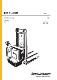
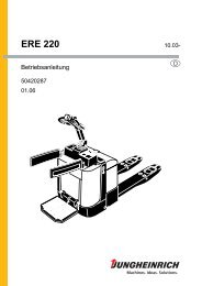
ISM Online Access Module08.11 -Operating instructionsG5121448705.13I D E N T ?+ mode
ForewordNotes to the operating instructionsThe safe operation of the ISM online access module requires the application ofexpertise as outlined in the present ORIGINAL OPERATING INSTRUCTIONS. Theinformation is presented in a precise and clear manner. The chapters are arrangedby letter and the pages are numbered continuously.The present operating instructions contain information only on the ISM accessmodule option. For truck related information, refer to the respective truck operatinginstructions.The ISM online access module option is subject to ongoing development. We reservethe right to alter the design, features and technical aspects of the equipment. Noguarantee of particular features of the ISM online access module should therefore beassumed from the present operating instructions.Safety notices and text mark-upsSafety instructions and important explanations are indicated by the followinggraphics:DANGER!Indicates an extremely hazardous situation. Failure to comply with this instruction willresult in severe irreparable injury and even death.WARNING!Indicates an extremely hazardous situation. Failure to comply with this instructionmay result in severe irreparable injury and even death.CAUTION!Indicates a hazardous situation. Failure to comply with this instruction may result inslight to medium injury.ZNOTEIndicates a material hazard. Failure to comply with this instruction may result inmaterial damage.Used before notices and explanations.toIndicates standard equipmentIndicates optional equipment05.13 EN3
CopyrightCopyright of these operating instructions remains with JUNGHEINRICH AG.<strong>Jungheinrich</strong> AktiengesellschaftAm Stadtrand 3522047 Hamburg - GermanyTel: +49 (0) 40/6948-0www.jungheinrich.com05.13 EN4
ContentsA General ................................................................................... 71 Displays and Controls.............................................................................. 72 Transponder types................................................................................... 82.1 Driver transponders ................................................................................. 82.2 Master transponders................................................................................ 82.3 Decommissioning transponders V.O.R Transponder .............................. 82.4 Engineer transponders ............................................................................ 92.5 Delivery transponders.............................................................................. 9B Operation ................................................................................ 111 Normal truck operation / preparing the truck for operation ...................... 111.1 Release the Emergency Disconnect switch ............................................ 111.2 Information shown in the display of the ISM online access module afterreleasing the emergency disconnect switch. ........................................... 121.3 Logging into the ISM online access module ............................................ 141.4 Truck status check................................................................................... 161.5 If an invalid driver transponder is produced............................................. 191.6 Switching the truck off ............................................................................. 201.7 Warehouse and system truck special feature.......................................... 212 Impact events .......................................................................................... 222.1 Impact event storage ............................................................................... 222.2 Impact event storage and display............................................................ 222.3 Impact event storage and display with truck crawl speed ....................... 232.4 Impact event storage and display with truck stop.................................... 243 Error displays........................................................................................... 254 Trucks that have been accessed using the V.O.R Transponder. ............ 264.1 Release the Emergency Disconnect switch ............................................ 264.2 Decommissioning the industrial truck ...................................................... 264.3 Restoring the truck to service after decommissioning ............................. 27C Gateway (GW 100) of the ISM online ..................................... 291 Technical Specifications .......................................................................... 291.1 Gateway Specifications (GW 100)........................................................... 291.2 Power Supply Unit Technical Specifications ........................................... 302 Data plate ................................................................................................ 313 Displays and Controls.............................................................................. 324 LEDs on Gateway of ISM online.............................................................. 335 Troubleshooting....................................................................................... 366 Gateway hold pattern (GW 100).............................................................. 3705.13 EN5
DServicing the ISM online components and the Gateway (GW100) ......................................................................................... 391 General.................................................................................................... 392 Cleaning .................................................................................................. 393 Working on the electrical system............................................................. 404 Used parts ............................................................................................... 405 Servicing and Inspection ......................................................................... 416 Maintenance checklist ............................................................................. 426.1 Maintenance Checklist - Electrical System.............................................. 4205.13 EN6
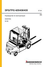
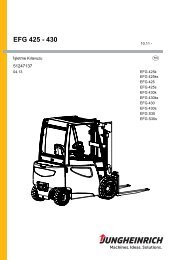
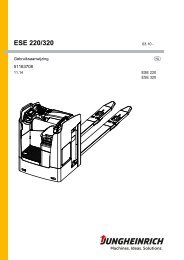
AGeneral1 Displays and ControlsI D E N T ?12+ mode3ItemDisplay or controlelementFunctionDisplays:– Information,1 Display – instructions,– impact events and– error messages– Switches off the truck.– Only if the "truck status check" isactivated:2 Red button "mode" – Prepare the truck for operation whenthe operator has detected damage.– Description of the truck status checksee "Truck status check" on page 163 Green button "+" – Prepares the truck for operation.05.13 EN7
2 Transponder typesZThe following transponder types are used to operate the JUNGHEINRICH ISMonline access module (truck management information system).2.1 Driver transpondersDriver transponders fulfil the following functions:– Assigning the transponder to an operator.– Access rights for selected trucks.2.2 Master transpondersThe master transponders fulfil the following functions:– Assigning the transponder to an operator (mainly warehouse managers).– Access rights for all fleet trucks.– Overriding crawl speed and truck stop function after improper use of the truck(shock).– Access rights for decommissioned trucks.2.3 Decommissioning transponders V.O.R TransponderDecommissioning transponders have the following functions:– Assigning the transponder to a member of staff (mainly warehouse managers).– Decommissioning a truck. The truck can no longer be restored to operational statuswith the driver transponder.– Resetting after using the V.O.R Transponder.05.13 EN8
2.4 Engineer transpondersEngineer transponders have the following functions:– Assigning the transponder to a member of staff / engineer.– Access rights for all fleet trucks.– Access rights for trucks when a V.O.R Transponder has been used.2.5 Delivery transpondersZA delivery transponder is glued to the access module when the truck is delivered. Thedelivery transponder has the following functions:– Access rights to the truck during delivery (before initial configuration).– The transponder can no longer be used when the access module has beenconfigured for the first time.The access module is configured initially in the management portal. After the initialconfiguration an authorisation list with at least one valid driver, master and engineertransponder is available in theISM online access module.– Access rights for the truck after disconnecting again in the management portal (noor empty authorisation list in the ISM) online access module.05.13 EN9
1005.13 EN
BOperation1 Normal truck operation / preparing the truck for operationZThe truck can only be prepared for operation using the ISM online access moduleafter initial configuration with a valid driver, master or engineer transponder.The following steps must be taken.1.1 Release the Emergency Disconnect switchZProcedure• Release the emergency disconnect switch.To release the emergency disconnect switch, referto the operating instructions.Depending on the initial configuration and thesoftware version of the access module, "<strong>IDENT</strong>?" or"CONNECT?" are displayed in the access-moduledisplay, see "Information shown in the display of theISM online access module after releasing theemergency disconnect switch." on page 12.I D E N T ?C O N N E C T ?+ modeZDepending on the truck, it may take a few seconds after releasing the emergencydisconnect switch for the "<strong>IDENT</strong>?" or "CONNECT?" display to light up.05.13 EN11
1.2 Information shown in the display of the ISM online access moduleafter releasing the emergency disconnect switch.Different information is shown in the access-module display after the emergencydisconnect switch has been released depending on the initial configuration and thesoftware version of the access module.The information shown in the access-module display and its meaning are describedin the following sections.1.2.1 Display of software version, lock number and CAN-bus versionRequirements– Emergency disconnect switch released, see"Release the Emergency Disconnect switch" onpage 11.– The display of the access module shows"<strong>IDENT</strong>?" or "CONNECT?".1Procedure• Press and hold down the red button "mode" (2)and the green button "+" (3) at the same time.• The access-module display (1) shows thefollowing information in turn:• The software version of the access module+ mode(Z: ...).• The software version of the data recorder(D: ...).3 2• The software version of the radio module(F: ...).• The lock number of the access module• The CAN-bus version set.• Release the red button "mode" (2) and the green button "+" (3).The display (1) of the access module shows "<strong>IDENT</strong>?" or "CONNECT?".05.13 EN12
1.2.2 Information shown in the display of the ISM online access module (up tosoftware version 02.0000 of the access module)Display<strong>IDENT</strong>?Meaning– Initial configuration of the ISM online access module was carriedout:– The truck can be prepared for operation using a valid driver,master or engineer transponder (authorisation list with atleast one valid driver, master and engineer transponder in theISM online access module).– The truck can be prepared for operation using the deliverytransponder.– Initial configuration of the ISM online access module was notcarried out (e. g. on delivery of the truck):– The truck can only be prepared for operation using thedelivery transponder (no or empty authorisation list in the ISMonline access module).1.2.3 Information shown in the display of the ISM online access module (fromsoftware version 03.0000 of the access module)Display<strong>IDENT</strong>?CONNECT?Meaning– Initial configuration of the ISM online access module was carriedout:– The truck can be prepared for operation using a valid driver,master or engineer transponder (authorisation list with at leastone valid driver, master and engineer transponder in the ISMonline access module).– The truck cannot be prepared for operation using the deliverytransponder.– Initial configuration of the ISM online access module was notcarried out (e. g. on delivery of the truck).– The truck can only be prepared for operation using the deliverytransponder (no or empty authorisation list in the ISM onlineaccess module).05.13 EN13
1.3 Logging into the ISM online access module1.3.1 Logging in with a valid driver, master and engineer transponderRequirements– Emergency disconnect switch released, see"Release the Emergency Disconnect switch" onpage 11.– IThe display of the access module shows"<strong>IDENT</strong>?“.Procedure• Place a valid transponder on the access module.• Access rights are checked by the access module.If the driver transponder is valid, a beep sounds.I D E N T ?+ mode- - c a r d ? -VJUNGHEINRICH+ mode05.13 EN14
1.3.2 Logging in with the delivery transponderZA delivery transponder is glued to the accessmodule when the truck is delivered. The deliverytransponder allows the truck to be madeoperational before the initial configuration.I D E N T ?C O N N E C T ?Requirements– Emergency disconnect switch released, see"Release the Emergency Disconnect switch" onpage 11.– The initial configuration of the access module wasnot carried out (no or empty authorisation list inthe ISM online access module).– The display of the access module shows"<strong>IDENT</strong>?“ (up to software version "02.0000“ of theaccess module).– The display of the access module shows"CONNECT?" (from software version "03.0000" ofthe access module).Procedure• Place the delivery transponder on the accessmodule.3• Access authorisation is checked by the accessmodule.If the delivery transponder is valid, a beep sounds. The access-module displayshows "ok?".• Press the green "+" key (3).The truck is now ready for operation.+ modeI D E N T ?C O N N E C T ?+ mode05.13 EN15
1.4 Truck status checkZA single-stage, two-stage or no truck status check on switching on the truck can beset in the management portal.1.4.1 No truck status checkRequirements– The truck status check is deactivated.Procedure• Place a valid transponder on the access module,see "Logging in with a valid driver, master andengineer transponder" on page 14.• The access module display shows "go!".The truck is now ready for operation.g o !+ mode05.13 EN16
1.4.2 Single-stage truck status checkZRequirements– Single-stage truck status check is activated.Procedureo k ?• Place a valid transponder on the access module,see "Logging in with a valid driver, master andengineer transponder" on page 14.The access module display shows "ok?". The trucknow cannot perform any travel or hydraulicoperations.• Determine the external condition of the truck within30 seconds after "ok?" appears in the display:3 2The access-module display changes from "ok?" to"<strong>IDENT</strong>?" if the truck's condition is not determinedwithin 30 seconds.g o !• If the truck is undamaged, press the green "+"button (3).It has been confirmed that the exterior of thetruck is in perfect condition.• If damage to the truck has been found, pressthe red button "mode" (2).It has been confirmed that the exterior of the truck is damaged.• The access module display shows "go!".The truck is now ready for operation.+ mode+ mode05.13 EN17
1.4.3 Two-stage truck status checkZThe two-stage truck status check when switching on the truck is only possible fromsoftware version "03.0000" of the access module.ZRequirements– Two-stage truck status check is activated.Procedure• Place a valid transponder on the access module,see "Logging in with a valid driver, master andengineer transponder" on page 14.The access module display shows "ok1?". Thetruck now cannot perform any travel or hydraulicoperations.• Determine the external condition of the truck within30 seconds after "ok1?" appears in the display:The access-module display changes from "ok1?"to "<strong>IDENT</strong>?" if the truck's condition is notdetermined within 30 seconds.• If the truck is undamaged, press the green "+"key (3).It has been confirmed that the exterior of thetruck is in perfect condition.• If damage to the truck has been found, pressthe red button (mode).It has been confirmed that the exterior of thetruck is damaged.• The access module display shows "ok2?".Trucks that support the "crawl speed" functionunder ISM Online can only be operated at thisspeed. The same applies for the hydraulic speeds.o k 1 ?+ mode3 2o k 2 ?+ mode3 2+ mode• Carry out a test run. In doing so, check the traveland hydraulic functions:• If no faults were found during the test run, press the green "+" button (3).It has been confirmed that the truck is in perfect working order.• If faults were found during the test run, press the red button "mode" (2).It has been confirmed that the truck is damaged.• The access-module display shows "go!".The truck is now ready for operation. The travel and hydraulic operations can beperformed with the maximum speeds which have been released for the truck.g o !05.13 EN18
1.5 If an invalid driver transponder is producedRequirements– Emergency Disconnect switch released, see"Release the Emergency Disconnect switch" onpage 11.Procedure• If an invalid driver transponder is held on theaccess module, the access module display shows"X<strong>IDENT</strong>??" for 30 seconds.The truck cannot be made operational with thistransponder. The truck will become operational if avalid driver transponder is produced.X I D E N T ? ?+ modeThe last point on the display shows a number to indicate the reason for not issuingthe release:– X<strong>IDENT</strong>01Transponder reading too short:– Hold the transponder on the access module for longer.– X<strong>IDENT</strong>02Driver transponder is blocked for a truck that has previously been accessed with aV.O.R Transponder.– Putting a truck back into service that has previously been blocked using a V.O.RTransponder .– X<strong>IDENT</strong>03Transponder no longer valid:– Extend transponder validity period in management portal.– X<strong>IDENT</strong>09Transponder can be read. No authorisation entered in access module for thistransponder:– Five short beeps sound in addition to the display message on the accessmodule.– Enter transponder in management portal for the truck.05.13 EN19
1.6 Switching the truck off1.6.1 Switching the truck off manuallyRequirements– Truck made operational.Procedure• Press the red button "mode" (2).The travel operation is complete. The truck isswitched off (exception: warehouse and systemtrucks). The ISM online access module displayshows "<strong>IDENT</strong>?". A new travel operation can bestarted.• Warehouse and system truck special feature:• To switch off the truck, press the red button"mode" (2) again.I D E N T ?+ mode2NOTEIf the truck does not switch off after press the red "mode" button again (2), this isprevented from doing so by the truck.For the operator to switch off the truck deliberately, the red "mode" button (2) mustbe pressed for at least 2 seconds.The truck is switched off.1.6.2 Switching the truck off automaticallyRequirements– The truck is now ready for operation-ZProcedure• After an adjustable timeout period during which no truck operations can beperformed, the truck shuts down automatically.Depending on the truck model, truck operations can be defined as the followingfunctions:- Travel operations,- Truck lifting and/or lowering operations,etc.The truck is switched off. The ISM online access module display shows "<strong>IDENT</strong>?". Anew travel operation can be started.05.13 EN20
1.7 Warehouse and system truck special featureZFor warehouse and system trucks, after a standbytimer is exceeded, "standby" is displayed.The truck cannot be operated in this status. Whenthe most recently used driver transponder is placedon the access module, the truck can be switched onagain. The truck status check is no longer carriedout.All other valid driver transponders can only startthe truck after it has been switched off, see"Switching the truck off" on page 20.s t a n d b y+ mode05.13 EN21
2 Impact eventsImproper operator actions are stored and can be displayed if required via a messageon the access module. The truck can respond in one of four ways.2.1 Impact event storageIn this configuration all impact events are stored. This does not affect the truck’s travelpattern.2.2 Impact event storage and displayIn this configuration the operator is informed that aserious impact event has occurred.The access module display shows an impactwarning "shock!" for 30 seconds. The message "go!"is then displayed.s h o c k !+ modeThe impact event is stored in the data recorder.This does not affect the truck’s drivingcharacteristics.g o !+ mode30 sec.05.13 EN22
2.3 Impact event storage and display with truck crawl speedIn this configuration the operator is informed that a serious impact event hasoccurred.The impact event is stored in the data recorder.After this type of impact event the access module display alternates between theimpact warning "shock!" and the prompt "M-<strong>IDENT</strong>".Trucks that support the "crawl speed" function under ISM online can only be operatedat this speed.After being switched off and on again with the driver or engineer transponder, thetruck can only be operated at crawl speed. The access module display continues toalternate between the impact warning "shock!" and the prompt "M-<strong>IDENT</strong>".Z The impact event and crawl travel can only be cancelled with a master transponder.Reset impact event / cancel crawl travel:Procedure• Press the red button "mode".The truck is switched off. The access moduledisplay alternates between "shock! – M-<strong>IDENT</strong> –<strong>IDENT</strong>?".• Place the master transponder on the accessmodule.The access module display shows the message"<strong>IDENT</strong>?" and a beep sounds. Crawl speed iscancelled.• The truck can be started up again with a validdriver transponder, see "Normal truck operation /preparing the truck for operation".s h o c k !+ modeM - I D E N T+ modeI D E N T ?+ mode05.13 EN23
2.4 Impact event storage and display with truck stopZIn this configuration the operator is informed that aserious impact event has occurred.After this type of impact event the access moduledisplay alternates between the impact warning"shock!" and the prompt "M-<strong>IDENT</strong>".The truck shuts down when an impact event isdetected.The truck can no longer be restored to operationalstatus with the driver or engineer transponder.The truck lock-out can only be cancelled using amaster transponder.s h o c k !+ modeM - I D E N T+ modeReset impact event / cancel truck lockout:Procedure• Place the master transponder on the accessmodule.The access module display shows the message"<strong>IDENT</strong>?" and a beep sounds.I D E N T ?+ mode• The truck can then be operated again with a validdriver transponder or engineer transponder, see"Normal truck operation / preparing the truck for operation" on page 11.05.13 EN24
3 Error displaysZTroubleshooting must only be performed by the manufacturer’s customer servicedepartment. The manufacturer has a service department specially trained for thesetasks.In order for customer services to react quickly and specifically to the fault, thefollowing information is essential:- Truck serial number- Error number from the display of the access module (if available)- Error description- Current location of truck.Error message "Er. 10X "The access module has an self-diagnostic feature which can be used to localise errorsources:– Er. 101Input/output error.Possible error source:– Faulty sensors.– Er. 102Internal error.Possible error source:– Software error, faulty internal hardware.– Er. 103Parameter error.Possible error source:– Inconsistent parameter setting, e.g. sensor limit 1 greater than sensor limit 2,standby timeout greater than truck timeout05.13 EN25
4 Trucks that have been accessed using the V.O.RTransponder.The trucks can be taken out of and returned to service using a valid V.O.RTransponder .4.1 Release the Emergency Disconnect switchZProcedure• Release the emergency disconnect switch.To release the emergency disconnect switch, referto the operating instructions.Depending on the initial configuration and thesoftware version of the access module, "<strong>IDENT</strong>?" or"CONNECT?" are displayed in the access-moduledisplay, see "Information shown in the display of theISM online access module after releasing theemergency disconnect switch." on page 12.I D E N T ?+ modeZDepending on the truck, it may take a few seconds after releasing the emergencydisconnect switch for the "<strong>IDENT</strong>?" or "CONNECT?" display to light up.4.2 Decommissioning the industrial truckProcedure• Place a valid V.O.R Transponder on the accessmodule.The truck is taken out of service with thedecommissioning transponder. The ISM onlineaccess module display shows "locked".l o c k e d+ mode05.13 EN26
4.3 Restoring the truck to service after decommissioning4.3.1 Truck returned to use with a V.O.R TransponderRequirements– Truck removed from use with a valid V.O.RTransponder, see "Decommissioning the industrialtruck" on page 26.Procedure• Place a valid V.O.R Transponder on the accessmodule.The truck is released again for operation. The ISMonline access module display shows "<strong>IDENT</strong>?".• The truck can be operated again with a valid drivertransponder, see "Normal truck operation /preparing the truck for operation" on page 11.l o c k e d+ modeI D E N T ?+mode05.13 EN27
4.3.2 Switching on a V.O.R Transponder truck with the master or engineertransponderZZA decommissioned truck can be released using amaster or engineer transponder.Requirements– Truck removed from use with a valid V.O.RTransponder, see "Decommissioning the industrialtruck" on page 26.Procedure• Place a valid master or engineer transponder onthe access module.Depending on the truck status check setting, thedisplay of the ISM online access module shows"ok?", "ok1?” or "go!".• Switching off the truck depending on the truckstatus check:• Switching on the truck with the truck statuscheck deactivated, see "No truck status check"on page 16.• Switching on the truck with the single-stagetruck status check deactivated, see "Singlestagetruck status check" on page 17.• Switching on the truck with the two-stage truckstatus check deactivated, see "Two-stage truckstatus check" on page 18.• The access module display shows "go!".The truck is now ready for operation.• Release the red button„mode“ (2) to switch off thetruck.The truck has been taken out of service. The ISMonline access module display shows "locked".After the truck has been restored to perfectworking order, the decommissioning of the truckmust be cancelled, see "Truck returned to use witha V.O.R Transponder" on page 27.l o c k e d+ modeo k 1 ?o k ?+ mode3 2g o !+ mode05.13 EN28
CGateway (GW 100) of the ISM online1 Technical Specifications1.1 Gateway Specifications (GW 100)ProcessorMain memoryBulk memoryOperating systemPower supplyPower consumptionPortsDimensionsAttachmentWeightSafety classElectromagneticcompatibility (EMC)Ambient temperatureRelative air humidityCommunicationIntel® Atom TM N270; 1.6 GHz512 MB2 GB FlashLinux15 V DC (12 V to 24 V) via 2.5 mm phone jackapprox. 13 W– Ethernet 1000-BaseT/100-BaseT/10-BaseTAutoswitch (RJ45 port) "LAN1"– Ethernet 100-BaseT/10-BaseT Autoswitch (RJ45port) "LAN2"– 2 x USB 2.0– Width: approx. 138 mm– Height: approx. 317 mm– Depth: approx. 138 mm– 4 screws (5 mm) to attach the Gateway– 2 screws (5 mm) for additional securing of theGateway2.4 kg (excl. power supply unit)IP52EN55022 Class B0 °C to 45 °C (in operation)5 % to 95 % (in operation), no thawing– Integrated GSM/GPRS module (quad-band)850 MHz / 900 MHz / 1800 MHz / 1900 MHz,Max. emission 2 W,Connection via FME male– Integrated narrow band module 433 MHz,Connection via SMA female– 6 LEDs for status displaysNOTEThe Gateway complies with the main protection requirements laid down in theCouncil Directive for the Approximation of the Laws of the Member States forElectromagnetic Compatibility 2004 / 108 / EG, as well as the Low Voltage Directive2006 / 95 / EG.05.13 EN29
1.2 Power Supply Unit Technical SpecificationsPower supply100 V AC to 240 V ACMains frequency50 Hz to 60 HzMaximum input current 0,7 AInput fuseInternal primary current fuse,inrush limitingLoad control ± 5 %Output response time 0.5 ms for 50% load change typical– Short-circuit protectionOutput fuse– Overvoltage protection– Overcurrent protectionSafety certificatesCB,UL, cUL, FCC, GS, CE, PSE, BSMI, RCM, LPSElectrical designSwitching flyback transformerDielectric resistivity 3000 VAC primary – secondaryLeakage current0,25 mA @ 2 pinEfficiency Energy Star Level V & ERP Level 2Electromagneticcompatibility (EMC)EN55022 Class BCurrent fluctuations EN61000-3-2.3Electromagneticinterference (EMI)EN61000-4-2,3,4,5,6,8,11Mean time between failure50000 calculated hours at 25 C according to MIL-HDBK-217FAmbient temperature 0 °C to 40 °C (in operation)Relative air humidity 20 % to 80 % (in operation), no thawingCooling:Convection cooling via surface– Width: approx. 88 mmDimensions– Height: approx. 50 mm– Depth: approx. 34 mmWeight186 g05.13 EN30
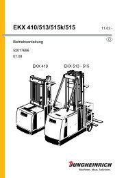
2 Data plate4 5 6 78TypTypeSerien-Nr.Serial no.TypennummerType numberSachnummerPart numberLAN1LAN2HerstellerManufacturerKW/BaujahrCalendar Week /Year of manufactureLieferanten-Nr.Supplier no.RevisionnummerRevision number91011121314Item Component Item Component4 Model name 10 Revision number5 Serial number 11 Ethernet address LAN16 Type number 12 Ethernet address LAN27 Part no. 13 Manufacturer8Calendar week / year ofmanufacture14 Manufacturer’s logo9 Supplier number05.13 EN31
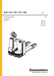
3 Displays and Controls15 16 17 18 19 20 21 22 23 24 25 26 27Item Description15 t "Main" LED16 t "RSP" LED17 t "From RSP" LED18 t "To RSP" LED19 t "Radio" LED20 t "GSM" LED21 t Port for the 433 MHz antenna "Gateway connection to truck"22 t Ethernet port LAN123 t Ethernet port LAN224 t USB port 125 t USB port 226 t Mobile radio antenna port27 t Power supply05.13 EN32
4 LEDs on Gateway of ISM onlineLEDcomponentMAIN (15)RSP (16)DisplayOFFFlashing GREEN:- 1 second on- 1 second offGREENREDOFFFlashing GREEN:- 1 second on- 1 second offFlashing red:- 1 second on- 1 second offGREENORANGEREDMeaning– Gateway not connected to themains.During operating phase:– "Maintask" software not started.During operating phase:– Normal operational status afterGateway is launched.– "Maintask" software is operational.During start-up phase (< 30 secondsafter switching the Gateway on):– LED lit during Gateway start up.During operating phase:– "Maintask" software not operational.During operating phase:– "Maintask" software has detected aninternal error.During start-up phase (< 30 secondsafter switching the Gateway on):– LED not lit during Gateway start up.During operating phase:– Connection software to transferserver not started.During operating phase:– Normal operational status afterGateway is launched.– Connection software to transferserver operational.During operating phase:– Communication error with thetransfer server.During operating phase:– Connection software to transferserver not operational.During operating phase:– Gateway receives data from transferserver.During operating phase:– Gateway sends data to transferserver.05.13 EN33
LEDcomponentFrom RSP (17)To RSP (18)Radio (19)DisplayOFFORANGEOFFORANGEOFFGREENORANGEREDMeaningDuring start-up phase (< 30 secondsafter switching the Gateway on):– LED not lit during Gateway start up.During operating phase:– No data present in the Gateway thatneeds to be sent to the truck.– No data present in the Gateway thatneeds to be processed by theGateway.During operating phase:– Data present in the Gateway thatneeds to be sent to the truck.– Data present in the Gateway thatneeds to be processed by theGateway.During start-up phase (< 30 secondsafter switching the Gateway on):– LED not lit during Gateway start up.During operating phase:– No data present in the Gateway thatneeds to be sent to the transferserver.During operating phase:– Data present in the Gateway thatneeds to be sent to the transferserver.During start-up phase (< 30 secondsafter switching the Gateway on):– LED not lit during Gateway start up.During operating phase:– Radio connection to truck notoperational.– Radio connection to truckoperational.– Gateway receives data from thetruck.– Gateway sends data to the truck.05.13 EN34
LEDcomponentGSM (20)DisplayOFFFlashing ORANGE:- 1 second on- 1 second offFlashing ORANGE:- 1 second on- 3 seconds offORANGEMeaningDuring start-up phase (< 30 secondsafter switching the Gateway on):– LED not lit during Gateway start up.During operating phase:– Radio connection to transfer servernot operational.After start-up phase (< 5 minutes afterswitching the Gateway on):– Mobile radio network login notcompleted.During operating phase:– Connection established betweenGateway and mobile radio network.During operating phase:– Gateway sends data to transferserver.– Gateway receives data from transferserver.05.13 EN35
5 TroubleshootingZThis chapter enables the user to identify and rectify basic faults. When trying to locatea fault, adhere to the remedial action in the order shown in the table.If, after carrying out the following remedial action, the Gateway cannot be restoredto operation or if a fault is indicated by other LEDs lighting up, contact themanufacturer’s service department. Troubleshooting must only be performed bythe manufacturer’s customer service department. The manufacturer has a servicedepartment specially trained for these tasks.LEDcomponentMAIN (15)RSP (16)From RSP (17)To RSP (18)Radio (19)GSM (20)MAIN (15)RSP (16)DisplayOFFGREENREDGREENRemedy– Check Gateway power supply.– Disconnect the Gateway powersupply for at least 30 seconds (e. g.remove the mains connector, deenergisethe socket, ...).– Restore Gateway power supply.During operating phase (> 30 secondsafter switching the Gateway on):– Disconnect the Gateway powersupply for at least 30 seconds (e. g.remove the mains connector, deenergisethe socket, ...).– Restore Gateway power supply.– Disconnect the Gateway powersupply for at least 30 seconds (e. g.remove the mains connector, deenergisethe socket, ...).– Restore Gateway power supply.During operating phase (> 30 secondsafter switching the Gateway on):– Disconnect the Gateway powersupply for at least 30 seconds (e. g.remove the mains connector, deenergisethe socket, ...).– Restore Gateway power supply.05.13 EN36
6 Gateway hold pattern (GW 100)05.13 EN37
3805.13 EN
DServicing the ISM online components andthe Gateway (GW 100)1 GeneralThe checks and servicing operations contained in this chapter must be performed inaccordance with the maintenance checklist service intervals.Maintenance personnelThe ISM online components and the Gateway (GW 100) should only be serviced andrepaired by the manufacturer's specialist customer service personnel who have beentrained to do this. We therefore recommend that you enter into a maintenancecontract with the manufacturer’s local sales office.2 CleaningCAUTION!Risk of damage to the ISM online components and the Gateway (GW 100)Cleaning the ISM online components and the Gateway (GW 100) with water candamage the electrical system.ISM Do not clean the online components and Gateway with water.ISM Clean the online components and the Gateway with weak suction orcompressed air (use a compressor with a water trap) and a non-conductive, antistaticbrush.05.13 EN39
3 Working on the electrical systemWARNING!Electrical current can cause accidentsMake sure the ISM online components are de-energised before starting work onthem. The capacitors in the truck must be completely discharged. The capacitors arecompletely discharged after approximately 10 minutes. Before starting maintenanceon the electrical system:Only suitably trained electricians may work on the ISM online components.Before working on the electrical system, take all precautionary measures to avoidelectric shocks.Park the truck securely (see relevant section in truck's operating instructions)Disconnect the batteryRemove any rings, metal wristbands etc.WARNING!Electrical current can cause accidentsMake sure the Gateway (GW 100) is de-energised before starting work on it. Thecapacitors in the Gateway must be completely discharged. The capacitors arecompletely discharged after approximately 10 minutes. Before starting maintenanceon the electrical system:Disconnect the mains supply before working on the Gateway.Remove any rings, metal wristbands etc.4 Used partsCAUTION!Used parts are an environmental hazardUsed parts must be correctly disposed of in accordance with the valid environmentalprotectionregulations.Note the safety regulations when handling these materials.05.13 EN40
5 Servicing and InspectionWARNING!Lack of maintenance can result in accidentsFailure to perform regular servicing can lead to the failure of trucks with ISM onlinecomponents and poses a potential hazard to personnel and equipment. This alsoapplies to the Gateway (GW 100).Thorough and expert servicing is one of the most important requirements for thesafe operation of the industrial truck with ISM online components. This also appliesto the Gateway (GW 100).The application conditions of an industrial truck have a considerable impact oncomponent wear of the ISM online components. The following service intervals arebased on single-shift operation under normal operating conditions. They must bereduced accordingly if the equipment is to be used in conditions of extreme dust,temperature fluctuations or multiple shifts.NOTEThe manufacturer recommends an on-site application analysis to determine themaintenance intervals required to avoid damage caused by wear.The following maintenance checklist lists the activities to be performed and therespective intervals to be observed. Maintenance intervals are defined as:ZW = Every 50 service hours, at least weeklyA = Every 500 service hoursB = Every 1000 service hours, or at least annuallyC = Every 2000 service hours, or at least annuallyt = Standard maintenance intervalk =Cold store maintenance interval (in addition to standard maintenanceinterval)"W" maintenance-interval activities should be performed by the operatingcompany.05.13 EN41
6 Maintenance checklist6.1 Maintenance Checklist - Electrical SystemTruck Management Information System "ISM"Truck Management Information System "ISM" W A B C1 Test access module, check for damage and make sure it is secure. t2 Check data recorder is secure and check for damage. t3 Check radio module is secure and check for damage. t4 Check wiring is secure and check for damage. tGateway (GW 100)Gateway (GW 100) W A B C1 Test Gateway, check for damage and make sure it is secure. t2Test power supply unit, check for damage and make sure it issecure.t3 Check antenna is secure and check for damage. t4 Check wiring is secure and check for damage. t05.13 EN42