- Page 3 and 4: STANDARD TERMS ANDCONDITIONS OF SAL
- Page 5 and 6: Specifications &StandardsAIRPORT LI
- Page 7 and 8: AIRPORT LIGHTING PRODUCTSApplicatio
- Page 9 and 10: 1ZZ23YZY45Z6ZSection 4 — Power &
- Page 11 and 12: PRO III RCL/TDZRunway Centerline Li
- Page 13 and 14: PRO III RCL/TDZRunway Centerline Li
- Page 16 and 17: 7.94(202)Outline DrawingLENSLENSgas
- Page 18 and 19: Outline Drawings11.94 (303) DIADime
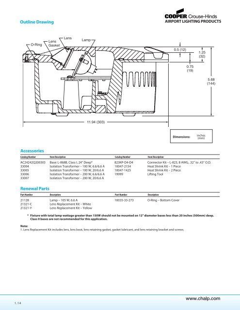
- Page 20 and 21: Outline DrawingLENS11.94 (303) DIAO
- Page 24 and 25: NotesRunway and Taxiway Inset Light
- Page 26 and 27: Outline DrawingDimensions:inches(mm
- Page 28 and 29: Installation DrawingsRTEL-850D1-B11
- Page 30 and 31: Typical Photometric Data5,000 CD MI
- Page 32 and 33: Installation DrawingsATL-850E1-BDim
- Page 34 and 35: Outline Drawing11.94 (303) DIAOPTIC
- Page 36 and 37: Typical Photometric Data20 CD AVERA
- Page 38 and 39: Typical Photometric Data100 CD AVER
- Page 40 and 41: Typical Photometric Data:1212Vertic
- Page 42 and 43: Typical Photometric Data12VERTICAL
- Page 44 and 45: Typical Photometric DataVERTICAL AN
- Page 46 and 47: Typical Photometric Data200100VERTI
- Page 48 and 49: Typical Photometric Data100 CD MINI
- Page 50 and 51: Typical Photometric Data1510100 CAN
- Page 52 and 53: Typical Photometric Data125 CD MIN.
- Page 54 and 55: Typical Photometric Data9025 CD2 CD
- Page 56 and 57: Outline Drawings12˝ Fixture8˝ Fix
- Page 58 and 59: Outline Drawing TOL: 21078.75(19)11
- Page 60 and 61: SECTION 2Runway & TaxiwayElevated L
- Page 62 and 63: Installation DrawingsStake Mounted
- Page 64 and 65: Installation DrawingsBase Mounted H
- Page 66 and 67: Installation DrawingsBase Mounted H
- Page 68 and 69: Outline DrawingTypical Photometric
- Page 70 and 71: Outline DrawingLEnS CLIP, P/n50121P
- Page 72 and 73:
Typical Photometric Data1,000 CD MI
- Page 74 and 75:
Outline DrawingTypical Photometric
- Page 76 and 77:
Installation DrawingsStake Mounted
- Page 78 and 79:
SECTION 3Approach &Navigational Aid
- Page 80 and 81:
Installation InformationNote:See Ad
- Page 82 and 83:
Dimensions:Instruction Manualinches
- Page 84 and 85:
Outline DrawingsFTS 8 Series Co-Mou
- Page 86 and 87:
Outline DrawingsFRONT VIEW19(482.6)
- Page 88 and 89:
Photometric Data20ELEVATION vs EFFE
- Page 90 and 91:
Photometric Data2,000 CD MINIMUM1,0
- Page 92 and 93:
Outline DrawingInstruction Manual:
- Page 94 and 95:
Photometric Data1000 CD MIN.2000 CD
- Page 96 and 97:
Outline DrawingInstruction Manual:
- Page 98 and 99:
Typical Photometric Data1000 CD MIN
- Page 100 and 101:
NotesApproach & Navigational AidsCr
- Page 102 and 103:
Typical Photometric Data10000 CD MI
- Page 104 and 105:
NotesApproach & Navigational AidsCr
- Page 106 and 107:
Technical DataTable ACompliance App
- Page 108 and 109:
Application Notes• Only the mount
- Page 110 and 111:
Installation DrawingsRigid Installa
- Page 112 and 113:
SECTION 4Power & ControlEquipmentPo
- Page 114 and 115:
REmOTELOCALCOnTROLsWiTCH5OFF4132COn
- Page 116 and 117:
LOCALCONTROLSWITCHOutline Drawing!D
- Page 118 and 119:
LOCALCOnTROLsWiTCH!Outline Drawingd
- Page 120 and 121:
dO nOT PuLL On sHEET mETAL!Outline
- Page 122 and 123:
PowertracOutline Drawing128.0˝ (32
- Page 124 and 125:
Outline DrawingFRONT VIEW30kw, 60Hz
- Page 126 and 127:
Outline DrawingFRONT VIEWSIDE VIEW2
- Page 128 and 129:
Outline DrawingTOP VIEW32.2(818)FRO
- Page 130 and 131:
43 Digital Display of Line VoltageD
- Page 132 and 133:
LAHSO System DescriptionThe lightin
- Page 134 and 135:
NotesPower & Control EquipmentCrous
- Page 136 and 137:
Outline DrawingsSuggestedConduit En
- Page 138 and 139:
SPCSeries Plug CutoutType S-1 (MODE
- Page 140 and 141:
Adaptable and flexibleInnovative de
- Page 142 and 143:
Technical DataTypical Transformer P
- Page 144 and 145:
CKSSecondary Connector KitsComplian
- Page 146 and 147:
CACable AssembliesCompliances: FAA
- Page 148 and 149:
SECTION 5GuidanceSignsAPRONAPRONZ X
- Page 150 and 151:
Technical DataAirside Guidance Sign
- Page 152 and 153:
Installation DetailsElbow Mounting
- Page 154 and 155:
Technical DataInstruction Manual: 9
- Page 156 and 157:
Installation DetailsElbow Mounting
- Page 158 and 159:
Technical DataInstruction Manual: 2
- Page 160 and 161:
Installation DetailsElbow Mounting
- Page 162 and 163:
DMSDistance Marker SignCompliances:
- Page 164 and 165:
SECTION 6Tools& MarkersTools & Mark
- Page 166 and 167:
Tools10036-39 Impact Driver20047 Co
- Page 168 and 169:
NotesTools and MarkersCrouse-HindsR
- Page 170 and 171:
25684-1 60285 62245Floor FlangeFL97
- Page 172 and 173:
Installation DrawingsSoil Anchor Mo
- Page 174 and 175:
SECTION 7AirportLight BasesAirport
- Page 176 and 177:
Catalog Specification Reference Shi
- Page 178 and 179:
Dimensional Information* Typical fo
- Page 180 and 181:
SIB-8Shallow Inset Light Base - 8˝
- Page 182:
852C21YG...........................