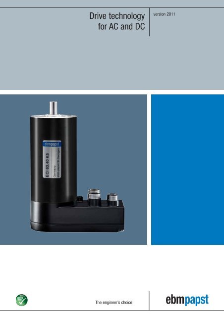
Drive technology for AC and DC
Drive technology for AC and DC
Drive technology for AC and DC

You also want an ePaper? Increase the reach of your titles
YUMPU automatically turns print PDFs into web optimized ePapers that Google loves.
<strong>Drive</strong> <strong>technology</strong><strong>for</strong> <strong>AC</strong> <strong>and</strong> <strong>DC</strong>version 2011The engineer’s choice
VARIODRIVEIn<strong>for</strong>mationTable of contentsIn<strong>for</strong>mation 4– The company– GreenTech: The Green Company– Motor <strong>technology</strong>VARIODRIVE 13– EC external rotor motorVARIODRIVE Compact 25– EC Compact motor– EC Compact gear motorVario<strong>Drive</strong> C 55– Size 084– Size 112– Size 150ECI motor 75– EC internal rotor motor– EC compact motor– EC gear motor– Brake, sensor, accessoriesBG motorECI motorVario<strong>Drive</strong> C VARIODRIVE CompactBG motor 103– BG 4310– BG 4320– BG 4340BCI motorBCI motor 111– <strong>DC</strong> motor– <strong>DC</strong> gear motor– Brake, sensors<strong>AC</strong> motors 135– <strong>AC</strong> shaded-pole motors– <strong>AC</strong> capacitor motors– <strong>AC</strong> gear motorsSpecifications 147– Guidelines– Definitionsebm-papst representatives & subsidiaries 1583<strong>AC</strong> motorsSpecificationsRepresentatives
Company profile: ebm-papstThe entire scope of ventilation <strong>and</strong> drive <strong>technology</strong>: this is the world of ebm-papst. More than 10,000 people – inGermany <strong>and</strong> throughout the world – develop, produce <strong>and</strong> sell our motors <strong>and</strong> fans. Our global presence <strong>and</strong>unique range of product’s based on a quality st<strong>and</strong>ard that surpasses all others have made us what we are: theworld market leader in motors <strong>and</strong> fans. Expertly knowing what our customers need <strong>and</strong> incessantly strivingto arrive at the perfect application solution <strong>for</strong> a wide variety of different industries is what determines our dailywork. Those who know us know the high st<strong>and</strong>ards we apply to our work <strong>and</strong> know our creed: to be as closeto our customers as possible <strong>and</strong> to simply be the best in terms of innovation <strong>and</strong> reliability.Our location in St. Georgen4
VARIODRIVEIn<strong>for</strong>mationLeft:Our headquarters in MulfingenRight:Our location in L<strong>and</strong>shutVARIODRIVE CompactOur history – Our driveRooted in ebm, PAPST <strong>and</strong> mvl, the three leading innovators in thedevelopment <strong>and</strong> production of motors <strong>and</strong> fans, ebm-papst hasestablished itself as the world market leader. Now as ever, our legendaryinventive spirit shines through in products that set st<strong>and</strong>ards in manysegments of industry worldwide. We are proud to say that despite difficultcompetition, our per<strong>for</strong>mance has always been exemplary <strong>and</strong> outst<strong>and</strong>ing– in business, in our personal relationship with our customers, <strong>and</strong> ofcourse with respect to <strong>technology</strong> <strong>and</strong> engineering. For decades, we havecontributed to the world of air <strong>technology</strong> <strong>and</strong> drive engineering withsmall revolutions <strong>and</strong> large milestones.To maintain this advantage in skills <strong>and</strong> knowledge to get maximumquality <strong>and</strong> thus the highest degree of customer satisfaction, ouremployees around the world put their passion <strong>and</strong> dedication to work<strong>for</strong> you.Passionately involved in R&DOur catalogues just list the results of our incessant ef<strong>for</strong>ts in R&D:products of highest quality <strong>and</strong> reliability. After all, it is our passion toconstantly try something new <strong>and</strong> improve what we have. In doing so,we take advantage of the latest development methods <strong>and</strong> state-ofthe-art<strong>technology</strong> <strong>and</strong> invest quite heavily in R&D facilities. Best of all,though, we rely on excellently trained <strong>and</strong> skilled engineers <strong>and</strong>technicians to be at your service in R&D <strong>and</strong> Sales & Distribution.Producing <strong>and</strong> safeguarding high-quality products <strong>and</strong> servicesThis is our promise without any compromise. Whether produced in one ofour six factories in Germany or one of our eleven international productionsites, our products always have the same high level of quality. This qualitycontrol is something you can definitely rely on! And this across all levelsof production <strong>and</strong> throughout all processes: providing consultation tocustomers, development, material selection through to picking certified,choice suppliers <strong>and</strong> on to the production of parts <strong>and</strong> final delivery. Ontop of this, our products have to numerous tests under all realisticoperating conditions: continuous stress test, salt spray test, vibration test,or the precision noise measurement laboratory , just to mention a few.And the product gets clearance <strong>for</strong> serial productiononly after all the desired characteristicshave been determined to be just right.Environmental care is another priority withebm-papst. This is why we have developedour product line in EC <strong>technology</strong>, which makes<strong>for</strong> very low power consumption. Due to ourmanufacturing philosophy, there is absolutefocus on environmental care in production,recycling, <strong>and</strong> waste disposal.Global DomesticIn order to be the specialist <strong>for</strong> customisedsolutions throughout the world, you need strongpartners. Global Domestic – i.e. being presentall over the world <strong>and</strong> being a national companyin each individual country – is how we haveestablished ourselves in all important marketsaround the globally with our successful subsidiaries.And so you will always find ebm-papstclose to home, speaking your language, <strong>and</strong>knowing the dem<strong>and</strong>s of your markets.Moreover, our worldwide production allianceserves as a basis <strong>for</strong> competitive pricing. Ourglobal services <strong>and</strong> logistic’s, i.e. IT networking,safeguard short reaction times <strong>and</strong> just-in-timedelivery.All our ef<strong>for</strong>ts are documented in a comprehensivequality management system, both <strong>for</strong> products<strong>and</strong> services. Being certified as compliantwith the tough requirements of the internationalst<strong>and</strong>ards DIN EN ISO 9001, ISO/TS 16949-2<strong>and</strong> of st<strong>and</strong>ard DIN EN ISO 14001 is just oneseal of approval we have received <strong>for</strong> ourunceasing ef<strong>for</strong>ts to provide only the bestquality products <strong>and</strong> services.5Vario<strong>Drive</strong> CECI motorBG motorBCI motorRepresentatives Specifications <strong>AC</strong> motors
Sustainability is at the centre of ourthoughts <strong>and</strong> actions. Out of conviction!Eco-friendliness <strong>and</strong> sustainability have always been at the core of our thoughts <strong>and</strong> actions. For decades, we have workedaccording to the simple but strict creed of our co-founder Gerhard Sturm: “Each new product we develop has to be betterthan the last one in terms of economy <strong>and</strong> ecology.” GreenTech is the ultimate expression of our corporate philosophy.
ECI motorVario<strong>Drive</strong> CBG motorBCI motorVARIODRIVE CompactVARIODRIVEIn<strong>for</strong>mationGreenTech is pro-active development.Even in the design phase, the materials <strong>and</strong> processes we use are optimised<strong>for</strong> the greatest possible eco-friendliness, energy balance <strong>and</strong> –wherever possible – recyclability. We continually improve the material<strong>and</strong> per<strong>for</strong>mance of our products, as well as flow <strong>and</strong> noise characteristics.At the same time, we significantly reduce energy consumption.Close co-operation with universities <strong>and</strong> scientific institutes <strong>and</strong> the professorshipwe endow in the area of power engineering <strong>and</strong> regenerativeenergies allows us to benefit from the latest research findings in thesefields – <strong>and</strong> at the same time ensure highly qualified young academics.GreenTech is acknowledged <strong>and</strong> certified.Every step in our chain of production meets the stringent st<strong>and</strong>ards ofenvironmental specialists <strong>and</strong> the public. The 2008 Environmental Prizeof Baden-Wuerttemberg, the Green Award 2009, the Energy EfficiencyAward 2009 of the dena – to give just a few examples – testify to this.The environmental advantage gained in the per<strong>for</strong>mance of the productsdeveloped from our GreenTech philosophy can also be measured in thefulfilment of the most stringent energy <strong>and</strong> environmental st<strong>and</strong>ards.In many instances, our products are already well below the thresholdsenergy legislation will impose a few years from now – several times over.GreenTech is eco-friendly production.GreenTech also st<strong>and</strong>s <strong>for</strong> maximum energy efficiency in our productionprocesses. There, the intelligent use of industrial waste heat <strong>and</strong> groundwatercooling, photovoltaics <strong>and</strong>, of course, our own cooling <strong>and</strong> venti -lation <strong>technology</strong> are of the utmost importance. Our most modern plant,<strong>for</strong> instance, consumes 91% less energy than currently specified <strong>and</strong>required. In this way, our products contribute to protecting the environment,from their origin to their recyclable packaging.Our customers profit from this every day.The heart of GreenTech is future-oriented EC <strong>technology</strong> from ebmpapst.The EC <strong>technology</strong> at the core of our most efficient motors <strong>and</strong>fans allows efficiency of up to 90%, saves energy at a very high level,significantly extends service life <strong>and</strong> makes our products maintenancefree.These values pay off not only <strong>for</strong> the environment, but every cent alsopays off <strong>for</strong> the user! All ebm-papst products – even those <strong>for</strong> whichGreenTech EC <strong>technology</strong> does not (yet) make sense from an applicationviewpoint – feature the greatest possible connection of economy <strong>and</strong>ecology.7Representatives Specifications <strong>AC</strong> motors
Motor <strong>technology</strong>Electronic motor commutationTo produce a motor torque, the field windings in the stator of the motorreceive a current. The resulting magnetic field reacts against the permanentmagnetic field of the rotor, generating a torque.In order to ensure that the rotor continuously rotates, the current in thewinding must be commutated. In conventional <strong>DC</strong> motors, the commutationnecessary <strong>for</strong> constant rotation of the armature is achieved mechanicallyusing a commutator <strong>and</strong> brushes. Thanks to modern semi-conductor <strong>technology</strong>,this mechanical commutation can be replaced by a non-contacting,electronic circuit.The magnet is in the <strong>for</strong>m of a rotor, <strong>and</strong> field windings that are distributedover the circumference of the stator are each connected to the voltagesource via one or more transistor switches. The transistor switches arecontrolled depending on the position of the magnetic rotor. For determiningthe position of the rotor, Hall effect sensors are used-, one or more rotorposition encoders positioned on the printed circuit board of the motor. Suchmotors are referred to as electronically commutated motors, in short ECmotors.The most distinct advantages of this type ofmotor: The EC motor sidesteps the disadvantagesassociated with the mechanical commutatorsuch as, commutator wear, brush friction,accumulation of dust due to abrasion, noises,starting difficulties due to corrosion of thecommutator segments <strong>and</strong> high-frequencyinterference caused by sparking.A distinguishing feature of the EC motor is itscompact size. Furthermore, the commutationelectronics can be equipped at comparably lowcost with an electronic control unit <strong>for</strong> maintaininga constant speed. The rotor position sensorsare additionally used <strong>for</strong> determining theactual speed. The considerably better servicelife values in comparison to the brush <strong>DC</strong>motors are also a major feature.8
VARIODRIVE CompactVARIODRIVEIn<strong>for</strong>mationMotor principlesThe ebm-papst EC range is based on two types of motor that have completelydifferent contruction features: on the one h<strong>and</strong>, the external rotormotors of the VARIODRIVE, VARIODRIVE Compact <strong>and</strong> Vario<strong>Drive</strong> C series;on the other, the internal rotor motors of the ECI, ECI Compact <strong>and</strong> BGseries.Each of these 6 series has an independent per<strong>for</strong>mance profile that is notonly underlined by highly sophisticated motor characteristics but is also ofeconomic significance. Detailed in<strong>for</strong>mation can be found in the introductorypassages of the individual product groups.Another classifying feature <strong>for</strong> distinguishing between the internal <strong>and</strong>external rotor motor design is the basic structure of the winding <strong>and</strong> theactive motor parts. Here, it is primarily the number of grooves of the stator<strong>and</strong> the number of pole pairs of the magnet rotor that are of key significance.For the activation of the motors, we can make a basic distinction betweenthe simpler variant of block commutation <strong>and</strong> the more elaborate one withsinus commutation. For block commutation, the number of switching pulsesresults from the number of phases of the winding <strong>and</strong> the number ofpoles of the rotor. For sinus commutation, the commutation of the currentin all 3 winding phases is continuous. In this process, based on a continuoussine/cosine sensor signal, the 3 winding phases are energised by ahigh-frequency PWM modulation with sinusoidal phase-shifted currents <strong>for</strong>each, which enables smoother running behaviour <strong>and</strong> lower speeds.The external rotor motorIn external rotor motors, the bell-shaped rotor isfirmly connected to the shaft <strong>and</strong> revolvesaround the stationary stator. The motor flange isextended axially to support the stator with windings<strong>and</strong> the printed circuit board. Magneticfield sensors (Hall ICs) in the main field are usedto determine the rotor position. Compared to theinternal rotor motor, the magnets are fixed on agreater diameter providing not only a largermagnetic volume but also a concentration ofmagnetic flux to the stator inside. Furthermore,the same electromagnetic <strong>for</strong>ce <strong>and</strong> the greaterair gap diameter result in a higher torque.BCI motorBG motorECI motorVario<strong>Drive</strong> CExternal rotor motorBall bearingsHall ICStatorRotor with motor shaftMagnet9Representatives Specifications <strong>AC</strong> motors
Motor <strong>technology</strong>The internal rotor motorThe magnets of the internal rotor motor aresituated directly on the shaft together with a ferromagneticbushing to close the magnetic circuit.The stator lamination in the housing enablesexcellent cooling of the winding. The bearingsare situated in both flanges, flush-fitted tothe housing. The use of high-energy magneticmaterials guarantees full utilisation of the physicaldimensions. Magnetic sensors in the mainfield or in the field of a sensor magnet are usedto determine the rotor position. Internal rotormotors are more suitable than external rotor motors <strong>for</strong> functional drives.The low moment of inertia of the small, internal rotor enables a quickchange of speed <strong>and</strong> direction of rotation. Thanks to specially selectedmaterials, an extremely high power density can be achieved also in combinationwith miniaturised integrated electronics. In comparison to theexternal rotor motor, a higher protection class is also possible. Due to thetwo usable shaft ends, internal rotor motors provide greater versatility <strong>for</strong>the application of additional system or functional elements, e.g. brakes orencoders or tacho-generators <strong>for</strong> speed sensing <strong>and</strong> motor control.Versions with B-sided completely integrated 4-quadrant speed controloperating electronics are available off the shelf, ready to be connected.Internal rotor motorControl electronicsSensor magnetBall bearingStatorWindingMain magnetMotor housingMotor shaft10
VARIODRIVE CompactVARIODRIVEIn<strong>for</strong>mationThe mechanical motor commutationIn permanent magnet direct current motors, the principle of the currentcarryingwire loop in the magnetic field, on which an electromagnetic<strong>for</strong>ce works, is implemented directly. In motors of this type, the currentsupply to the rotating rotor windings <strong>and</strong> the reversal (commutation) ofthe current take place mechanically using what are called carbon brushes.These contact elements consist of a low-friction graphite materialwith copper mixed in to improve the conductivity. To transmit the requiredcurrents safely <strong>and</strong> reliably, these contact elements are pressed againstthe commutator by spring pre-tension. When the supply voltage is switchedon, a current flows through the winding via the two carbon brushes<strong>and</strong> the armature starts turning. Due to the resulting rotation <strong>and</strong> the splitof the commutator into many parts, the necessary conversion of the currentin the rotor winding takes place automatically, <strong>and</strong> a continuous rotationresults.Brush-commutated direct current motors (<strong>DC</strong>motors) feature outst<strong>and</strong>ing efficiency <strong>and</strong> ahigh start-up torque. Thus they are particularlywell suited <strong>for</strong> applications that need a highstart-up torque or good dynamics in short-termoperation. The easily described operating per<strong>for</strong>mancealso allows brush motors to be operatedin a wide speed range by simply changingthe applied supply voltage. There<strong>for</strong>e, they areof interest as a simple, powerful <strong>and</strong> robustdrive solution <strong>for</strong> a wide variety of applications.Vario<strong>Drive</strong> CECI motorBG motor<strong>DC</strong> motorCarbon brushCollectorInterference suppression componentsLaminated rotorWindingPermanent magnetMotor housingBall bearingMotor shaftBCI motor<strong>AC</strong> motorsSpecifications11Representatives
Motor <strong>technology</strong>The KM capacitor motorKM motors are 2- or 4-pole single-phase asynchronousmotors with a main winding <strong>and</strong> anauxiliary winding. To generate a rotary field, theoperating capacitor, which is switched in serieswith the auxiliary winding, attains a phase shift ofthe main <strong>and</strong> auxiliary winding. Compared to <strong>AC</strong>shaded-pole motors, the KM motors feature betterefficiency <strong>and</strong> a higher start-up torque. Thismotor family includes a total of three differentmodels, one with open housing (IP00), anotherwith semi-open (IP20) <strong>and</strong> another with closedmotor housing.Facts <strong>and</strong> figures– Power range (depending on the motor packageheight <strong>and</strong> number of poles): rated outputup to 300 watts, rated torque up to 70 NcmAn extension of the power range is possible<strong>for</strong> short-time operation (S2)– Nominal voltage/frequency: 230V / 50Hz(Adaptation of the motor winding possible <strong>for</strong>other voltages <strong>and</strong> frequencies,e.g. 115V/60Hz)– Direction of rotation: clockwise (also suitable<strong>for</strong> counter-clockwise rotation if current flowis changed)– Insulation material class F (VDE/EN)– Bearing system with two ball bearings– Shaft diameter: 8mm (optionally, 10mm or12mm possible)– <strong>Drive</strong>-side shaft end: 25mm (up to 300mm possible <strong>for</strong> custom applications)– Mounting position: any (longer service life <strong>for</strong> horizontal shaft)– Various customer-specific designs available on requestApplication areas– <strong>Drive</strong> motor <strong>for</strong> gearbox (including spur, planetary <strong>and</strong> worm gear units)– Tangential fans (e.g. underfloor convection heating)– Centrifugal <strong>and</strong> axial fans (e.g. exhaust gas blowers)– Circulation blower <strong>for</strong> hot air with impeller > 150mm (including ovens <strong>and</strong> other commercialapplications)– <strong>Drive</strong> motor <strong>for</strong> pumps (membrane, gear, submersible circulation <strong>and</strong> recirculating pumps,condensers <strong>and</strong> compressors)– Heating engineering in solid fuel burners (including exhaust blowers, screw drives <strong>for</strong> conveying heating pellets, wood chips or combustion products)– Locking systems <strong>and</strong> door/gate drives (garage door <strong>and</strong> roll-down gate drives, etc.)– Polishing <strong>and</strong> grinding machines– Medical applications (centrifuges, lifting devices such as adjustable operating tables, massagers etc.)– Office equipment (e.g. postage meters, money counting <strong>and</strong> billing machines, file shredders,paper shredders or copiers)– Conveying <strong>and</strong> h<strong>and</strong>ling equipment (keg pumps, filling systems, single-roll drives <strong>for</strong> conveyorbelts etc.)– Packaging machines (binding machines, shrink wrap machines, etc.)– Food <strong>and</strong> food service machines (ice crushers, cutting machines, beverage tapping units,bottle coolers, beverage <strong>and</strong> sales vending machines etc.)– Various special applications such as film developing machines (such as X-ray film), tankexhaust systemsThe data listed on the following pages pertain to continuous operation S1 at the nominal voltage<strong>and</strong> frequency. A per<strong>for</strong>mance increase is possible <strong>for</strong> short-term operation (S2).<strong>AC</strong> motorImpellerStatorBall bearingMotor shaftRotorShort-circuited windingWindingOpen housing12
VARIODRIVEVARIODRIVE technical in<strong>for</strong>mation 14VARIODRIVE 3-phase external rotor motor 15BCI motorBG motorECI motorIn<strong>for</strong>mationVARIODRIVE CompactVario<strong>Drive</strong> CVARIODRIVE13Representatives Specifications <strong>AC</strong> motors
VARIODRIVETechnical in<strong>for</strong>mationVARIODRIVE offers you the extensive powerrange <strong>and</strong> dynamics of a modern EC drive witha price-per<strong>for</strong>mance ratio previously believedinconceivable. The motors <strong>and</strong> motor electronicsof this product line originated essentially fromthe basic elements of the renowned ebm-papst<strong>DC</strong> fans. Production processes <strong>and</strong> materialprocurement benefit from the millions of fansproduced. This <strong>for</strong>med the basis <strong>for</strong> 5 sizes of3-phase EC external rotors in an extensive per<strong>for</strong>mancerange.With high operating efficiency – in other words,with low energy consumption <strong>and</strong> high motorper<strong>for</strong>mance – these motors are a convincingsolution, offering a wide speed range <strong>and</strong> excellentcontrol characteristics. High torque constant,no vibration <strong>and</strong> virtually noiseless runningare further advantages of these motors.A new addition to the VARIODRIVE motors is sizeVD-3-49.15. In addition to the basic strengths ofthe VARIODRIVE series, this motor has a multipoledesign <strong>and</strong> thus features outst<strong>and</strong>ing highpower density <strong>and</strong> powerful torque as well asIP 54 protection, even in the basic version. Thusit is exceptionally well suited <strong>for</strong> tough applicationsin the industrial environment.Facts <strong>and</strong> figures• 3-phase external rotor motorsin 5 different sizes• EC <strong>technology</strong> <strong>for</strong> long service life <strong>and</strong>silent running• Power range: 5 to 100 watts• Precision ball bearings14
VARIODRIVE motorVD-3-25.07In<strong>for</strong>mation– 3-phase, 6-pulse external rotor motor.– EC <strong>technology</strong>.– Dynamically balanced rotor with 4-pole, plastic bonded ferrite magnet.– Rotor position detection via 3 Hall sensors.– Motor supply <strong>and</strong> control via external operating electronics.– Customer-specific winding layout <strong>and</strong> / or motor part sets available on request.VARIODRIVEVARIODRIVE CompactNominal dataTypeNominal voltage (U BN ) V <strong>DC</strong> 24Nominal speed (n N ) rpm 6 000Nominal torque (M N ) mNm 8,0Nominal current (I BN ) A 0,4Nominal output power (P N ) W 5Speed at no-load operation (n L ) rpm 8 500No-load current (I BL ) A 0,095Permanent stall torque (M BNO ) mNm 7,0Permissible eff. continuous stall current, motor lead (I nOeff ) A 0,32Permissible continuous stall power (P BnO ) W 2,0Short-term permiss. peak torque (M max ) mNm 40Permiss. peak current, motor lead (I max ) A 1,8Induced voltage (U imax ) V/1000 rpm 2,78Terminal resistance Ω 14,8Terminal inductance mH 8Rotor moment of inertia (J R ) kgm 2 x10 -6 4,3Thermal resistance (R th ) K/W 16,7Protection class IP 00VD-3-25.07 B01Ambient temperature range (T U ) °C 0 to +40Motor mass (m) kg 0,055Order No. 937 2507 000F radialL1F axialF axial 5NF radial 5N L 1 10 mmPermissible shaft load at nominal speed <strong>and</strong> lifeexpectancy L 10 at 20 000 h (at T U max. 40°C).Operating electronics:Adapted operating electronicsDRIVECONTROL VT-A on request(adapter cable required)1 728PinpositionConnection1 GND2 PS33 +UbVario<strong>Drive</strong> CECI motorBG motorBCI motor[min -1 ][x1000]8642MI2 4 6 8 10[mNm][A]0,80,60,40,200,005ø3 0,0081,5 ±0,2–0,05ø1220±0,52max23,6±0,5–0,25–0,3ø31,5ø325 ±0,1ø48 ±0,2ø4120±0,53x120°4 PS25 PS16 U7 V8 WBore holes <strong>for</strong> selfthreadingscrews withnominal diameter of 3,0 mm15Representatives Specifications <strong>AC</strong> motors
VARIODRIVE motorVD-3-43.10In<strong>for</strong>mation– 3-phase, 6-pulse external rotor motor.– EC <strong>technology</strong>.– Dynamically balanced rotor with 4-pole, plastic bonded ferrite magnet.– Rotor position detection via 3 Hall sensors.– Motor supply <strong>and</strong> control via external operating electronics.– Customer-specific winding layout <strong>and</strong> / or motor part sets available on request.VARIODRIVE CompactVARIODRIVENominal dataType VD-3-43.10 B01 VD-3-43.10 B00Nominal voltage (U BN ) V <strong>DC</strong> 24 24Nominal speed (n N ) rpm 7 900 3 700Nominal torque (M N ) mNm 53 54Nominal current (I BN ) A 2,7 1,6Nominal output power (P N ) W 44 21Speed at no-load operation (n L ) rpm 10 200 8 000No-load current (I BL ) A 0,27 0,18Continuous stall torque (M BNO ) mNm 50 49Permissible eff. continuous stall current, motor lead (I nOeff ) A 2,7 1,8Permissible continuous stall power (P BnO ) W 10 10Short-term permiss. peak torque (M max ) mNm 110 110Permiss. peak current, motor lead (I max ) A 6,5 4,2Induced voltage (U imax ) V/1000 rpm 2,03 3,07Terminal resistance Ω 0,96 2,3Terminal inductance mH 1,55 3,5Rotor moment of inertia (J R ) kgm 2 x10 -6 40 40Thermal resistance (R th ) K/W 4,11 4,75Protection class IP 00 IP 00Ambient temperature range (T U ) °C 0 to +40 0 to +40Motor mass (m) kg 0,24 0,24Order No. 937 4310 000 937 4310 010F radialL1F axialF axial 7NF radial 35 N L 1 10 mmPermissible shaft load at nominal speed <strong>and</strong> lifeexpectancy L 10 at 20 000 h (at T U max. 40°C).Operating electronics <strong>for</strong> speed-controlled operation:<strong>for</strong> Order No. 937 4310 000 = DRIVECONTROL VT-A / Order No. 937 1401 001<strong>for</strong> Order No. 937 4310 010 = DRIVECONTROL VT-A / Order No. 937 1401 002BCI motorBG motorECI motorVario<strong>Drive</strong> C[min -1 ][x1000]108642MI10 20 30 40 50[A]3,02,41,81,20,60[mNm]Ø25 –0,05–0,005Ø5 –0,012,57,220±0,540,8 ±1Ø52,8R4,54,5+0,3286556–0,15±0,51917Representatives Specifications <strong>AC</strong> motors
VARIODRIVE motorVD-3-54.14– 3-phase, 6-pulse external rotor motor.– EC <strong>technology</strong>.– Dynamically balanced rotor with 4-pole, plastic bonded ferrite magnet.– Rotor position detection via 3 Hall sensors.– Motor supply <strong>and</strong> control via external operating electronics.– Customer-specific winding layout <strong>and</strong> / or motor part sets available on request.Nominal dataType VD-3-54.14 B01 VD-3-54.14 B00 VD-3-54.14 B02Nominal voltage (U BN ) V <strong>DC</strong> 24 24 24Nominal speed (n N ) rpm 5 600 3 700 6 200Nominal torque (M N ) mNm 150 150 150Nominal current (I BN ) A 5,1 3,6 5,7Nominal output power (P N ) W 88 57 97Speed at no-load operation (n L ) rpm 7 100 5 200 7 250No-load current (I BL ) A 0,41 0,26 0,43Continuous stall torque (M BNO ) mNm 115 115 135Permissible eff. continuous stall current, motor lead (I nOeff ) A 4,4 3,1 5,4Permissible continuous stall power (P BnO ) W 13 13 13Short-term permiss. peak torque (M max ) mNm 400 400 440Permiss. peak current, motor lead (I max ) A 15 10 20Induced voltage (U imax ) V/1000 rpm 3,06 4,38 2,95Terminal resistance Ω 0,49 0,96 0,33Terminal inductance mH 1,00 2,00 0,72Rotor moment of inertia (J R ) kgm 2 x10 -6 145 145 165Thermal resistance (R th ) K/W 2,5 3,0 2,4Protection class IP 00 IP 00 IP 00Ambient temperature range (T U ) °C 0 to +40 0 to +40 0 to +40Motor mass (m) kg 0,52 0,52 0,52Order No. 937 5414 000 937 5414 010 937 5414 005F radialL1F axialF axial 10 NF radial 60 N L 1 10 mmPermissible shaft load at nominal speed <strong>and</strong> lifeexpectancy L 10 at 20 000 h (at T U max. 40°C).Operating electronics <strong>for</strong> speed-controlled operation:<strong>for</strong> Order No. 937 5414 000 = DRIVECONTROL VT-A / Order No. 937 2501 001<strong>for</strong> Order No. 937 5414 010 = DRIVECONTROL VT-A / Order No. 937 2501 002<strong>for</strong> Order No. 937 5414 005 = DRIVECONTROL VT-D on request[min -1 ][x1000]8[A]4,82,57,243,3±18268MR7642I3,62,41,2Ø25 –0,054,5+0,312–0,005Ø6 –0,01Ø68,4±0,53060 90 120 150[mNm]020±0,542–0,218
DRIVECONTROLVT-A seriesOperating electronics <strong>for</strong> driving 3-phase motors of the VARIODRIVE series. Simple OEM electronics<strong>for</strong> use in series applications. The DRIVECONTROL VT-A is available in 4 different per<strong>for</strong>mancelevels <strong>for</strong> speed-controlled or voltage-controlled operation. Only one supplyvoltage is required <strong>for</strong> motor <strong>and</strong> electronics. Within the specified per<strong>for</strong>mance range there is avariety of defined product variants. Based on this a suitable version of electronics can be chosenby selecting the electronics matching to the desired motor per<strong>for</strong>mance, the required outputcurrent, the required speed control range, the connector system or the type of control characteristics.Nominal dataNominal data Unit Voltage-controlled Speed-controlledNominal voltage V 24 24Nominal voltage range V 10 to 30 14 to 28Max. output voltage V UB - 2 V UB - 2 VOutput current, peak A 2 - 5 2 - 5Set value input V <strong>DC</strong> 0 to 10 0 to 10Speed control range rpm – 300 to 4 000 / 300 to 10 000Speed control Type – P<strong>AC</strong>TUAL speed value – yesOperating temperature range °C 0 to 40 °C 0 to 40 °CTemperature monitoring no noMass kg 0,2 0,2Protection class IP 00 IP 006,5+0,23MOLEX-plugAMP-pLug80 ±0,192 ±0,2+0,213±0,184±0,15,5+0,23112±0,320±0,220
In<strong>for</strong>mationStructure <strong>and</strong> per<strong>for</strong>mance features– 1-quadrant controller. Positive set value alterations are adjusted by acceleration. Negative set value alterations causeshort-circuit braking via the motor winding (increase in intermediate circuit voltage possible!)– Speed setting via set value input (interface 0 to10 V <strong>DC</strong>)– Setting of operating modes via 2 control inputs– Speed-controlled version with evaluation of Hall signals <strong>for</strong> <strong>AC</strong>TUAL speed value monitoring via MF-pin– With voltage-controlled (= uncontrolled) version, no braking function <strong>and</strong> <strong>AC</strong>TUAL speed value monitoring– Fixed limits <strong>for</strong> current <strong>and</strong> voltage– Voltage supply with input filter, filtering <strong>and</strong> generation of auxiliary voltage– Equipped with PCB plug or Molex plug depending on type of motorVARIODRIVEVARIODRIVE CompactPin connectionPlug S2MolexS23 62 5Control signals1 4S1Motor connection4 83 72 61 51618AMP1. Control inputSpeed-controlled versionAB0 0 Output stage disabled0 1 Counter-clockwise rotation1 0 Clockwise rotation1 1 Brake function*low (0)high (1)0 to 0,8 V2,4 to 30 V*Brake function: The braking function serves to slow down the motor only.It has no holding brake function <strong>for</strong> the static duty.A0 Counter-clockwiserotation1 Clockwise rotationInput B is not connectedA/BGNDECI motorVario<strong>Drive</strong> CPin Type MOLEX Type AMP1 GND MF-Pin2 A B3 S+ A4 +UB S+5 B Gnd6 MF-Pin +UBPlug S1Pin Type MOLEX Type AMP2. Actual speed value output (MF-Pin)Only with speed-controlled version, open collector that transmits a short pulse at every edge change of themotor Hall signals.The illustrated signal sequence <strong>for</strong> st<strong>and</strong>ard assembly is the speed value output.150ustGNDMF-PinVoltage range U CE :Max. current I c :Pull-up resistor:Pulse length:U CESat :< 30 V10 mA> 2000 Ohm at 24 V150 μs< 0,8 VBG motor1 L 3 +UHall2 +UHall GndHall3 RLG 2 RLG 34 RLG 1 RLG 25 L 2 RLG 16 L 1 L 37 GndHall L28 RLG 3 L 13. Set value inputThe speed selection is normally made externally with a voltage in the range of 0 to10 V <strong>DC</strong>. A voltage of 10V is equivalent to the maximum speed determined internally.With the voltage controlled version of the VT-A, the set value is internally fixed at the maximum value.To reduce the set value, an external potentiometer can be connected or an external set value voltage canbe applied.BCI motorVoltage-controlled versionS+GND2k2GND12 V12 V10k22nFInt. Comm<strong>and</strong>Typical wiring of the reference input with thevoltage controlled version. Special features arecontained in the relevant data sheets.Speed-controlled versionS+S-The interpretation of the set value <strong>and</strong>the corresponding level are describedin the relevant data sheet.For detailed in<strong>for</strong>mation, please refer to the corresponding specification data sheets.The instructions <strong>and</strong> safety notes in the operating manual must be observed at all times.GND21Representatives Specifications <strong>AC</strong> motors
AccessoriesElectrical connectionElectronicconnectionDMotor connectioncableAType 194 0010 000Motor connection cable <strong>for</strong>VARIODRIVE motorsVD-3-35.06 / VD-3-43.10 <strong>and</strong>DRIVECONTROL VT-A withAMP plugsConnector AAMP Duoplug 2.5 - 8-pole greyNo.: 3-829 868-8 (encoded)Alternative:Lumberg 35 21 08K30 (encoded)8A8 single str<strong>and</strong>s blue - AWG 22A81500 ±201Type 194 0012 000Motor connection cable <strong>for</strong>VARIODRIVE MotorVD-3-54.14 <strong>and</strong>DRIVECONTROL VT-A withMolex plugsConnector BMolex 39-01-2085 Mini-Fit, Jr.Connector CAMP-Edge 5mm-8-poleNo.:829 213-8 (encoded)56781234B88 single str<strong>and</strong>s blue-AWG20-500 ±201CType 194 0011 000Electronic connection cable <strong>for</strong>DRIVECONTROL VT-A withAMP plugs (motorsVD-3-35.06 / VD-3-43.10)Connector D (encoded)AMP Duoplug 2,5 - 6-pole greyNo.: 3-829 868-6or Lumberg 35 21 06K3061D6 single str<strong>and</strong>s coloured-AWG 22500 ±20redblackgreenwhitegreyyellow22
Type 194 0013 000Electronic connection cable<strong>for</strong> DRIVECONTROL VT-Awith Molex connectors(motors VD-3-54.14)Connector EMolex 39-01-2065 Mini-fit, Jr.456123E6 single str<strong>and</strong>s coloured-AWG 201black2 white3 green4red5 grey6yellow500 ±20VARIODRIVERotor protective capABVARIODRIVE CompactCRotor protective cap of blackpolypropylene (PP). The capis fitted directly onto themotor flange <strong>and</strong> sealed witha rubber seal.VARIODRIVE VD ... 35.OX VARIODRIVE VD ... 43.10 VARIODRIVE VD ... 54.14194 3506 000 194 4310 000 194 5414 000Dimension A 57 65 82B 27,4 38,8 42C 49,5 57,4 74,4The protective cap cannot be mounted with motor F<strong>DC</strong>-3-43.10!When using the protective cap, power is reduced due to the thermalconditions.BCI motorVario<strong>Drive</strong> CIn<strong>for</strong>mationECI motorBG motor23Representatives Specifications <strong>AC</strong> motors
VARIODRIVE motorsThe following diagram illustrates the sequence of the Hall signals <strong>and</strong> the correspondingdrive sequence with the relevant colours <strong>and</strong> / or pin assignment that apply to customerdevelopedproducts <strong>and</strong> / or to purchased electronics. It also illustrates the phase positionof these signals to the induced motor voltage.Commutation sequencesClockwise direction of rotationVARIODRIVECommutation sequenceAssignmentPositionChronological signal sequence of integratedHall sensors (= RLG) at the correspondingconnections.RLG 3RLG 2RLG 1360°Electrical345Switching sequences of the power output stageRequired relationship between the signalchange from RLG <strong>and</strong> the relevant change <strong>for</strong>the switching status of the power transistorsin relation to the phase lead to the motor.L3L2L1Phase WPhase VPhase U678Induced voltagesIdealised illustration of the sequence of theinduced voltages between the relevant connections.L3-L1L2-L36-87-6L1-L28-7Total of induced voltagesSupply voltage <strong>for</strong> Hall sensorHall IC+ U , Hall BGnd12Hall ICSpecification data available on request.PlugElectrical connection via 8-pole motor plug(not included in scope of delivery)AMP-Edge 5 mm: No. 829-213-8 = VD-3-54.14AMP-Duoplug: Type 2.5 No. 3-82 98 68-8or, optionallyLumberg-Duomodul: Type 3521 08K30 = VD-3-35.06<strong>and</strong> VD-3-43.10Connector position12345678NotationVCCGNDRLG 3RLG 2RLG 1L3L2L124
VARIODRIVE CompactVARIODRIVE Compact technical in<strong>for</strong>mation 26VARIODRIVE Compact motors 28VARIODRIVE Compact gearmotors 3825Representatives Specifications <strong>AC</strong> motorsBCI motorBG motorECI motorVario<strong>Drive</strong> C VARIODRIVE Compact VARIODRIVE In<strong>for</strong>mation
VARIODRIVE CompactTechnical in<strong>for</strong>mationVARIODRIVE CompactThis is total integration – with a 3-phase electronically commutated <strong>DC</strong> motor <strong>and</strong> the control electronics all in a single package: unrivalled in this per<strong>for</strong>manceclass. The extremely compact drive unit with microprocessor-controlled motor manager <strong>and</strong> FET power output stage has an internal closedloopspeed control compatible with all st<strong>and</strong>ard industrial interfaces. This means: just connect it up <strong>and</strong> off you go!VARIODRIVE Compact is ultraflexible. The motor can be speed-controlled <strong>and</strong> the desired speed selected via a set value voltage. Via 2 control inputs thedirection of rotation can be selected, the motor can be enabled or a motor brake function can be activated. An open collector frequency output <strong>for</strong>monitoring the actual speed is also available.26
Facts <strong>and</strong> figures VARIODRIVE Compact– 3-phase, electronically commutated externalrotor motor– Excellent control response over the entirespeed range due to digital 4-Q PI controller– High operating efficiency due to FET outputstage <strong>and</strong> special control process– Excellent speed stability, silent running, longservice life– Motor manager: reliable operation in all rangeswith speed-dependent current limitation<strong>and</strong> locked-rotor protection clock– Actual speed output– Motor electronics optimally adapted to motorcharacteristic– Spur gears <strong>and</strong> planetary gears in differentgear reduction stages <strong>for</strong> a variety of applications– Winding insulation as per insulation class E– St<strong>and</strong>ard protection class IP 00, <strong>for</strong>V<strong>DC</strong>S-3-54.14 <strong>and</strong> V<strong>DC</strong> 3-54.32 in IP 40– Customer-specific winding layout <strong>and</strong> motorpart sets available on request– Selectable operation mode (direction of rotation,motor brake <strong>and</strong> motor enable via twocontrol inputs A, B)– Software <strong>and</strong> hardware adaptations (e.g.fixed speed, direction of rotation) on requestVARIODRIVE Compact V<strong>DC</strong>-3-49.15 - from 0 to 100 watts in 5.2 centimetresWhen high output is required but only limited installation space is available, power density is themost important keyword. There<strong>for</strong>e, an optimum ratio of rated output <strong>and</strong> size was one of the mostimportant factors in developing the new VARIODRIVE Compact motor V<strong>DC</strong>-3-49.15. The per<strong>for</strong>mancedata of both motor designs (nominal voltage 48 or 24 V<strong>DC</strong>) speak <strong>for</strong> themselves.With a diameter of 63 mm <strong>and</strong> a length of just 52 mm, both versions are substantially shorter thancomparable internal rotor motors. At a nominal speed of 4,000 rpm each, they attain a rated torqueof 250 mNm or 150 mNm. The high overload capacity allows start-up torques that are twice thathigh. At a current draw of 2.9 A (48 V) <strong>and</strong> 3.5 A (24 V), the drives have a continuous output of105 W <strong>and</strong> 63 W, respectively.In addition to the per<strong>for</strong>mance data, the internal values of this motor also speak <strong>for</strong> themselves.With the integrated electronics with powerful DSP, this motor features field-oriented activation viasinus commutation. Thus the attainable speed control range goes all the way down to st<strong>and</strong>still withholding torque. An additional input <strong>for</strong> set value allows control of the speed as well as the current,<strong>and</strong> thus the motor torque. This opens up a wide range of additional application options.Facts <strong>and</strong> figures: V<strong>DC</strong>-3-49.15– Compact model– Very high power density– Steep speed-torque curve– High overload capacity– Extremely wide speed control range– Holding torque near n = 0– High dynamics, comparable to BCI– Robust housing <strong>and</strong> bearing system– Long service life– Type of protection: IP 54, st<strong>and</strong>ard27Representatives Specifications <strong>AC</strong> motorsBCI motorBG motorECI motorVario<strong>Drive</strong> C VARIODRIVE Compact VARIODRIVE In<strong>for</strong>mation
VARIODRIVE Compact motorV<strong>DC</strong>-3-43.10– 3-phase external rotor motor in EC <strong>technology</strong>.– Dynamically balanced rotor with 4-pole, plastic bonded ferrite magnet.– Integrated operating electronics with powerful microcontroller.– Excellent control response due to digital 4-Q PI controller.– High operating efficiency due to FET power output stage.– Analogue set value.– Operating mode selection (direction of rotation, braking <strong>and</strong> motor enable) via 2 controlinputs.– Protection against overload due to integrated, speed-dependent current limiting.– Customer-specific version possible based on software <strong>and</strong> hardware adaption(e.g. fixed speed, direction of rotation).Nominal dataType V<strong>DC</strong>-3-43.10 B01 V<strong>DC</strong>-3-43.10 B00Nominal voltage (U BN ) V <strong>DC</strong> 24 24Permissible supply voltage range (U B ) V <strong>DC</strong> 18 to 28 18 to 28Nominal speed (n N ) rpm 6 800 4 000Nominal torque (M N ) mNm 45 45Nominal current (I BN ) A 2,0 1,25Nominal output power (P N ) W 32 18,8Speed at no-load operation (n L ) rpm 10 200 4 100No-load current (I BL ) A 0,4 0,14Max. reverse voltage V <strong>DC</strong> 40 40Set value input V 0 to 10 0 to 10Set speed rpm 0 to 10 000 0 to 4 000Recommended speed control range rpm 300 to 6 800 300 to 4 000Locked-rotor protection Protection pulsing Protection pulsingwith locked-rotor protection clock T on 0,8 / T off 2,5 s T on 0,8 / T off 2,5 sOverload protection yes yesStarting torque mNm 67 67Rotor moment of inertia (J R ) kgm 2 x10 -6 40 40Thermal resistance (R th ) K/W 3,6 4,1Protection class IP 00 IP 00Ambient temperature range (T U ) °C 0 to +40 0 to +40Motor mass (m) kg 0,24 0,24Order No. 937 4310 600 937 4310 610F radialL1F axialF axial 10 NF radial 35 N L 1 10 mmPermissible shaft load at nominal speed <strong>and</strong> lifeexpectancy L 10 at 20 000 h (at T U max. 40°C).[min -1 ][x1000][A]2,5±0,1540 ±165108M2,52,0Ø25 –0,05–0,006–0,0097,2±0,3R 4,556642I1,51,00,5Ø6Ø52,84,5+0,3±0,51920±0,5010 20 30 40 50[mNm]28+0,1528
Pin connection1. Control inputsA2. Actual speed value outputVersion:Open CollectorU ext. max =30VU CESAT = 0,5 VI CMAX = 5mA3. Set valuenmaxSpeednmin0B0IstABCS+S-GNDUB0 0 Output stage disabled0 1 Counter-clockwise rotation1 0 Clockwise rotation1 1 Brake function*low (0)high (1)min0 to 0.8 V2.4 to 30 VSet value voltagePermissible S1 per<strong>for</strong>mance dataFor detailed in<strong>for</strong>mation, please refer to the corresponding specification data sheets.The instructions <strong>and</strong> safety notes in the operating manual must be observed at all times.maxOrder No. 937 4310 600Speed n (rpm) 300 1000 2000 4000 5000Torque M (mNm) 40 40 45 45 45Input power Ps1 max (W) 7 11 19 30 45Order No. 937 4310 610Speed n (rpm) 300 1000 2000 4000Torque M (mNm) 40 45 45 45Input power Ps1 max (W) 10 15 20 30<strong>AC</strong>TUAL <strong>AC</strong>TUAL Speed valueA Input AB Input BC Not connected* Brake function:The braking function serves toslow down the motor only.It has no holding brake function<strong>for</strong> static duty.Output signal100 Hz = 1000 min -1 tSpeed setting <strong>for</strong> speed control via setvalue voltage (interface 0 to 10 V <strong>DC</strong>).S+ Set valueS- Ground set valueGND Ground+UB Supply voltageS+S-A/BUExt.External ControlActualGNDMotor logicGNDGND29Representatives Specifications <strong>AC</strong> motorsBCI motorBG motorECI motorVario<strong>Drive</strong> C VARIODRIVE Compact VARIODRIVE In<strong>for</strong>mation
VARIODRIVE Compact motorV<strong>DC</strong>-3-54.14– 3-phase external rotor motor in EC <strong>technology</strong>.– Dynamically balanced rotor with 4-pole, plastic bonded ferrite magnet.– Integrated operating electronics with powerful microcontroller.– Excellent control response due to digital 4-Q PI controller.– High operating efficiency due to FET power output stage.– Analogue set value.– Operating mode selection (direction of rotation, braking <strong>and</strong> motor enable) via 2 controlinputs.– Protection against overload due to integrated, speed-dependent current limiting.– Customer-specific version possible based on software <strong>and</strong> hardware adaption(e.g. fixed speed, direction of rotation).Nominal dataType V<strong>DC</strong>-3-54.14 B01 V<strong>DC</strong>-3-54.14 B00Nominal voltage (U BN ) V <strong>DC</strong> 24 24Permissible supply voltage range (U B ) V <strong>DC</strong> 18 to 28 18 to 28Nominal speed (n N ) rpm 6 000 3 500Nominal torque (M N ) mNm 100 130Nominal current (I BN ) A 3,6 2,8Nominal output power (P N ) W 62,8 47,6Speed at no-load operation (n L ) rpm 8 000 4 000No-load current (I BL ) A 0,51 0,21Max. reverse voltage V <strong>DC</strong> 40 40Set value input V 0 to 10 0 to 10Set speed rpm 0 to 10 000 0 to 4 000Recommended speed control range rpm 300 to 6 000 300 to 3 500Locked-rotor protection Protection pulsing Protection pulsingwith locked-rotor protection clock T on 0,8 / T off 2,5 s T on 0,8 / T off 2,5 sOverload protection yes yesStarting torque mNm 120 120Rotor moment of inertia (J R ) kgm 2 x10 -6 145 145Thermal resistance (R th ) K/W 2,5 3,0Protection class IP 00 IP 00Ambient temperature range (T U ) °C 0 to +40 0 to +40Motor mass (m) kg 0,52 0,52Order No. 937 5414 622 937 5414 620F radialL1F axialF axial 20 NF radial 60 N L 1 10 mmPermissible shaft load at nominal speed <strong>and</strong> lifeexpectancy L 10 at 20 000 h (at T U max. 40°C).[min -1 ][x1000][A]2,57,2±0,342 ±182±0,5688M4,0R7642I3,02,01,0Ø25 –0,05–0,005Ø6 –0,01Ø68,3±0,14,5+0,3±0,5122040 60 80 100[mNm]020±0,542–0,230
Pin connection1. Control inputsA2. Actual speed value outputVersion:Open CollectorU ext. max =30VU CESAT = 0,5 VI CMAX = 5mA3. Set valuenmaxSpeednmin0B0IstABCS+S-GNDUB0 0 Output stage disabled0 1 Counter-clockwise rotation1 0 Clockwise rotation1 1 Brake function*low (0)high (1)min0 to 0,8 V2,4 to 30 VSet value voltagePermissible S1 per<strong>for</strong>mance dataFor detailed in<strong>for</strong>mation, please refer to the corresponding specification data sheets.The instructions <strong>and</strong> safety notes in the operating manual must be observed at all times.maxOrder No. 937 5414 622Speed n (rpm) 300 1000 2000 4000 6000Torque M (mNm) 90 90 90 100 100Input power Ps1 max (W) 14 22 33 63 88Order No. 937 5414 620Speed n (rpm) 300 1000 2000 4000Torque M (mNm) 110 110 120 130Input power Ps1 max (W) 14 23 40 70<strong>AC</strong>TUAL <strong>AC</strong>TUAL Speed valueA Input AB Input BC Not connected* Brake function:The braking function serves toslow down the motor only.It has no holding brake function<strong>for</strong> static duty.Output signal100 Hz = 1000 min -1 tSpeed setting <strong>for</strong> speed control via setvalue voltage (interface 0 to 10 V <strong>DC</strong>).S+ Set valueS- Ground set valueGND Ground+UB Supply voltageS+S-A/BUExt.External ControlActualGNDMotor logicGNDGND31Representatives Specifications <strong>AC</strong> motorsBCI motorBG motorECI motorVario<strong>Drive</strong> C VARIODRIVE Compact VARIODRIVE In<strong>for</strong>mation
VARIODRIVE Compact motorV<strong>DC</strong>-3-54.32– 3-phase external rotor motor in EC <strong>technology</strong>.– Dynamically balanced rotor with 4-pole, plastic bonded ferrite magnet.– Integrated operating electronics with powerful microcontroller.– Excellent control response due to digital 4-Q PI controller.– High operating efficiency due to FET power output stage.– Analogue set value.– Operating mode selection (direction of rotation, braking <strong>and</strong> motor enable) via 2 control inputs.– Protection against overload due to integrated, speed-dependent current limiting.– Customer-specific version possible based on software <strong>and</strong> hardware adaption(e.g. fixed speed, direction of rotation).Nominal dataTypeV<strong>DC</strong>-3-54.32 B00Nominal voltage (U BN ) V <strong>DC</strong> 24Permissible supply voltage range (U B ) V <strong>DC</strong> 18 to 28Nominal speed (n N ) rpm 3 300Nominal torque (M N ) mNm 240Nominal current (I BN ) A 4,3Nominal output power (P N ) W 83Speed at no-load operation (n L ) rpm 4 100No-load current (I BL ) A 0,5Max. reverse voltage V <strong>DC</strong> 40Set value input V 0 to 10Set speed rpm 0 to 4 000Recommended speed control range rpm 300 to 3 300Locked-rotor protectionProtection pulsingwith locked-rotor protection clockT on 0,8 / T off 2,5 sOverload protectionyesStarting torque mNm 280Rotor moment of inertia (J R ) kgm 2 x10 -6 500Thermal resistance (R th ) K/W 2,15Protection class IP 40Ambient temperature range (T U ) °C 0 to +40Motor mass (m) kg 1,1Order No. 937 5432 610[min -1 ][x1000]F radialL1F axialF axial 25 NF radial 60 N L 1 10 mmPermissible shaft load at nominal speed <strong>and</strong> lifeexpectancy L 10 at 20 000 h (at T U max. 40°C).[A]82±1ø49ø40ø364M4,0±00,3ø25g5321I3,02,01,00±0,2ø86ø825±0,32±0,16±0,24x90°±10300±560±0,543,7 H104,65 H1050100 150 200 250[mNm]32
Pin connectionYellow <strong>AC</strong>TUAL Actual speed valueWhite A Input AGrey B Input B– C Not connected1. Control inputsA B0 0 Output stage disabled0 1 Counter-clockwise rotation1 0 Clockwise rotation1 1 Brake function*low (0)high (1)2. Actual speed value outputVersion:Open CollectorU ext. max =30VU CESAT = 0,5 VI CMAX = 5mA3. Set valuenmaxSpeednmin00min0 to 0,8 V2,4 to 30 VSet value voltagePermissible S1 per<strong>for</strong>mance dataFor detailed in<strong>for</strong>mation, please refer to the corresponding specification data sheets.The instructions <strong>and</strong> safety notes in the operating manual must be observed at all times.maxOrder No. 937 5432 610Speed n (rpm) 300 1000 2000 3300Torque M (mNm) 225 225 225 240Input power Ps1 max (W) 31 50 70 115Green S+ Set value– S- Ground set valueBlack GND GroundRed +Ub Supply voltage* Brake function:The braking function serves toslow down the motor only.It has no holding brake function<strong>for</strong> static duty.Output signal100 Hz = 1000 min -1 tSpeed setting <strong>for</strong> speed control via setvalue voltage (interface 0 to 10 V <strong>DC</strong>).S+S-A/BUExt.External ControlActualGNDMotor logicGNDGND33Representatives Specifications <strong>AC</strong> motorsBCI motorBG motorECI motorVario<strong>Drive</strong> C VARIODRIVE Compact VARIODRIVE In<strong>for</strong>mation
VARIODRIVE Compact motorV<strong>DC</strong>-3-49.15– 3-phase external rotor motor in EC <strong>technology</strong>.– Multi-pole motor design with powerful neodymium magnet– High power density with compact model.– Integrated operating electronics with high-per<strong>for</strong>mance DSP.– Excellent control behaviour with field-oriented control with sinus commutation.– Extensive interface <strong>for</strong> variety of functions <strong>and</strong> operating mode selection.– Overload protection with integrated temperature shutoff.– Robust mechanical design with aluminium cover <strong>and</strong> sealed plug system.Nominal dataType V<strong>DC</strong>-3-49.15 B00 V<strong>DC</strong>-3-49.15 D00Nominal voltage (U N ) V <strong>DC</strong> 24 48Permissible supply voltage range (U ZK ) V <strong>DC</strong> 18 to 30 18 to 55Nominal speed (n N ) rpm 4 000 4 000Nominal torque (M N ) mNm 150 250Nominal current (I N ) A 3,5 2,75Nominal output power (P N ) W 63 105Speed at no-load operation (n L ) rpm 4 000 4 000No-load current (I L ) A 0,4 0,25Max. reverse voltage V <strong>DC</strong> 36,7 63Set value input V <strong>DC</strong> 0 … 10 0 … 10Set speed rpm 0 … 4 000 0 … 4 000Recommended speed control range rpm 0 … 4 000 0 … 4 000Locked-rotor protection thermal thermalwith locked-rotor protection clock no noOverload protection yes yesStarting torque mNm 300 500Rotor moment of inertia (J R ) kgm 2 x10 –6 108 108Thermal resistance (R th ) K/W – –Protection class IP 54* IP 54*Ambient temperature range (T U ) °C 0 … +40 0 … +40Motor mass (m) kg 0,59 0,59Order No. 937 4915 600 937 4915 607F radialF axial 20 NF radial 60 N L 1 10 mm* Type of protection specified pertains to installedstate with seal on the flange side.F axialPermissible shaft load at nominal speed <strong>and</strong> lifeexpectancy L 10 at 20 000 h (at T U max. 40°C).500 +_ 10[min -1 ][x1000]43L 1M[A]107,544,65 +_ 0,5Ø 3,7*+_ 0,01+_ 0,006Ø 8Ø25 h825,01I2,50Ø 40Ø 50x3 120°*Tapped blind holes <strong>for</strong>thread-<strong>for</strong>ming screws inaccordance with DIN 7500Max. screw depth 9,5 mmMax. screw-in torque 3 Nm52 +_ 0,52,5 +_ 0,120 +_ 0,360120 180 240 300[mNm]Ø 63 +_ 0,2Protective cap available in natural aluminium, optionally also available in black.34
0Basic functions:– Closed-loop speed control with analogue set value input.– Control of speed n = 0 with holding torque.– Extended motor dynamics based on short-term l 2 t peak current limitation.Depending on the ambient conditions the increased peak torque can be used up to a few minutes.– Torque limitation via analogue set value input (<strong>for</strong> current limitation).– Control input <strong>for</strong> hardware enable <strong>for</strong> safe switch-on after safety shut-off.– Separate signal output <strong>for</strong> in<strong>for</strong>mation on direction of rotation.– Signal output <strong>for</strong> status display of the drive (drive ready yes/no).– Separate power supply <strong>for</strong> motor logic (logic power supply can remain active even when motor is switched off).Pin connectionColour Function Description Circuit*Blue (1,5 mm 2 ) Gnd Power supply earth yesBrown (1,5 mm 2 ) +Ub Logic power supply yesBlack (1,5 mm 2 ) UZK Power supply yesBlue Gnd Power supply earth optionalPink S1 0 to 10 V – speed controller yesGreen TXD Communication / programming interface noWhite RXD Communication / programming interface noGrey-Pink A Control input A, TTL level yesViolet B Control input B, TTL level yesGrey IST Actual value 1 optionalRed-Blue F+ Frequency specification <strong>for</strong> speed setpoint noBrown S2 0 to +5 V current limitation (torque) yesBlack C Control input C – hardware enable yesRed E Actual value 2 optionalYellow D <strong>Drive</strong> status optional*Connections marked “No” must not be occupied when carrying out basic functions.1. Actual speed value outputA B0 0 Output stage disabled0 1 Counter-clockwise rotation1 0 Clockwise rotation1 1 Brake function*2. Actual speed value outputVersion:Open CollectorU ext. max = < 36 VU CESAT =0,4VI CMAX = < 10 mA3. Set value inputnmaxSpeed0minSet value voltagemaxlow (0) 0 to 0,8 Vhigh (1) 2,4 to 30 V*Brake operation:In holding status, the position can be held<strong>for</strong> long periods at rated torque or <strong>for</strong> shortperiods (l 2 t function) at start-up torque.Output signal100 Hz = 1000 min -1 tSpeed setting <strong>for</strong> closed loop speed controlusing set point voltage(0 to 10 V <strong>DC</strong> interface)Other options on request:– Set value input <strong>for</strong> closed loop speed controloperation via set value frequency or PWM signal.– Programming of the l 2 t peak current limitation.– 2-channel encoder signal with up to 100 pulses/revolution via programmable division ratio ofthe actual value output between both outputs.– Electrically isolated inputs <strong>and</strong> outputs.– Control inputs <strong>for</strong> direction of rotation <strong>and</strong> brakeswith line break detection.– Version with CANopen bus interface (DSP 402).For detailed in<strong>for</strong>mation, please refer to the corresponding specification data sheets. The instructions <strong>and</strong> safety notes in the operating manual must be observed at all times.S1A/BUExt.External ControlActualGNDGNDMotor logicGND35Representatives Specifications <strong>AC</strong> motorsBCI motorBG motorECI motorVario<strong>Drive</strong> C VARIODRIVE Compact VARIODRIVE In<strong>for</strong>mation
V<strong>DC</strong>-3-49-15with electronics module K5– Completely integrated operation <strong>and</strong> control electronics “K5” with CANopen communication interface<strong>and</strong> programming functionality– Sine commutation of the drive based on field oriented control (FOC) <strong>and</strong> 4-quadrant operation– Speed control range down to n=0 rpm with holding torque– Different modes of operation based on DSP 402 st<strong>and</strong>ard (speed, position, homing, torque) throughCANopen interface– Electronics-module in IP 54 version– Connector system in sealed M12 industry st<strong>and</strong>ard– Interface with digital inputsNominal dataTypeV<strong>DC</strong>5-3-49.15 B00Nominal voltage (U N ) V <strong>DC</strong> 24Permissible supply voltage range (U ZK ) V <strong>DC</strong> 18 to 30Nominal speed (n N ) rpm 4 000Nominal torque (M N ) mNm 150Nominal current (I N ) A 3,5Nominal output power (P N ) W 63Speed at no-load operation (n L ) rpm 4 000No-load current (I L ) A 0,4Max. reverse voltage V <strong>DC</strong> 36,7Set value inputCan BusSet speed rpm 0 … 4 000Recommended speed control range rpm 0 … 4 000Locked-rotor protectionthermalwith locked-rotor protection clocknoOverload protectionyesStarting torque mNm 300Rotor moment of inertia (J R ) kgm 2 x10 –6 108Thermal resistance (R th ) K/W –Protection class IP 54*Ambient temperature range (T U ) °C 0 … +40Motor mass (m) kg 0,59Order No. -* Type of protection specified pertains to installed state with seal on the flange side.F radialL 160F axialF axial 20 NF radial 60 N L 1 10 mmPermissible shaft load at nominal speed <strong>and</strong> lifeexpectancy L 10 at 20 000 h (at T U max. 40°C).15 18 1870,550[min -1 ][x1000]4M[A]103833327,55,0Ø 25 h7Ø 6 g586,54,55 H104x36 +_ 0,240 +_ 0,249 +_ 0,24x 90°1I2,502 +_ 0,120 +0,361+0,545°4x 90°15°3,65 H108x120 180 240 300[mNm]Ø 63 +_ 0,236
Description of connection interface with electronics module K5The V<strong>DC</strong>-3-49.15 with built-on electronics module K5 is an extremelycompact drive unit.With the CANopen interface, the extensive functionality <strong>and</strong> the robustdesign the motor is suitable <strong>for</strong> a large variety of applications such asautomated <strong>for</strong>mat adjustments or torque-controlled winder drives.Power:CAN-IN:CAN-OUT:Power CAN-IN CAN-OUT3345˚12245˚45454145˚213Pin 1 UZK Power supply motorPin 2 GND Power/ logic supplyPin 3 UB Logic supplyPin 4 IN 1 Digital inputPin 1 n.c.Pin 2 IN 2 Digital inputPin 3 CAN-GND CAN-GNDPin 4 CAN_H CAN High SignalPin 5 CAN_L CAN Low SignalPin 1 n.c.Pin 2 IN 3 Digital inputPin 3 CAN-GND CAN-GNDPin 4 CAN_H CAN High SignalPin 5 CAN_L CAN Low Signal37Representatives Specifications <strong>AC</strong> motorsBCI motorBG motorECI motorVario<strong>Drive</strong> C VARIODRIVE Compact VARIODRIVE In<strong>for</strong>mation
VARIODRIVE Compact gearmotorV<strong>DC</strong>-3-43.10-C– 3-phase external rotor motor in EC <strong>technology</strong> <strong>for</strong> gear applications.– Dynamically balanced rotor with 4-pole, plastic bonded ferrite magnet.– Integrated operating electronics with powerful microcontroller.– Excellent control response due to digital 4-Q PI controller.– Analogue set value.– Available in various reduction ratios.Nominal dataGear ratioGear stagesNominal torqueSpeed rangeMassOrder No.Type i Nm rpm kgV<strong>DC</strong>-3-43.10 B00-C/16 16 : 1 2 0,6 19 to 250 0,53 947 4310 600V<strong>DC</strong>-3-43.10 B00-C/23 22,9 : 1 2 0,8 13 to 175 0,53 947 4310 601V<strong>DC</strong>-3-43.10 B00-C/32 32 : 1 2 1,2 9 to 125 0,53 947 4310 602V<strong>DC</strong>-3-43.10 B00-C/45 45,4 : 1 3 1,5 7 to 88 0,55 947 4310 603V<strong>DC</strong>-3-43.10 B00-C/58 57,8 : 1 3 1,9 5 to 69 0,55 947 4310 604V<strong>DC</strong>-3-43.10 B00-C/79 79,1 : 1 3 2,6 4 to 51 0,55 947 4310 605V<strong>DC</strong>-3-43.10 B00-C/122 121,6 : 1 3 4,0 2 to 33 0,55 947 4310 606F radialL1F axialF axial 40 NF radial 120 N L 1 17 mmPermissible shaft load at nominal speed <strong>and</strong> lifeexpectancy L 10 at 5 000 h (at T U max. 40°C).Gear type CMulti-stage spur gear in die-cast zinc body.Grease lubrication <strong>for</strong> maintenance-free continuous operation.Shaft output with combined sleeve / needle bearing.Reversible direction of rotation.7,2±0,31,2±0,10,54xM465 ±0,56125,3±0,17ø19ø8 h70,10,412ø18ø52,8 ±0,150,6±0,2±0,269,575,5 ±1200,5325 40,5±0,5 ±0,381,8 ±121,5±0,15,15,1±0,12850,60,15±0,238
Nominal dataGear ratioVARIODRIVE Compact gearmotorV<strong>DC</strong>-3-43.10-D– 3-phase external rotor motor in EC <strong>technology</strong> <strong>for</strong> gear applications.– Dynamically balanced rotor with 4-pole, plastic bonded ferrite magnet.– Integrated operating electronics with powerful microcontroller.– Excellent control response due to digital 4-Q PI controller.– Analogue set value.– Available in various reduction ratios.V<strong>DC</strong>-3-43.10 B00-D/11 11,3 : 1 2 0,4 27 to 354 0,59 947 4310 610V<strong>DC</strong>-3-43.10 B00-D/13 13,2 : 1 2 0,5 23 to 303 0,59 947 4310 611V<strong>DC</strong>-3-43.10 B00-D/16 15,9 : 1 2 0,6 19 to 252 0,59 947 4310 612V<strong>DC</strong>-3-43.10 B00-D/26 26,4 : 1 2 1,0 11 to 152 0,59 947 4310 613V<strong>DC</strong>-3-43.10 B00-D/39 38,6 : 1 2 1,4 8 to 104 0,59 947 4310 614F radialL1F axialF axial 50 NF radial 150 N L 1 17 mmPermissible shaft load at nominal speed <strong>and</strong> lifeexpectancy L 10 at 5 000 h (at T U max. 40°C).±0,125–0,1ø10 h692025–0,5±0,5Gear stagesType i Nm rpm kg1±0,238±0,379,2Nominal torque±1,47,2±0,11,2±0,5Speed rangeø18±0,1ø52,8±0,1Gear type DMulti-stage spur gear in die-cast zinc body.Grease lubrication <strong>for</strong> maintenance-free continuous operation.Shaft output with combined sleeve / needle bearing.Reversible direction of rotation.4xM4±0,213,5MassOrder No.25,350,6 ±0,275±0,2±0,421,550,670539Representatives Specifications <strong>AC</strong> motorsBCI motorBG motorECI motorVario<strong>Drive</strong> C VARIODRIVE Compact VARIODRIVE In<strong>for</strong>mation
VARIODRIVE Compact gearmotorV<strong>DC</strong>-3-54.14-C– 3-phase external rotor motor in EC <strong>technology</strong> <strong>for</strong> gear applications.– Dynamically balanced rotor with 4-pole, plastic bonded ferrite magnet.– Integrated operating electronics with powerful microcontroller.– Excellent control response due to digital 4-Q PI controller.– Analogue set value.– Available in various reduction ratios.Nominal dataGear ratioGear stagesNominal torqueSpeed rangeMassOrder No.Type i Nm rpm kgV<strong>DC</strong>-3-54.14 B00-C/16 16 : 1 2 1,7 19 to 250 0,81 947 5414 600V<strong>DC</strong>-3-54.14 B00-C/23 22,9 : 1 2 2,4 13 to 175 0,81 947 5414 601V<strong>DC</strong>-3-54.14 B00-C/32 32 : 1 2 3,4 9 to 125 0,81 947 5414 602V<strong>DC</strong>-3-54.14 B00-C/45 45,4 : 1 3 4,3 7 to 88 0,83 947 5414 603V<strong>DC</strong>-3-54.14 B00-C/58 57,8 : 1 3 5,5 5 to 69 0,83 947 5414 604V<strong>DC</strong>-3-54.14 B00-C/79 79,1 : 1 3 7,0* 4 to 51 0,83 947 5414 605V<strong>DC</strong>-3-54.14 B00-C/122 121, 6 : 1 3 7,0* 2 to 33 0,83 947 5414 606*Monitor torque limitation at max. 7.0 Nm on output side.F radialL1F axialF axial 40 NF radial 120 N L 1 17 mmPermissible shaft load at nominal speed <strong>and</strong> lifeexpectancy L 10 at 5 000 h (at T U max. 40°C).Gear type CMulti-stage spur gear in die-cast zinc body.Grease lubrication <strong>for</strong> maintenance-free continuous operation.Shaft output with combined sleeve / needle bearing.Reversible direction of rotation.427,2±1±0,31,2±0,18261±0,54xM47ø19ø8 h7–0,1+0,4ø68,4±0,1ø1850,6±0,2±0,269,582±0,5+0,520+0,5325 40,5±0,5 ±0,321,5±0,15,14250,6–0,2±0,225,3±0,1±0,51240
Nominal dataGear ratioVARIODRIVE Compact gearmotorV<strong>DC</strong>-3-54.14-D– 3-phase external rotor motor in EC <strong>technology</strong> <strong>for</strong> gear applications.– Dynamically balanced rotor with 4-pole, plastic bonded ferrite magnet.– Integrated operating electronics with powerful microcontroller.– Excellent control response due to digital 4-Q PI controller.– Analogue set value.– Available in various reduction ratios.V<strong>DC</strong>-3-54.14 B00-D/11 11,3 : 1 2 1,2 27 to 354 0,9 947 5414 610V<strong>DC</strong>-3-54.14 B00-D/16 15,9 : 1 2 1,7 19 to 252 0,9 947 5414 611V<strong>DC</strong>-3-54.14 B00-D/26 26,4 : 1 2 2,8 11 to 152 0,9 947 5414 612V<strong>DC</strong>-3-54.14 B00-D/39 38,6 : 1 2 4,1 8 to 104 0,9 947 5414 613F radialL1F axialF axial 50 NF radial 150 N L 1 17 mmPermissible shaft load at nominal speed <strong>and</strong> lifeexpectancy L 10 at 5 000 h (at T U max. 40°C).±0,125–0,1ø10 h692025–0,5±0,5Gear stagesType i Nm rpm kg1±0,238±0,3Nominal torque427,2±1±0,1Speed range±0,5ø181,2±0,1ø68,4Gear type DMulti-stage spur gear in die-cast zinc body.Grease lubrication <strong>for</strong> maintenance-free continuous operation.Shaft output with combined sleeve / needle bearing.Reversible direction of rotation.±0,14xM4±0,250,6Mass±0,213,5Order No.82±0,54250,675,4±0,2±0,2±0,4±0,57082±0,51241Representatives Specifications <strong>AC</strong> motorsBCI motorBG motorECI motorVario<strong>Drive</strong> C VARIODRIVE Compact VARIODRIVE In<strong>for</strong>mation
50,613,5±0,270VARIODRIVE Compact gearmotorV<strong>DC</strong>-3-54.32-D– 3-phase external rotor motor in EC <strong>technology</strong> <strong>for</strong> gear applications.– Dynamically balanced rotor with 4-pole, plastic bonded ferrite magnet.– Integrated operating electronics with powerful microcontroller.– Excellent control response due to digital 4-Q PI controller.– Analogue set value.– Available in various reduction ratios.Nominal dataGear ratioGear stagesNominal torqueSpeed rangeMassOrder No.Type i Nm rpm kgV<strong>DC</strong>-3-54.32 B00-D/9 9,2 : 1 2 1,8 33 to 359 1,45 947 5432 610V<strong>DC</strong>-3-54.32 B00-D/18 18,4 : 1 2 3,6 16 to 179 1,45 947 5432 611F radialL1F axialYellow <strong>AC</strong>TUAL <strong>AC</strong>TUAL Speed valueWhite A Input AGrey B Input B– C Not connectedGreen S+ Set value– S- Ground set valueBlack GND GroundRed +Ub Supply voltageF axial 50 NF radial 150 N L 1 17 mmPermissible shaft load at nominal speed <strong>and</strong> lifeexpectancy L 10 at 5 000 h (at T U max. 40°C).Gear type DMulti-stage spur gear in die-cast zinc body.Grease lubrication <strong>for</strong> maintenance-free continuous operation.Shaft output with combined sleeve / needle bearing.Reversible direction of rotation.82±17550,620 0,560300±54±0,52510h69 –0,1±0,1ø8625 0,5138±0,2±0,36±0,2±104xM442
83,58015±0,1±0,166,5±0,2Nominal dataGear ratioV<strong>DC</strong>-3-54.32 B00-E/31 31,1 : 1 2 6,0 10 to 106 1,58 947 5432 620V<strong>DC</strong>-3-54.32 B00-E/70 70,4 : 1 3 12,3 4 to 47 1,58 947 5432 621F radialL1F axialø17,5 –0,4ø10 h79 –0,1F axial 50 NF radial 150 N L 1 17 mmPermissible shaft load at nominal speed <strong>and</strong> lifeexpectancy L 10 at 5 000 h (at T U max. 40°C).120+0,5625±0,541,5±0,3VARIODRIVE Compact gearmotorV<strong>DC</strong>-3-54.32-E– 3-phase external rotor motor in EC <strong>technology</strong> <strong>for</strong> gear applications.– Dynamically balanced rotor with 4-pole, plastic bonded ferrite magnet.– Integrated operating electronics with powerful microcontroller.– Excellent control response due to digital 4-Q PI controller.– Analogue set value.– Available in various reduction ratios.Type i Nm rpm kgYellow <strong>AC</strong>TUAL <strong>AC</strong>TUAL Speed valueWhite A Input AGrey B Input B– C Not connectedGreen S+ Set value– S- Ground set valueBlack GND GroundRot +Ub Supply voltageGear stagesNominal torque±0,282±1Speed rangeø86MassGear type EMulti-stage spur gear in die-cast zinc body.Grease lubrication <strong>for</strong> maintenance-free continuous operation.Shaft output with combined sleeve / needle bearing.Reversible direction of rotation.±10300±5±0,5604Order No.83,58066,533,25±0,2±0,14xM533,2543Representatives Specifications <strong>AC</strong> motorsBCI motorBG motorECI motorVario<strong>Drive</strong> C VARIODRIVE Compact VARIODRIVE In<strong>for</strong>mation
VARIODRIVE Compact gearmotorV<strong>DC</strong>-3-49.15-B– 3-phase external rotor motor in EC <strong>technology</strong>– Integrated operating electronics with extensive functionality– Combined with multi-stage spur gearboxes in flat design– Gearbox housing made of die-cast zinc– Noise-optimised helical gears in the first stage– Grease lubrication <strong>for</strong> maintenance-free continuous operation– Available in various reduction ratiosNominal dataGear ratioGear stagesNominal torqueSpeed rangeMassType i Nm rpm kgV<strong>DC</strong>-3-49.15 B00-B/8 8,2 : 1 3 0,9 0 to 488 1,2V<strong>DC</strong>-3-49.15 B00-B/12 12,3 : 1 3 1,3 0 to 325 1,2V<strong>DC</strong>-3-49.15 B00-B/28 27,6 : 1 3 3,0 0 to 145 1,2V<strong>DC</strong>-3-49.15 B00-B/40 40,3 : 1 3 4,4 0 to 99 1,2V<strong>DC</strong>-3-49.15 B00-B/64 64,0 : 1 3 7,0 0 to 63 1,2V<strong>DC</strong>-3-49.15 B00-B/102 101,8 : 1 3 11,1 0 to 39 1,2F radialL1F axialF axial 50 NF radial 150 N L 1 17 mmPermissible shaft load at nominal speed <strong>and</strong> lifeexpectancy L 10 at 5 000 h (at T U max. 40°C).9,98070 +_ 0,235 +_ 0,161 +_ 0,527,2 +_ 0,312867,9Ø 6322 +_ 0,190 +_ 0,1500 +_ 109 _ 0,5Ø 10 h728 +_ 0,13320 +0,525 +_ 0,544
Nominal dataGear ratioType i Nm rpm kgV<strong>DC</strong>-3-49.15 B00-D/9 9,2 : 1 2 1,1 0 to 435 1,1V<strong>DC</strong>-3-49.15 B00-D/18 18,4 : 1 2 2,2 0 to 217 1,1V<strong>DC</strong>-3-49.15 B00-D/28 27,6 : 1 2 3,4 0 to 145 1,1F radialL1F axial31,3Gear stagesNominal torqueF axial 50 NF radial 150 N L 1 17 mmPermissible shaft load at nominal speed <strong>and</strong> lifeexpectancy L 10 at 5 000 h (at T U max. 40°C).75M4/ 10 deep (4x)50,6 +_ 0,225,3 +_ 0,121,5 +_ 0,25 +_ 0,150,6 +_ 0,270VARIODRIVE Compact gearmotorV<strong>DC</strong>-3-49.15-D– 3-phase external rotor motor in EC <strong>technology</strong>– Integrated operating electronics with extensive functionality– Combined with multi-stage spur gearboxes in flat design– Gearbox housing made of die-cast zinc– Noise-optimised helical gears in the first stage– Grease lubrication <strong>for</strong> maintenance-free continuous operation– Available in various reduction ratiosØ 63Speed range500 +_ 10Mass61 +_ 0,5 25 +_ 0,538 +_ 0,320 +0,519 _ 0,1Ø10h745Representatives Specifications <strong>AC</strong> motorsBCI motorBG motorECI motorVario<strong>Drive</strong> C VARIODRIVE Compact VARIODRIVE In<strong>for</strong>mation
VARIODRIVE Compact gearmotorV<strong>DC</strong>-3-49.15-E– 3-phase external rotor motor in EC <strong>technology</strong>– Integrated operating electronics with extensive functionality– Combined with multi-stage spur gearboxes in flat design– Gearbox housing made of die-cast zinc– Noise-optimised helical gears in the first stage– Grease lubrication <strong>for</strong> maintenance-free continuous operation– Available in various reduction ratiosNominal dataGear ratioGear stagesNominal torqueSpeed rangeMassType i Nm rpm kgV<strong>DC</strong>-3-49.15 B00-E/16 15,5 : 1 2 1,9 0 to 258 1,1V<strong>DC</strong>-3-49.15 B00-E/18 18,4 : 1 2 2,2 0 to 217 1,1V<strong>DC</strong>-3-49.15 B00-E/23 23,1 : 1 2 2,8 0 to 173 1,1V<strong>DC</strong>-3-49.15 B00-E/31 31,1 : 1 2 3,8 0 to 129 1,1V<strong>DC</strong>-3-49.15 B00-E/40 40,1 : 1 2 4,9 0 to 100 1,1V<strong>DC</strong>-3-49.15 B00-E/55 55,0 : 1 3 6,0 0 to 73 1,2V<strong>DC</strong>-3-49.15 B00-E/70 70,4 : 1 3 7,7 0 to 57 1,2V<strong>DC</strong>-3-49.15 B00-E/92 92,3 : 1 3 10,1 0 to 43 1,2F radialL1F axialF axial 50 NF radial 150 N L 1 17 mmPermissible shaft load at nominal speed <strong>and</strong> lifeexpectancy L 10 at 5 000 h (at T U max. 40°C).83,58061 +_ 0,5 41,5 +_ 0,3*(44,5 +_ 0,3)25 +_ 0,518,25 +_ 0,18083,584,65Ø 6333,25 +_ 0,120 +0,519 _ 0,1Ø 10 h766,5 +_ 0,2500 +_ 10*(3- -stage version )46
Nominal dataGear ratioType i Nm rpm kgV<strong>DC</strong>-3-49.15 B00-PX63/3 3,2 : 1 1 0,4 0 to 1258 1,1V<strong>DC</strong>-3-49.15 B00-PX63/5 5,0 : 1 1 0,7 0 to 800 1,1V<strong>DC</strong>-3-49.15 B00-PX63/21 21,3 : 1 2 2,6 0 to 188 1,3V<strong>DC</strong>-3-49.15 B00-PX63/30 30,0 : 1 2 3,6 0 to 133 1,3V<strong>DC</strong>-3-49.15 B00-PX63HRL/5 5,0 : 1 1 0,7 0 to 800 1,4V<strong>DC</strong>-3-49.15 B00-PX63HRL/9 9,0 : 1 1 1,2 0 to 444 1,4V<strong>DC</strong>-3-49.15 B00-PX63HRL/30 30,0 : 1 2 3,6 0 to 133 2,0F radialL1F axialGear stagesNominal torqueF axial 500 NF radial 350 N (PX..), 500 N (PX..HRL) L 1 19 mmPermissible shaft load at nominal speed <strong>and</strong> lifeexpectancy L 10 at 5 000 h (at T U max. 40°C).Ø 63Ø 5244,65 +_ 0,5M5/ 10 deep (4x)VARIODRIVE Compact gearmotorV<strong>DC</strong>-3-49.15-PX63 / -PX63 HRL– 3-phase external rotor motor in EC <strong>technology</strong>– Integrated operating electronics with extensive functionality– Combined with one- <strong>and</strong> multi-stage planetary gearboxes in modular design– Gearbox housing made of die-cast zinc– First stage with noise optimized helical gears made of low-friction-optimised plastics– Second stage with planetary gears made of case-hardened steel <strong>for</strong> high torques– Grease lubrication <strong>for</strong> maintenance-free continuous operation– Available in various reduction ratios– Version HRL 63 with rein<strong>for</strong>ced support of the output stage <strong>for</strong> increased radial loadsØ 63500 +_ 1061 +_ 0,5Speed rangeMassMotor length (mm)TypeL3 PX 63 2-stage with HRL 88,6 ± 0,3L2 PX 63 1-stage with HRL 67,2 ± 0,3L2 PX 63 2-stage without HRL 67,2 ± 0,3L1 PX 63 1-stage without HRL 45,8 ± 0,3L3L2L15Feather Key A5x5x28DIN 688539 +_ 0,5Ø 15 h73Ø 40 h847Representatives Specifications <strong>AC</strong> motorsBCI motorBG motorECI motorVario<strong>Drive</strong> C VARIODRIVE Compact VARIODRIVE In<strong>for</strong>mation
VARIODRIVE Compact gearmotorV<strong>DC</strong>-3-49.15-PN63– 3-phase external rotor motor in EC <strong>technology</strong>– Integrated operating electronics with extensive functionality– Combined with one- <strong>and</strong> multi-stage planetary gearboxes– Gearbox housing made of machined aluminium– Precision machined gears in the aluminium hollow wheel– Noise-optimised helical gears in all stages– Grease lubrication <strong>for</strong> maintenance-free continuous operation– Available in various reduction ratiosNominal dataGear ratioGear stagesNominal torqueSpeed rangeMassType i Nm rpm kgV<strong>DC</strong>-3-49.15 B00-PN63/4 4,3 : 1 1 0,6 0 to 930 1,2V<strong>DC</strong>-3-49.15 B00-PN63/6 6,0 : 1 1 0,8 0 to 667 1,2V<strong>DC</strong>-3-49.15 B00-PN63/26 26,0 : 1 2 3,2 0 to 154 1,4F radialL1F axialF axial 1000 NF radial 500 N L 1 19 mmPermissible shaft load at nominal speed <strong>and</strong> lifeexpectancy L 10 at 5 000 h (at T U max. 40°C).45°Ø 63Ø 5245°61 +_ 0,5 59 +_ 0,31-stage539 +_ 0,5344,65 +_ 0,5M5/ 10 deep (4x)Ø 15 h7Ø 40 h815°500 +_ 10Feather Key A5x5x28DIN 6885Ø 63Ø 5261 +_ 0,5 91,3 +_ 0,32-stage539 +_ 0,5344,65 +_ 0,5M5/ 10 deep (4x)Ø 40 h815°500 +_ 10Feather Key A5x5x28DIN 6885Ø 15 h748
Nominal dataGear ratioType i Nm rpm kgV<strong>DC</strong>-3-49.15 B00-EC75/4 4,1 : 1 1 0,6 0 to 976 1,6V<strong>DC</strong>-3-49.15 B00-EC75/7 6,7 : 1 1 0,9 0 to 597 1,6V<strong>DC</strong>-3-49.15 B00-EC75/20 20,3 : 1 2 2,5 0 to 120 2,0V<strong>DC</strong>-3-49.15 B00-EC75/33 33,3 : 1 2 4,0 0 to 120 2,0F radialL1F axialGear stagesF axial 500 NF radial 400 N L 1 15 mmPermissible shaft load at nominal speed <strong>and</strong> lifeexpectancy L 10 at 5 000 h (at T U max. 40°C).Ø 25 h8Ø 15 h7Ø 25 h8Feather Key A5x5x20DIN 6885344,65 +_ 0,5Feather Key A5x5x20DIN 6885Ø 15 h733 _ 0,2 1530 +_ 0,33 _ 0,2 153345Nominal torque30 +_ 0,3 3345VARIODRIVE Compact gearmotorV<strong>DC</strong>-3-49.15-EC75– 3-phase external rotor motor in EC <strong>technology</strong>– Integrated operating electronics with extensive functionality– Combined with single <strong>and</strong> multi-stage angular gearboxes– High efficiency through innovative crown gear <strong>technology</strong>– Gearbox housing made of die-cast zinc– Smooth-running <strong>and</strong> robust due to optimized gear design– Grease lubrication <strong>for</strong> maintenance-free continuous operation– Available in various reduction ratiosM5/ 8 deep (12x)M5/ 8 deep (12x)3 _ 0,23 _ 0,2Ø 25 h8Ø 25 h85081Speed range508144,65 +_ 0,5ÿ 63MassØ 63500 +_ 10500 +_ 1061 +_ 0,561 +_ 0,586,2 +_ 0,32-stageM5/ 8 deep (8x)50,5 +_ 0,31-stageM5/ 8 deep (8x)Ø 52Ø 40Ø 36M4/ 8 deep (4x)Ø 52Ø 40Ø 3640,540,5M4/ 8 deep (4x)49Representatives Specifications <strong>AC</strong> motorsBCI motorBG motorECI motorVario<strong>Drive</strong> C VARIODRIVE Compact VARIODRIVE In<strong>for</strong>mation
VARIODRIVE Compact gearmotorV<strong>DC</strong>-3-49.15-B, NEMA– 3-phase external rotor motor in EC <strong>technology</strong>– Integrated operating electronics with extensive functionality– Combined with multi-stage spur gearboxes in flat design– Gearbox assembly through st<strong>and</strong>ardised NEMA 23 interface– Easy mounting or gearbox exchange through the use of a clamped gearwheel– Gearbox housing made of die-cast zinc– Grease lubrication <strong>for</strong> maintenance-free continuous operation– Available in various reduction ratiosNominal dataGear ratioGear stagesNominal torqueSpeed rangeMassType i Nm rpm kgV<strong>DC</strong>-3-49.15 B00-B/18-N23 18,0 : 1 3 2,0 0 to 222 1,3V<strong>DC</strong>-3-49.15 B00-B/28-N23 27,6 : 1 3 3,0 0 to 145 1,3V<strong>DC</strong>-3-49.15 B00-B/40-N23 40,3 : 1 3 4,4 0 to 99 1,3V<strong>DC</strong>-3-49.15 B00-B/64-N23 64,0 : 1 3 7,0 0 to 63 1,3V<strong>DC</strong>-3-49.15 B00-B/102-N23 101,8 : 1 3 11,1 0 to 39 1,3F radialL1F axialF axial 50 NF radial 150 N L 1 17 mmPermissible shaft load at nominal speed <strong>and</strong> lifeexpectancy L 10 at 5 000 h (at T U max. 40°C).9,981,58070 +_ 0,235 +_ 0,158 +_ 0,5 62,6 +_ 0,527,2 +_ 0,312867,928 +_ 0,1 22 +_ 0,190 +_ 0,1Ø 6333500 +_ 1020 +0,59 _ 0,1Ø 10 h725 +_ 0,550
Nominal dataGear ratioType i Nm rpm kgV<strong>DC</strong>-3-49.15 B00-D/8-N23 7,8 : 1 2 0,9 0 to 513 1,2V<strong>DC</strong>-3-49.15 B00-D/9-N23 9,1 : 1 2 1,1 0 to 440 1,2V<strong>DC</strong>-3-49.15 B00-D/11-N23 11,1 : 1 2 1,3 0 to 360 1,2V<strong>DC</strong>-3-49.15 B00-D/14-N23 13,8 : 1 2 1,7 0 to 290 1,2V<strong>DC</strong>-3-49.15 B00-D/18-N23 18,4 : 1 2 2,2 0 to 217 1,2V<strong>DC</strong>-3-49.15 B00-D/22-N23 22,0 : 1 2 2,7 0 to 182 1,2V<strong>DC</strong>-3-49.15 B00-D/28-N23 27,6 : 1 2 3,4 0 to 145 1,2V<strong>DC</strong>-3-49.15 B00-D/42-N23 41,6 : 1 3 5,1 0 to 96 1,25V<strong>DC</strong>-3-49.15 B00-D/67-N23 67,3 : 1 3 8,2 0 to 59 1,25F radialL1F axial31,3 ±0,5Gear stagesNominal torqueF axial 50 NF radial 150 N L 1 17 mmPermissible shaft load at nominal speed <strong>and</strong> lifeexpectancy L 10 at 5 000 h (at T U max. 40°C).75M4/ 10 deep (4x)50,6 +_ 0,225,3 +_ 0,121,5 +_ 0,25 +_ 0,150,6 +_ 0,270VARIODRIVE Compact gearmotorV<strong>DC</strong>-3-49.15-D, NEMA– 3-phase external rotor motor in EC <strong>technology</strong>– Integrated operating electronics with extensive functionality– Combined with multi-stage spur gearboxes in flat design– Gearbox assembly through st<strong>and</strong>ardised NEMA 23 interface– Easy mounting or gearbox exchange through the use of a clamped gearwheel– Gearbox housing made of die-cast zinc– Grease lubrication <strong>for</strong> maintenance-free continuous operation– Available in various reduction ratiosØ 63Speed range500 +_ 10Mass58 +_ 0,5 73,4 +_ 0,5 25 +_ 0,538 +_ 0,320 +0,519 _ 0,1Ø 10 h751Representatives Specifications <strong>AC</strong> motorsBCI motorBG motorECI motorVario<strong>Drive</strong> C VARIODRIVE Compact VARIODRIVE In<strong>for</strong>mation
VARIODRIVE Compact gearmotorV<strong>DC</strong>-3-49.15-PX52, NEMA– 3-phase external rotor motor in EC <strong>technology</strong>– Integrated operating electronics with extensive functionality– Combined with one- <strong>and</strong> multi-stage planetary gearboxes in modular design– Gearbox assembly through st<strong>and</strong>ardised NEMA 23 interface– Easy mounting or gearbox exchange through the use of a clamped gearwheel– Gearbox housing made of die-cast zinc– Grease lubrication <strong>for</strong> maintenance-free continuous operation– Available in various reduction ratiosNominal dataGear ratioGear stagesNominal torqueSpeed rangeMassType i Nm rpm kgV<strong>DC</strong>-3-49.15 B00-PX52/5-N23 5,0 : 1 1 0,7 0 to 800 1,1V<strong>DC</strong>-3-49.15 B00-PX52/9-N23 9,0 : 1 1 1,2 0 to 444 1,1V<strong>DC</strong>-3-49.15 B00-PX52/21-N23 21,3 : 1 2 2,6 0 to 188 1,25V<strong>DC</strong>-3-49.15 B00-PX52/30-N23 30,0 : 1 2 3,6 0 to 133 1,25V<strong>DC</strong>-3-49.15 B00-PX52/38-N23 38,3 : 1 2 4,6 0 to 105 1,25V<strong>DC</strong>-3-49.15 B00-PX52/54-N23 54,0 : 1 2 6,6 0 to 74 1,25F radialF axialL1F axial 500 NF radial 350 N L 1 12,5 mmPermissible shaft load at nominal speed <strong>and</strong> lifeexpectancy L 10 at 5 000 h (at T U max. 40°C).45°Ø 6357Ø 52Ø 4045°58 +_ 0,5 77,3 +_ 0,5 25 +_ 0,541,9 +_ 0,3Feather Key A4x4x161-stage 3 DIN 6885345°M5/8 deep (4x)Ø 6357Ø 52Ø 4045°58 +_ 0,5 95,6 +_ 0,525 +_ 0,560,2 +_ 0,3Feather Key A4x4x162-stage3 DIN 6885344,65 +_ 0,5Ø 63Ø 12 h7Ø 32 h844,65 +_ 0,5Ø 63Ø 12 h7Ø 32 h8500 +_ 1024 +_ 0,5M5/8 deep (4x)500 +_ 1052
Type 194 0009 000Motor connection cable <strong>for</strong>VARIODRIVE Compactmotors VD-3-43.10Type 194 0014 000Motor connection cable <strong>for</strong>VARIODRIVE Compactmotors V<strong>DC</strong>-3-54.14.Rotor protective capConnector FLumberg Duomodul -plug, connector 2,5 mm10 pole,Lumberg Order No.35 15 10 K05 S01Connector GMT-Edge 5 mm - 8pole natural<strong>for</strong> 0,5 mm contactwith 2 I<strong>DC</strong> contactsOrder No. AMP 829 213-8AccessoriesRotor protective cap of black polypropylene(PP). The cap is fitteddirectly onto the motor flange <strong>and</strong>sealed with a rubber seal.500 ±20VARIODRIVE VD ... 35.OX VARIODRIVE VD ... 43.10 VARIODRIVE VD ... 54.14194 3506 000 194 4310 000 194 5414 000Dimension A 57 65 82B 27,4 38,8 42C 49,5 57,4 74,43±518G500 ±20 38 str<strong>and</strong>ed hook-up wires AWG20 (0,5 mm )Lead:7-coreAThe protective cap cannot be mounted with motor V<strong>DC</strong>-3-43.10!When using the protective cap, power is reduced due to thethermal conditions.B12 yellow3 white4 grey5 violet6 green7 brown8 black9 red10±5Strippeddrilled <strong>and</strong>tinned endsC53Representatives Specifications <strong>AC</strong> motorsBCI motorBG motorECI motorVario<strong>Drive</strong> C VARIODRIVE Compact VARIODRIVE In<strong>for</strong>mation
Vario<strong>Drive</strong> CVario<strong>Drive</strong> C, technical in<strong>for</strong>mation 56Vario<strong>Drive</strong> C, size 084 58Vario<strong>Drive</strong> C, size 112 62Vario<strong>Drive</strong> C, size 150 6755Representatives Specifications <strong>AC</strong> motorsBCI motorBG motorECI motorVario<strong>Drive</strong> C VARIODRIVE Compact VARIODRIVE In<strong>for</strong>mation
Our new EC drive motors Vario<strong>Drive</strong> CTechnical in<strong>for</strong>mationThe new line-fed EC drive solution Vario<strong>Drive</strong> C from ebm-papst Mulfingen is an intelligent alternativeto IEC st<strong>and</strong>ard motors with frequency inverter. Their robust mechanical design with IP 55 typeof protection <strong>and</strong> insulation class "B" or "F" make <strong>for</strong> long service life <strong>and</strong> allow operation in toughambient conditions. Their mounting options are the same as with the well-known B14 / B5 flangevariant <strong>and</strong> make them easy to connect to the customer application.A common feature of all three different sizes M3G084, M3G112 <strong>and</strong> M3G150 is their closed <strong>and</strong>compact design with integrated electronics. Torques between 1.0 - 18.0 Nm can easily be realisedin the 390 - 2100 W per<strong>for</strong>mance range in connection with variable speed control.There are numerous analogue <strong>and</strong> digital control inputs available to control the motor. Additionally,connection is also possible via RS485 interface.Diverse functions such as under-voltage detection, over-temperature protection, locked-rotor protection<strong>and</strong> motor current limitation ensure motor safety.Electronically commutated synchronous machines come with high efficiency. This advantage becomesespecially apparent with speed control in partial load operation when comparing them toasychnonous machines. Here, higher efficiency brings about a considerable savings in energy, thusconserving resources <strong>and</strong> protecting the environment. Wear-<strong>and</strong>-tear of the motor <strong>and</strong> the unit itdrives is also reduced at partial load, increasing service life <strong>and</strong> bringing down the maintenanceexpenditure of the complete application.56
Application areas:The Vario<strong>Drive</strong> C is particularly suited <strong>for</strong> applications with square torque curve, such as fan <strong>and</strong>pump drives.If aggressive media, high temperatures or fluids are involved, the motor usually has to be installedoutside the delivery chamber or delivery medium.There<strong>for</strong>e, typical applications include:– Climate-controlled cabinets– Air exhaust boxes– Process <strong>technology</strong> plants– And many more ...57Representatives Specifications <strong>AC</strong> motorsBCI motorBG motorECI motorVario<strong>Drive</strong> C VARIODRIVE Compact VARIODRIVE In<strong>for</strong>mation
EC drive motorsVario<strong>Drive</strong> C, size 084– Material: Motor housing / electronics:Die-cast aluminium– Direction of rotation:Counter-clockwise, seen on shaft– Type of protection: IP 55– Insulation class: "B"– Mounting position: Any– Mode of operation:Continuous operation (S1)– Bearings: Maintenance-free ball bearings– Technical features:See electr. connection p. 70– EMC:Interference emission acc. to EN 61000-6-4Interference immunity acc. to EN 61000-6-2Harmonics acc. to EN 61000-3-2/3– Leakage current:< 3,5 mA acc. to EN 61800-5-1– Cable exit: Variable– Protection class: I– Product con<strong>for</strong>ming to st<strong>and</strong>ards:CE; EN 61800-5-1Nominal dataNominal voltagerangeFrequencySpeed/rpmTorqueCurrent drawInput powerOutput powerRotor moment ofinertiaPerm. amb. temp.MassElectr. connectionTypeV<strong>AC</strong> Hz rpm Nm A W W kgm 2 x10 -6 °Ckgp. 70M3G084-DF18 -811~ 200-277 50/60 3000 1,2 2,2 500 380 1960 -25..+405,3K1)subject to alterationsNominal data at maximum load <strong>and</strong> 230 V<strong>AC</strong>F radialL1F axialF axial 150 NF radial 450 N L 1 15 mmPermissible shaft load at nominal speed <strong>and</strong> lifeexpectancy L 10 at 20 000 h(at T U max. 40°C).Groove depth3mmView X175P9Ø14j61512Detail view Y21.56,5M6Depth of screwmax. 12 mm90˚45˚49.7176.4±1(126.7)30[min -1 ]280024002000MI[A]2,82,42,0Ø155M8M6Ø172±1Ø149.6XYØ70j616001,612001,2Ø115Ø8538004000,80,4Depth of screwmax. 10 mm85±101000 +200,2 0,4 0,6 0,8 1,0 1,2 1,4 1,6 1,8 [Nm]0Connection line PVC, 5 x AWG18, 5 x crimped core-end sleevesConnection line PVC, 3 x AWG22, 3 x crimped core-end sleeves58
EC drive motorsVario<strong>Drive</strong> C, size 084– Material: Motor housing / electronics:Die-cast aluminium– Direction of rotation:Counter-clockwise, seen on shaft– Type of protection: IP 55– Insulation class: "B"– Mounting position: Any– Mode of operation:Continuous operation (S1)– Bearings: Maintenance-free ball bearings– Technical features:See electr. connection p. 70– EMC:Interference emission acc. to EN 61000-6-4Interference immunity acc. to EN 61000-6-2Harmonics acc. to EN 61000-3-2/3– Leakage current:< 3,5 mA acc. to EN 61800-5-1– Cable exit: Variable– Protection class: I– Product con<strong>for</strong>ming to st<strong>and</strong>ards:CE; EN 61800-5-1VARIODRIVE In<strong>for</strong>mationVARIODRIVE CompactNominal dataNominal voltagerangeFrequencySpeed/rpmTorqueCurrent drawInput powerOutput powerRotor moment ofinertiaPerm. amb. temp.MassElectr. connectionVario<strong>Drive</strong> CTypeV<strong>AC</strong> Hz rpm Nm A W W kgm 2 x10 -6 °Ckgp. 70M3G084-GF08 -811~ 200-277 50/60 1500 2,0 1,7 392 314 3120 -25..+406,8K1)subject to alterationsNominal data at höchster Belastung und 230 V<strong>AC</strong>ECI motorF radialL1F axialF axial 150 NF radial 1300 N L 1 15 mmPermissible shaft load at nominal speed <strong>and</strong> lifeexpectancy L 10 at 20 000 h(at T U max. 40°C).BG motorGroove depth3mmView X6,5175P9Ø14j61512Detail view YM621.5BCI motorDepth of screwmax. 12 mm90˚45˚49.7206.4±1(156.7)30[min -1 ]20001600M[A]2,42,01,6Ø155M8M6Ø172±1Ø149.6XYØ70j6<strong>AC</strong> motors1200800400I1,20,80,4Depth of screwmax. 10 mmØ115Ø8585±101000 +203Specifications0,4 0,8 1,2 1,6 2,0 2,4[Nm]0Connection line PVC, 5 x AWG18, 5 x crimped core-end sleevesConnection line PVC, 3 x AWG22, 3 x crimped core-end sleeves59Representatives
EC drive motorsVario<strong>Drive</strong> C, size 084– Material: Motor housing / electronics:Die-cast aluminium– Direction of rotation:Counter-clockwise, seen on shaft– Type of protection: IP 55– Insulation class: "B"– Mounting position: Any– Mode of operation:Continuous operation (S1)– Bearings: Maintenance-free ball bearings– Technical features:See electr. connection p. 71– EMC:Interference emission acc. to EN 61000-6-4Interference immunity acc. to EN 61000-6-2Harmonics acc. to EN 61000-3-2/3– Leakage current:< 3,5 mA acc. to EN 61800-5-1– Connection leads: Via terminal box– Protection class: I (acc. to EN 61800-5-1)– Product con<strong>for</strong>ming to st<strong>and</strong>ards:CE; EN 61800-5-1Nominal dataNominal voltagerangeFrequencySpeed/rpmTorqueCurrent drawInput powerOutput powerRotor moment ofinertiaPerm. amb. temp.MassElectr. connectionTypeV<strong>AC</strong> Hz rpm Nm A W W kgm 2 x10 -6 °Ckgp. 71M3G084-FA33 -821~ 200-277 50/60 3000 1,6 2,7 621 503 2440 -25..+406,9L7)subject to alterationsNominal data at maximum load <strong>and</strong> 230 V<strong>AC</strong>F radialL1F axialF axial 150 NF radial 540 N L 1 15 mmPermissible shaft load at nominal speed <strong>and</strong> lifeexpectancy L 10 at 20 000 h(at T U max. 40°C).Groove depth3mmView X175N9Ø14 j612.610Detailview Y6.5M519.2[min -1 ]28002400200016001200MI[A]2,82,42,01,61,2Depth of screwmax. 12 mmØ184M8M690˚45˚Ø200±1Ø16863199.5±1 30(136.5)XYØ80j68004000,80,400,2 0,4 0,6 0,8 1,0 1,2 1,4 1,6 1,8 [Nm]Depth of screwmax. 10 mmØ130Ø100M16x1.5(3x)3,5Cable diameter min. 4 mm, max. 10 mm60
Nominal dataTypeM3G084-GF06 -42subject to alterationsF radialF axialL1Nominal voltagerangeFrequencySpeed/rpmNominal data at maximum load <strong>and</strong> 400 V<strong>AC</strong>TorqueEC drive motorsVario<strong>Drive</strong> C, size 084– Material: Motor housing / electronics:Die-cast aluminium– Direction of rotation:Counter-clockwise, seen on shaft– Type of protection: IP 55– Insulation class: "B"– Mounting position: Any– Mode of operation:Continuous operation (S1)– Bearings: Maintenance-free ball bearings– Technical features:See electr. connection p. 71Current drawV<strong>AC</strong> Hz rpm Nm A W W kgm 2 x10 -6 °C3~ 380-480 50/60 3000 2,0 1,4 750 630 3120 -25..+40F axial 150 NF radial 650 N L 1 15 mmPermissible shaft load at nominal speed <strong>and</strong> lifeexpectancy L 10 at 20 000 h(at T U max. 40°C).Input powerOutput powerRotor moment ofinertiaPerm. amb. temp.Mass– EMC:Interference emission acc. to EN 61000-6-4Interference immunity acc. to EN 61000-6-2Harmonics acc. to EN 61000-3-2/3– Leakage current:< 3,5 mA acc. to EN 61800-5-1– Connection leads: Via terminal box– Protection class: I (acc. to EN 61800-5-1)– Product con<strong>for</strong>ming to st<strong>and</strong>ards:CE; EN 61800-5-1kg7,7Electr. connectionp. 71L6)BG motor ECI motorVario<strong>Drive</strong> C VARIODRIVE Compact VARIODRIVE In<strong>for</strong>mationGroove depth3mmView X6.5175N9Ø14 j612.610Detailview YM519.2BCI motor[min -1 ]3200 1,6M28002400200016001200800400I0,4 0,8 1,2 1,6 2,0 2,4 2,8 3,2 [Nm][A]1,81,41,21,00,80,60,40,20Depth of screwmax. 12 mmØ184M8M6Depth of screwmax. 10 mmØ13090˚45˚Ø100Ø200±1Ø168M16x1.5(3x)63214.5±1 30(151.5)3,5Cable diameter min. 4 mm, max. 10 mmXYØ80j661<strong>AC</strong> motorsSpecificationsRepresentatives
EC drive motorsVario<strong>Drive</strong> C, size 112– Material: Motor housing / electronics:Die-cast aluminium– Direction of rotation:Counter-clockwise, seen on shaft– Type of protection: IP 55– Insulation class: "B"– Mounting position: Any– Mode of operation:Continuous operation (S1)– Bearings: Maintenance-free ball bearings– Technical features:See electr. connection p. 71– EMC:Interference emission acc. to EN 61000-6-4Interference immunity acc. to EN 61000-6-2Harmonics acc. to EN 61000-3-2/3– Leakage current:< 3,5 mA acc. to EN 61800-5-1– Connection leads: Via terminal box– Protection class: I (acc. to EN 61800-5-1)– Product con<strong>for</strong>ming to st<strong>and</strong>ards:CE; EN 61800-5-1Nominal dataNominal voltagerangeFrequencySpeed/rpmTorqueCurrent drawInput powerOutput powerRotor moment ofinertiaPerm. amb. temp.MassElectr. connectionTypeV<strong>AC</strong> Hz rpm Nm A W W kgm 2 x10 -6 °Ckgp. 71M3G112-GA52 -711~ 200-277 50/60 1500 4,0 3,4 740 630 10240 -25..+4010,3L7)subject to alterationsNominal data at maximum load <strong>and</strong> 230 V<strong>AC</strong>F radialF axialF axial 200 NF radial 2000 N L 1 20 mmL1Permissible shaft load at nominal speed <strong>and</strong> lifeexpectancy L 10 at 20 000 h(at T U max. 40°C).Groove depth3,5 mmView X266P9Ø19 j61512Detailview Y7M621.5[min -1 ]1400M[A]5,6Depth of screwmax. 12 mm90˚45˚63224.5±1 40(161.5)12004,8Ø1841000800600I4,03,22,4M8M6Ø200±1Ø168XYØ80j64002000,8 1,6 2,4 3,2 4,0 4,81,60,80[Nm]Depth of screwmax. 10 mmØ130Ø100M16x1.5(3x)3,5Cable diameter min. 4 mm, max. 10 mm62
Nominal dataTypeM3G112-IA85 -71subject to alterationsF radialF axialL1Nominal voltagerangeFrequencySpeed/rpmNominal data at maximum load <strong>and</strong> 230 V<strong>AC</strong>TorqueEC drive motorsVario<strong>Drive</strong> C, size 112– Material: Motor housing / electronics:Die-cast aluminium– Direction of rotation:Counter-clockwise, seen on shaft– Type of protection: IP 55– Insulation class: "B"– Mounting position: Any– Mode of operation:Continuous operation (S1)– Bearings: Maintenance-free ball bearings– Technical features:See electr. connection p. 71Current drawV<strong>AC</strong> Hz rpm Nm A W W kgm 2 x10 -6 °C1~ 200-277 50/60 1000 5,0 2,8 620 520 12550 -25..+40F axial 200 NF radial 3200 N L 1 20 mmPermissible shaft load at nominal speed <strong>and</strong> lifeexpectancy L 10 at 20 000 h(at T U max. 40°C).Input powerOutput powerRotor moment ofinertiaPerm. amb. temp.Mass– EMC:Interference emission acc. to EN 61000-6-4Interference immunity acc. to EN 61000-6-2Harmonics acc. to EN 61000-3-2/3– Leakage current:< 3,5 mA acc. to EN 61800-5-1– Connection leads: Via terminal box– Protection class: I (acc. to EN 61800-5-1)– Product con<strong>for</strong>ming to st<strong>and</strong>ards:CE; EN 61800-5-1kg13,0Electr. connectionp. 71L7)BG motor ECI motorVario<strong>Drive</strong> C VARIODRIVE Compact VARIODRIVE In<strong>for</strong>mationGroove depth3,5 mmView X7266P9Ø19 j61512Detailview YM621.5BCI motor[min -1 ]1000M[A]4,0Depth of screwmax. 12 mmØ18490˚45˚63244.5±1 40(181.5)<strong>AC</strong> motors8006004002003,22,4I1,60,801,0 2,0 3,0 4,0 5,0 6,0[Nm]M8M6Depth of screwmax. 10 mmØ130Ø100Ø200±1Ø168M16x1.5(3x)3,5Cable diameter min. 4 mm, max. 10 mmXYØ80j663SpecificationsRepresentatives
EC drive motorsVario<strong>Drive</strong> C, size 112– Material: Motor housing / electronics:Die-cast aluminium– Direction of rotation:Counter-clockwise, seen on shaft– Type of protection: IP 55– Insulation class: "B"– Mounting position: Any– Mode of operation:Continuous operation (S1)– Bearings: Maintenance-free ball bearings– Technical features:See electr. connection p. 71– EMC:Interference emission acc. to EN 61000-6-4Interference immunity acc. to EN 61000-6-2Harmonics acc. to EN 61000-3-2/3– Leakage current:< 3,5 mA acc. to EN 61800-5-1– Connection leads: Via terminal box– Protection class: I (acc. to EN 61800-5-1)– Product con<strong>for</strong>ming to st<strong>and</strong>ards:CE; EN 61800-5-1Nominal dataNominal voltagerangeFrequencySpeed/rpmTorqueCurrent drawInput powerOutput powerRotor moment ofinertiaPerm. amb. temp.MassElectr. connectionTypeV<strong>AC</strong> Hz rpm Nm A W W kgm 2 x10 -6 °Ckgp. 71M3G112-GA32 -513~ 380-480 50/60 1500 5,0 1,6 915 785 10240 -25..+409,8L6)subject to alterationsNominal data at maximum load <strong>and</strong> 400 V<strong>AC</strong>F radialL1F axialF axial 200 NF radial 2000 N L 1 20 mmPermissible shaft load at nominal speed <strong>and</strong> lifeexpectancy L 10 at 20 000 h(at T U max. 40°C).Groove depth3,5 mmView X266P9Ø19 j61512Detailview Y7M621.5[min -1 ]1400 2,8M[A]Depth of screwmax. 12 mm90˚45˚63224.5±1 40(161.5)1200 2,4Ø1841000800600I2,01,61,2M8M6Ø200±1Ø168XYØ80j64002000,8 1,6 2,4 3,2 4,0 4,80,80,40[Nm]Depth of screwmax. 10 mmØ130Ø100M16x1.5(3x)3,5Cable diameter min. 4 mm, max. 10 mm64
Nominal dataTypeM3G112-GA53 -72subject to alterationsF radialF axialL1Nominal voltagerangeFrequencySpeed/rpmNominal data at maximum load <strong>and</strong> 230 V<strong>AC</strong>TorqueEC drive motorsVario<strong>Drive</strong> C, size 112– Material: Motor housing / electronics:Die-cast aluminium– Direction of rotation:Counter-clockwise, seen on shaft– Type of protection: IP 55– Insulation class: "B"– Mounting position: Any– Mode of operation:Continuous operation (S1)– Bearings: Maintenance-free ball bearings– Technical features:See electr. connection p. 72Current drawV<strong>AC</strong> Hz rpm Nm A W W kgm 2 x10 -6 °C1~ 200-277 50/60 3000 3,5 5,8 1330 1100 10240 -25..+40F axial 200 NF radial 1200 N L 1 20 mmPermissible shaft load at nominal speed <strong>and</strong> lifeexpectancy L 10 at 20 000 h(at T U max. 40°C).Input powerOutput powerRotor moment ofinertiaPerm. amb. temp.Mass– Leakage current:< 3,5 mA acc. to EN 61800-5-1– Connection leads: Via terminal box– Protection class: I (acc. to EN 61800-5-1)– Product con<strong>for</strong>ming to st<strong>and</strong>ards:CE; EN 61800-5-1kg14,5Electr. connectionp. 72L8)BG motor ECI motorVario<strong>Drive</strong> C VARIODRIVE Compact VARIODRIVE In<strong>for</strong>mationGroove depth3,5 mmView X266P9Ø19 j6Detail view Y151221.5BCI motor7M6[min -1 ]2800 7,02400 6,0M[A]Depth of screwmax. 16 mmØ24090˚45˚73239.7±1 40(166.7)<strong>AC</strong> motors200016001200800400I0,5 1,0 1,5 2,0 2,5 3,0 3,5 4,0 [Nm]5,04,03,02,01,00M10M8Depth of screwmax. 12 mmØ165Ø130Ø260±1Ø232M20x1.5(3x)Cable diameter min. 4 mm, max. 10 mm4XYØ110j665SpecificationsRepresentatives
EC drive motorsVario<strong>Drive</strong> C, size 112– Material: Motor housing / electronics:Die-cast aluminium– Direction of rotation:Counter-clockwise, seen on shaft– Type of protection: IP 55– Insulation class: "B"– Mounting position: Any– Mode of operation:Continuous operation (S1)– Bearings: Maintenance-free ball bearings– Technical features:See electr. connection p. 73– EMC:Interference emission acc. to EN 61000-6-4Interference immunity acc. to EN 61000-6-2– Leakage current:< 3,5 mA acc. to EN 61800-5-1– Connection leads: Via terminal box– Protection class: I (acc. to EN 61800-5-1)– Product con<strong>for</strong>ming to st<strong>and</strong>ards:CE; EN 61800-5-1Nominal dataNominal voltagerangeFrequencySpeed/rpmTorqueCurrent drawInput powerOutput powerRotor moment ofinertiaPerm. amb. temp.MassElectr. connectionTypeV<strong>AC</strong> Hz rpm Nm A W W kgm 2 x10 -6 °Ckgp. 73M3G112-GA43 -523~ 380-480 50/60 3000 4,5 2,6 1650 1420 10240 -25..+4014,5L5)subject to alterationsNominal data at maximum load <strong>and</strong> 400 V<strong>AC</strong>F radialL1F axialF axial 200 NF radial 1200 N L 1 20 mmPermissible shaft load at nominal speed <strong>and</strong> lifeexpectancy L 10 at 20 000 h(at T U max. 40°C).Groove depth3,5 mmView X266P9Ø19 j6Detail view Y151221.57M6[min -1 ]M[A]3,2Depth of screwmax. 16 mm90˚45˚61227.7±1 40(166.7)2800 2,8Ø2402400 2,420002,0I16001,6M10M8Ø260±1Ø232XYØ110j612001,28004001,0 2,0 3,0 4,0 5,00,80,40[Nm]Depth of screwmax. 12 mmØ165Ø1304M20x1.5(3x)Cable diameter min. 4 mm, max. 10 mm66
Nominal dataTypeM3G150-FF21 -51subject to alterations[min -1 ]1000800600400200F radialL1F axialNominal voltagerangeFrequencySpeed/rpmNominal data at maximum load <strong>and</strong> 400 V<strong>AC</strong>TorqueEC drive motorsVario<strong>Drive</strong> C, size 150– Material: Motor housing / electronics:Die-cast aluminium– Direction of rotation:Counter-clockwise, seen on shaft– Type of protection: IP 55– Insulation class: "F"– Mounting position: Any– Mode of operation:Continuous operation (S1)– Bearings: Maintenance-free ball bearings– Technical features:See electr. connection p. 73Current drawV<strong>AC</strong> Hz rpm Nm A W W kgm 2 x10 -6 °C3~ 380-480 50/60 1500 9,0 2,5 1620 1420 35720 -25..+40F axial 300 NF radial 1800 N L 1 30 mmPermissible shaft load at nominal speed <strong>and</strong> lifeexpectancy L 10 at 20 000 h(at T U max. 40°C).1400 2,81200 2,4MI2 4 6 8 10 12[Nm][A]3,22,01,61,20,80,40Input powerDepth of screwmax. 16 mmØ240M10M8Depth of screwmax. 12 mmOutput powerGroove depth4mmØ165Rotor moment ofinertia90˚45˚Perm. amb. temp.9View X42Ø130Mass8P9Ø28 j6– EMC:Interference emission acc. to EN 61000-6-4Interference immunity acc. to EN 61000-6-2– Leakage current:< 3,5 mA acc. to EN 61800-5-1– Connection leads: Via terminal box– Protection class: I (acc. to EN 61800-5-1)– Product con<strong>for</strong>ming to st<strong>and</strong>ards:CE; EN 61800-5-1kg20,4Ø260±1Ø232M20x1.5(3x)Electr. connectionp. 73L5)73Detail view Y2118M1031235±1 60(174.2)Cable diameter min. 4 mm, max. 10 mm4XYØ110j667Representatives Specifications <strong>AC</strong> motorsBCI motorBG motorECI motorVario<strong>Drive</strong> C VARIODRIVE Compact VARIODRIVE In<strong>for</strong>mation
EC drive motorsVario<strong>Drive</strong> C, size 150– Material: Motor housing / electronics:Die-cast aluminium– Direction of rotation:Counter-clockwise, seen on shaft– Type of protection: IP 55– Insulation class: "F"– Mounting position: Any– Mode of operation:Continuous operation (S1)– Bearings: Maintenance-free ball bearings– Technical features:See electr. connection p. 73– EMC:Interference emission acc. to EN 61000-6-4Interference immunity acc. to EN 61000-6-2– Leakage current:< 3,5 mA acc. to EN 61800-5-1– Connection leads: Via terminal box– Protection class: I (acc. to EN 61800-5-1)– Product con<strong>for</strong>ming to st<strong>and</strong>ards:CE; EN 61800-5-1Nominal dataNominal voltagerangeFrequencySpeed/rpmTorqueCurrent drawInput powerOutput powerRotor moment ofinertiaPerm. amb. temp.MassElectr. connectionTypeV<strong>AC</strong> Hz rpm Nm A W W kgm 2 x10 -6 °Ckgp. 73M3G150-IF21 -523~ 380-480 50/60 1500 12,0 3,3 2100 1890 47980 -25..+4026,2L5)subject to alterationsNominal data at maximum load <strong>and</strong> 400 V<strong>AC</strong>F radialL1F axialF axial 300 NF radial 2480 N L 1 30 mmPermissible shaft load at nominal speed <strong>and</strong> lifeexpectancy L 10 at 20 000 h(at T U max. 40°C).Groove depth4mmView X428P9Ø28 j6Detail view Y2118319M10[min -1 ]1400 5,61200 4,8M[A]Depth of screwmax. 16 mmØ24090˚45˚73277.2±1 60(204.2)1000800I4,03,2M10M8Ø260±1Ø232XYØ110j66002,44002001,60,804 8 12 16 20 [Nm]Depth of screwmax. 12 mmØ165Ø1304M20x1.5(3x)Cable diameter min. 4 mm, max. 10 mm68
Nominal dataTypeM3G150-NA02 -52subject to alterationsF radialF axialL1Nominal voltagerangeFrequencySpeed/rpmNominal data at maximum load <strong>and</strong> 400 V<strong>AC</strong>TorqueEC drive motorsVario<strong>Drive</strong> C, size 150– Material: Motor housing / electronics:Die-cast aluminium– Direction of rotation:Counter-clockwise, seen on shaft– Type of protection: IP 55– Insulation class: "F"– Mounting position: Any– Mode of operation:Continuous operation (S1)– Bearings: Maintenance-free ball bearings– Technical features:See electr. connection p. 73Current drawV<strong>AC</strong> Hz rpm Nm A W W kgm 2 x10 -6 °C3~ 380-480 50/60 1000 18,0 3,2 2100 1900 62900 -25..+40F axial 300 NF radial 4100 N L 1 30 mmPermissible shaft load at nominal speed <strong>and</strong> lifeexpectancy L 10 at 20 000 h(at T U max. 40°C).Input powerOutput powerRotor moment ofinertiaPerm. amb. temp.Mass– EMC:Interference emission acc. to EN 61000-6-4Interference immunity acc. to EN 61000-6-2– Leakage current:< 3,5 mA acc. to EN 61800-5-1– Connection leads: Via terminal box– Protection class: I (acc. to EN 61800-5-1)– Product con<strong>for</strong>ming to st<strong>and</strong>ards:CE; EN 61800-5-1kg31,7Electr. connectionp. 73L5)BG motor ECI motorVario<strong>Drive</strong> C VARIODRIVE Compact VARIODRIVE In<strong>for</strong>mationGroove depth4mmView X428P9Ø28 j6Detail view Y211831BCI motor9M10[min -1 ]1000M[A]4,0Depth of screwmax. 16 mmØ24090˚45˚73315.7±1 60(242.7)<strong>AC</strong> motors8006004002004 8 12 16 20I3,22,41,60,80[Nm]M10M8Depth of screwmax. 12 mmØ165Ø130Ø260±1Ø232M20x1.5(3x)Cable diameter min. 4 mm, max. 10 mm4XYØ110j669SpecificationsRepresentatives
Electrical connection Vario<strong>Drive</strong> CSize 084Technical features:• PFC (active)• Control input 0-10 V<strong>DC</strong> / PWM• Output 10 V<strong>DC</strong> max. 10 mA• Alarm relay• Electronics / motor overtemperature protectionK1)Notes on various control possibilities <strong>and</strong> their applicationsU min =15VI max =10 mAMains50/60 HzLblackNbluePEgreen/yellow+-PWM12 V10 K+-UNCwhite1COMwhite2Voltage outputred +10 Vmax. 10 mAAlarm relay:Break <strong>for</strong> failure(2 A, 250 V<strong>AC</strong>, <strong>AC</strong>1)Lin/PWM control inputyellow 0-10 V<strong>DC</strong> /PWMSpeed settingPWM 1 - 10 kHzSpeed settingwith variableresistanceFull speedSpeed setting1V-10VGNDblue1 μF100% PWM -> n=maxapprox. 10% PWM -> n=min< 10% PWM -> n=010 V -> n=maxapprox. 1 V -> n=min n=0start up at > 14%start up at > 1.4 VCustomer circuitConnectionFanLine 1Line 2LNPENCCOM+10 V0-10 VPWMGNDblackbluegreen/yellowwhite1white2redyellowblueLine Connection Colour Assignment / function Line Connection Colour Assignment / function1 L black Mains 50/60 Hz, phase 2+10 V red Voltage output +10 V max. 10 mAN blue Mains 50/60 Hz, neutral0-10 V / PWM yellow Control input (Impedance 100 kΩ)PE green/yel Protective earthGND blue GNDNC white1 Alarm relay, break <strong>for</strong> failureCOM white2 Alarm relay, COMMON70
L7)Electrical connection Vario<strong>Drive</strong> CSize 084/112Technical features:• L7 = PFC (active) / L6 = PFC (passive) • Alarm relay• Integrated PID controller • Line undervoltage detection• Control input 0-10 V<strong>DC</strong> / PWM • only L6 = Phase failure detection• Input <strong>for</strong> sensor 0-10 V or 4-20 mA • Motor current limitation• Slave output 0-10 V max. 3 mA • Electronics / motor overtemperature protection• Output 20 V<strong>DC</strong> (±20 %) max. 50 mA • Locked-rotor protection• Output 10 V<strong>DC</strong> (+10 %) max. 10 mA • Soft start• RS485 ebmBUSVARIODRIVE In<strong>for</strong>mationVARIODRIVE CompactKL3 KL2 KL1RS ARS BRS ARS BGND0-10 VPWM4-20 mA+20 V+10 V0-10 VPWMGNDOUTConnector Connection Assignment / function Connector Connection Assignment / functionPEPE Protective earth KL3 OUT Master output 0-10 V max. 3 mAKL1 N Mains 50/60 Hz. neutralGND GNDLMains 50/60 Hz, phase0-10 V / PWM Control / Actual value input (Impedance 100 kΩ)KL2 NCCOMAlarm relay, break <strong>for</strong> failureAlarm relay, COMMON (2A, 250 V<strong>AC</strong>, <strong>AC</strong>1)+10 V Supply <strong>for</strong> external potentiometer,10 V<strong>DC</strong> (+10 %) max. 10 mANOAlarm relay, make <strong>for</strong> failure+20 V Supply <strong>for</strong> external sensor,20 V<strong>DC</strong> (±20 %) max. 50 mA4-20 mA Control / Actual value input0-10 V / PWM Control / Actual value inputGND GNDRSB RS485 interface <strong>for</strong> ebmBUS; RS BRSA RS485 interface <strong>for</strong> ebmBUS; RS ARSB RS485 interface <strong>for</strong> ebmBUS; RS BRSA RS485 interface <strong>for</strong> ebmBUS; RS ANOCOMNCLNPEVario<strong>Drive</strong> CECI motorBG motorL6)RS ARS BRS ARS BGND0-10 VPWMKL3 KL2 KL14-20 mA+20 V+10 V0-10 VPWMGNDOUTNOCOMNCL1L2L3PEBCI motorConnector Connection Assignment / function Connector Connection Assignment / functionPEPE Protective earth KL3 OUT Master output 0-10 V max. 3 mAKL1 L3 Mains; L3GND GNDL2Mains; L20-10 V / PWM Control / Actual value input (Impedance 100 kΩ)L1Mains; L1+10 V Supply <strong>for</strong> external potentiometer,KL2 NCCOMAlarm relay, break <strong>for</strong> failureAlarm relay, COMMON (2A, 250 V<strong>AC</strong>, <strong>AC</strong>1)+20 V10 V<strong>DC</strong> (+10 %) max. 10 mASupply <strong>for</strong> external sensor,NOAlarm relay, make <strong>for</strong> failure20 V<strong>DC</strong> (±20 %) max. 50 mA4-20 mA Control / Actual value input0-10 V / PWM Control / Actual value inputGND GNDRSB RS485 interface <strong>for</strong> ebmBUS; RS BRSA RS485 interface <strong>for</strong> ebmBUS; RS ARSB RS485 interface <strong>for</strong> ebmBUS; RS BRSA RS485 interface <strong>for</strong> ebmBUS; RS A<strong>AC</strong> motorsSpecifications71Representatives
Electrical connection Vario<strong>Drive</strong> CSize 112Technical features:• PFC (active) • RS485 MODBUS• Integrated PID controller • Motor current limitation, alarm relay• Control input 0-10 V<strong>DC</strong> or 4-20 mA • Line undervoltage / phase failure detection• Input <strong>for</strong> sensor 0-10 V or 4-20 mA • Electronics / motor overtemperature protection• Slave output 0-10 V max. 5 mA • Locked-rotor protection, soft start• Output 20 V<strong>DC</strong> (±25 %/-10%)max. 50 mA • Digital inputs <strong>for</strong> day/night switch,• Output 10 V<strong>DC</strong> (+3 %) max. 10 mA enabling, cooling / heatingL8)KL3 KL2 KL1RS ARS BGNDAin1 U+10 VAin1 IDin1NOCOMNCPEL1NDin2Din3GNDAin2 U+20 VAin2 IAoutConnector Connection Assignment / functionKL1 N Mains; NL1Mains; L1PE PE Protective earthKL2 NCCOMAlarm relay, break <strong>for</strong> failureAlarm relay, COMMON (2A, 250 V<strong>AC</strong>, <strong>AC</strong>1)NOAlarm relay, make <strong>for</strong> failureConnector Connection Assignment / functionKL3 Din1 Digital input 1 (enabling / disabling of electronics),,Enabling: Pin open or applied voltage 5 to 50 V<strong>DC</strong>Disabling: Bridge to GND or applied voltage < 1 V<strong>DC</strong>Ain1 I Analogue set value input, 4-20 mA (impedance 100 Ω),only to be used as alternative to terminal Ain1 U+10 VAin1UGNDSupply <strong>for</strong> external potentiometer,10 V<strong>DC</strong> (±3 %) max. 10 mAAnalogue set value input, 0-10 V (impedance 100 kΩ),only to be used as alternative to terminal Ain1 IGNDRSB RS485 interface <strong>for</strong> MODBUS RTU; RS BRSA RS485 interface <strong>for</strong> MODBUS RTU; RS AAout Analogue output 0-10 V max. 5 mA, reading of currentmotor speed / current motor control factorAin2 I+20 VAnalog. actual value input, 4-20mA (impedance 100Ω),only to be used as alternative to terminal Ain2 USupply <strong>for</strong> external sensor,20 V<strong>DC</strong> (+25 % / -10%) max. 40 mAAin2 U Analog. actual value input, 0-10 V (impedance 100 kΩ),only to be used as alternative to terminal Ain2 IGND GNDDin3 Digital input 3 (switch Normal / Inverse),The preset effective direction of the integratedcontroller can be selected via BUS or via digital inputNormal/Inverse.Normal: Pin open or applied voltage 5 to 50 V<strong>DC</strong>Inverse: Bridge to GND or applied voltage < 1 V<strong>DC</strong>Din2 Digital input 2 (switch Day / Night),The preset set of parameters can be selected via BUSor via digital input Day/Night.Day: Pin open or applied voltage 5 to 50 V<strong>DC</strong>Night: Bridge to GND or applied voltage < 1 V<strong>DC</strong>72
L5)Electrical connection Vario<strong>Drive</strong> CSize 112/150Connector Connection Assignment / functionKL1 L3 Mains; L3L2L1Mains; L2Mains; L1PE PE Protective earthKL2Technical features:• PFC (passive) • RS485 MODBUS• Integrated PID controller • Motor current limitation, alarm relay• Control input 0-10 V<strong>DC</strong> or 4-20 mA • Line undervoltage / phase failure detection• Input <strong>for</strong> sensor 0-10 V or 4-20 mA • Electronics / motor overtemperature protection• Slave output 0-10 V max. 5 mA • Locked-rotor protection, soft start• Output 20 V<strong>DC</strong> (±25 % / -10 %) max. 50 mA • Digital inputs <strong>for</strong> day/night switch,• Output 10 V<strong>DC</strong> (+3 %) max. 10 mA enabling, cooling / heatingNCCOMNODin2RS ADin3RS BAlarm relay, break <strong>for</strong> failureAlarm relay, COMMON (2A, 250 V<strong>AC</strong>, <strong>AC</strong>1)Alarm relay, make <strong>for</strong> failureGNDGNDKL3 KL2 KL1Ain2 UAin1 U+20 V+10 VAin2 IAin1 IAoutDin1NOCOMNCPEL1L2L3Connector Connection Assignment / functionKL3 Din1 Digital input 1 (enabling / disabling of electronics),,Enabling: Pin open or applied voltage 5 to 50 V<strong>DC</strong>Disabling: Bridge to GND or applied voltage < 1 V<strong>DC</strong>Ain1 I Analogue set value input, 4-20 mA (impedance 100 Ω),only to be used as alternative to terminal Ain1 U+10 VAin1UGNDSupply <strong>for</strong> external potentiometer,10 V<strong>DC</strong> (±3 %) max. 10 mAAnalogue set value input, 0-10 V (impedance 100 kΩ),only to be used as alternative to terminal Ain1 IGNDRSB RS485 interface <strong>for</strong> MODBUS RTU; RS BRSA RS485 interface <strong>for</strong> MODBUS RTU; RS AAout Analogue output 0-10 V max. 5 mA, reading of currentmotor speed / current motor control factorAin2 I+20 VAnalog. actual value input, 4-20mA (impedance 100Ω),only to be used as alternative to terminal Ain2 USupply <strong>for</strong> external sensor,20 V<strong>DC</strong> (+25 % / -10%) max. 40 mAAin2 U Analog. actual value input, 0-10 V (impedance 100 kΩ),only to be used as alternative to terminal Ain2 IGND GNDDin3 Digital input 3 (switch Normal / Inverse),The preset effective direction of the integratedcontroller can be selected via BUS or via digital inputNormal/Inverse.Normal: Pin open or applied voltage 5 to 50 V<strong>DC</strong>Inverse: Bridge to GND or applied voltage < 1 V<strong>DC</strong>Din2 Digital input 2 (switch Day / Night),The preset set of parameters can be selected via BUSor via digital input Day/Night.Day: Pin open or applied voltage 5 to 50 V<strong>DC</strong>Night: Bridge to GND or applied voltage < 1 V<strong>DC</strong>73Representatives Specifications <strong>AC</strong> motorsBCI motorBG motorECI motorVario<strong>Drive</strong> C VARIODRIVE Compact VARIODRIVE In<strong>for</strong>mation
The ECI motor familyECI motor technical in<strong>for</strong>mation 76ECI motors 79ECI gearmotors 82ECI motor sensor 9475Representatives Specifications <strong>AC</strong> motorsBCI motorBG motorECI motorVario<strong>Drive</strong> C VARIODRIVE Compact VARIODRIVE In<strong>for</strong>mation
The ECI motor – dynamics, per<strong>for</strong>mance<strong>and</strong> high flexibilityTechnical in<strong>for</strong>mationAre you looking <strong>for</strong> high dynamic properties, high torque <strong>and</strong> full power on dem<strong>and</strong>? The electronicallycommutated inner rotor motors of the ECI series are the professional drive solution whenshort cycle times, fast motion-sequences <strong>and</strong> long lifetime are required.With the electronic commutation of the ECI motors, the maximum values <strong>for</strong> life expectancy aremade possible. Based on this the ECI motors can be used in many various applications as maintenance-freedrive components throughout the entire life span of the device or machine. Dependingon the motor type <strong>and</strong> size the commutation electronics to operate these motors is available eitheras integrated or external version.High power density has been achieved by using highly efficient neodymium magnetic materials.This enables the ECI motors to deliver a high output power from a comparably small motor volume<strong>for</strong> a vast variety of applications <strong>and</strong> assembly situations. For most of the motors in this series themagnets are designed as bar magnets that are embedded into the slots of a stacked rotor laminationcore. Being permanently embedded, these magnets are not only efficient to manufacture inautomated production, but they can also be used up to high motor speeds without the need <strong>for</strong> anyadditional safety measures.The mechanically closed design of these inner rotor motors enables the motors to reach a protectionclass of IP 40 already in the st<strong>and</strong>ard motor version. Higher protection classes are available onrequest depending on the exact motor type. In addition the design of the motor flanges with variousdiameters of bore holes on different reference circle diameters offers extremely flexible mountingpossibilities <strong>for</strong> the integration of the motors into many various applications. Furthermore, severaltypes of the ECI motors can be equipped with low-noise planetary gears in various ratios in orderto adapt speed <strong>and</strong> torque in a best possible way to the individual requirements of your application.In brief <strong>and</strong> straight to the point– 3-phase, electronically commutated internalrotor with neodymium magnet– Power range from 30 to 270 watts, highpower density <strong>and</strong> wide overload margin– Long service life <strong>and</strong> silent running– Rotor position detection via3 Hall-sensors– Several motor types also available with planetarygears– Optoelectronic encoder <strong>for</strong> some motortypes available on request– Spring applied brake <strong>for</strong> some motor typesavailable on request– Customer-specific winding layouts– Winding insulation as per Insulation Class E– Protection class as per EN 60 034-5: IP 40,higher if required76
The ECI motor series consists of 4 sizes, with diameters from 35 to 63 mm, <strong>and</strong> some are available inseveral lengths. In addition to the DRIVECONTROL series operating electronics included, a variety ofgearboxes are also available. Other accessory components, which are available on request, can beused to exp<strong>and</strong> the application possibilities to a vast array of drive tasks.ECI 63 Modular System - from the module to the smart module:At the heart of this series is newly developed multi-pole internal rotor motors that have been optimised by means of elaborate FEM calculations <strong>for</strong> idealdistribution of the magnetic flow density in the motor.This ef<strong>for</strong>t yields remarkable results: Nominal torque up to nearly 900 mNm <strong>and</strong> thus up to 400 W output power <strong>and</strong> a motor efficiency of up to 90 %<strong>for</strong> size 63 mean an enormous increase in per<strong>for</strong>mance compared to the predecessor motors.The combination of the auxiliary modules can be selected as desired according to the modular principle, but follows a clear structure. The motor isalways the first module in the drive housing. Depending on the requirement, it is followed by a high-torque permanent magnet brake <strong>and</strong> high-resolutionencoders in various designs. The "rear panel" of all of the functional modules that can be integrated is the motor control element with integratedelectronics, including the corresponding interfaces. All modules are assembled using a systematic interface design. The result is a drive with type ofprotection IP 54 from a single cast.External expansions are no problem.However, even with the installation of the integrated modules, the limit of expansion options is not yet reached. As an alternative to the integratedmodules or in addition to them, you can install additional modules with a shaft in open design that is lead through the B side or rear of the drive.Here, additional brakes with powerful spring <strong>for</strong>ce mechanics <strong>and</strong> encoders in various designs are available.Electronics that are modular <strong>and</strong> scalable.The complete modularity of the ECI module includes the drive electronics. This reduces the range of motor variants needed to a minimum <strong>and</strong> enableseach configuration to be equipped with different per<strong>for</strong>mance classes or different range of function <strong>for</strong> its drive task. This range extends from a simplemodule with rotor position encoder <strong>and</strong> external commutation (K1) to the high-end design (K5), which includes features such as a CANopen interfacewith multiple program modules to DSP 402 (or IEC 61800-7-201). An implementation <strong>and</strong> programming tool <strong>and</strong> an interpreter enable you to createuser-specific sequence programs that carry out the functions of a small PLC.Per<strong>for</strong>mance advantages at a glance:– Reduced design <strong>and</strong> maintenance ef<strong>for</strong>t <strong>for</strong> versatility in <strong>for</strong>ming variants– Full compatibility of all modules– Very high power density with dramatically increased torque– IP 54 possible as st<strong>and</strong>ard <strong>for</strong> every configuration– CANopen interface in size K577Representatives Specifications <strong>AC</strong> motorsBCI motorBG motorECI motorVario<strong>Drive</strong> C VARIODRIVE Compact VARIODRIVE In<strong>for</strong>mation
ECI motorsThe following diagram illustrates the sequence of the Hall signals <strong>and</strong> the corresponding drivesequence with the relevant colours <strong>and</strong> / or pin assignment that apply to customer-developedproducts <strong>and</strong> / or to purchased electronics. It also illustrates the phase position of thesesignals to the induced motor voltage.Commutation sequencesClockwise direction of rotationECICommutation sequenceAssignmentPositionChronological signal sequence of integratedHall sensors (= RLG) at the correspondingconnections.RLG 3RLG 2RLG 1360°electricalgreywhitegreenSwitching sequences of the power output stageL3Phase WyellowRequired relationship between the signalchange from RLG <strong>and</strong> the relevant change <strong>for</strong>the switching status of the power transistorsin relation to the phase lead to the motor.L2L1Phase VPhase UvioletbrownInduced voltagesIdealised illustration of the sequence of theinduced voltages between the relevant connections.L3-L1L2-L3yellow-brownviolet-yellowL1-L2brown-violetTotal of induced voltagesSupply voltage <strong>for</strong>Hall IC+ U , Hall BGndredblackSensor plug ECI 24.XX / 63.XX Power plug ECI 24.XX / 63.XX Hall ICType: MolexNo.: 39-01-2085greenblackredgreywhiteType: MolexNo.: 19-09-10361: yellow 2: violet 3: brown321Specification data available onrequest.78
Nominal dataTypeECI motorECI 30.20Nominal voltage (U BN ) V <strong>DC</strong> 24– Very dynamic 3-phase, 6-pulse internal rotor motor.– EC <strong>technology</strong> with slotless stator design.– Extremely silent running, no cogging torque.– Very suitable <strong>for</strong> high speed applications due to minimized iron losses.– Dynamically balanced rotor with 4-pole neodymium magnet.– Detection of rotor position via 3 Hall sensors.Option: motor without sensors <strong>for</strong> sensorless operation.– Precision ball bearings <strong>for</strong> long service life <strong>and</strong> silent running.– Motor supply <strong>and</strong> control via external operating electronics.Nominal speed (n N ) rpm 30 000Nominal torque (M N ) mNm 10Nominal current (I BN ) A 1,9Nominal output power (P N ) W 32Speed at no-load operation (n L ) rpm 43 000No-load current (I BL ) A 0,20Continuous stall torque (M BNO ) mNm ---Permissible eff. continuous stall current, motor lead (I nOeff ) A ---Permissible continuous stall power (P BnO ) W ---Short-term permiss. peak torque (M max ) mNm 45Permiss. peak current, motor lead (I max ) A 8Induced voltage (U imax ) V/1000 rpm 0,62Terminal resistance (R v ) Ω 1,9Terminal inductance (L v ) mH 0,26Rotor moment of inertia (J R ) kgm 2 x10 -6 1,5Thermal resistance (R th ) K/W ---Protection class IP 20ECI 30.20 B01Ambient temperature range (T U ) °C 0 to +40Motor mass (m) kg 0,21Order No. 932 3020 001[min -1 ][x1000]F radialLF axialF axial 6NF radial 1N L 1 10 mmPermissible shaft load at nominal speed <strong>and</strong> lifeexpectancy L 10 at 20 000 h (at T U max. 40°C).40 4,0M30 3,020 2,010 1,02I4 6 8 10[mNm][A]0Operating electronics:DRIVECONTROL VT-A in aversion without speed controlcan be used <strong>for</strong> tests(adapter cable necessary).0,0816o3,9 r610240Blind holes <strong>for</strong> self threading screwsaccording to DIN 7500. Screw indepth 5,3 mm max.9 0,3 38,8 0,3 4,2 0,2(3x) 2,3 H101,7 0,20,114o35 0,145 0,1o263x 120°79Representatives Specifications <strong>AC</strong> motorsBCI motorBG motorECI motorVario<strong>Drive</strong> C VARIODRIVE Compact VARIODRIVE In<strong>for</strong>mation
ECI motorECI-C-42.40– Dynamic 3-phase internal rotor motor in EC <strong>technology</strong> with increased starting torque.– Integrated operating electronics with powerful microcontroller.– Excellent controllability due to digital 4-Q PI controller.– High efficiency due to FET power output stage.– Analog set value.– Protection against overload due to integrated, speed-dependent current limiting.– Customised versions possible by software <strong>and</strong> hardware adaption (e.g. fixed speed,direction of rotation).Nominal dataType ECI-C-42.40 B01 ECI-C-42.40 B00Nominal voltage (U BN ) V <strong>DC</strong> 24 24Permissible supply voltage range (U B ) V <strong>DC</strong> 18 to 28 18 to 28Nominal speed (n N ) rpm 6 000 5 000Nominal torque (M N ) mNm 80 100Nominal current (I BN ) A 3,0 3,0Nominal output power (P N ) W 50 52Speed at no-load operation (n L ) rpm 9 300 6 300No-load current (I BL ) A 0,30 0,25Max. reverse voltage V <strong>DC</strong> 30 30Set value input V 0to10 0to10Set speed rpm 0 to 10 000 0 to 10 000Recommended speed control range rpm 300 to 6 000 300 to 5 000Locked-rotor protection thermal thermalLocked-rotor protection no noOverload protection yes yesStarting torque mNm 140 140Rotor moment of inertia (J R ) kgm 2 x10 -6 3,2 3,2Thermal resistance (R th ) K/W 3,3 3,3Protection class IP 40 IP 40Ambient temperature range (T U ) °C 0 to +40 0 to +40Motor mass (m) kg 0,7 0,7Order No. 932 4240 600 932 4240 610[min -1 ][x1000]108642MI[A]3,02,52,01,51,00,5F axial 30 NF radial 15 N L 1 10 mmPermissible shaft load at nominal speed <strong>and</strong> lifeexpectancy L 10 at 20 000 h(at T U max. 40°C).F radialLF axial0,04225g5o14,50,30,0422o5g5o20X0,3View Y2 0,1453o 42108 0,34x90°45°11View XM12x1Y20 40 60 80 100 120 [mNm]0oXShaft dimensionsMotor 932 4240 6102 0,11 2o324xo2,6 0,180
Pin connectionPin 1Pin 2Pin 3Pin 4Pin 5U BDirection of rotationGND<strong>AC</strong>TUAL speed valueSet value1. Control input rotation (Pin 2)Pin 21 Counter-clockwise rotation0 Clockwise rotationlow (0)high (1)0 to 0.8 V2.4 to 28 VDirection of rotation viewed on shaft2. Actual speed value output (Pin 4)Version:Open CollectorU ext. max =30VU CESAT = 0.5 VI CMAX = 5mA3. Set value input (Pin 5)nmaxSpeednmin00minSet value voltagemaxPin configuration <strong>for</strong>ECI-C-42.40Pin configurationPlug Type: Company Lumberg:Lumberg Type RKT 5-228/...m (direct coupling)RKT 5-228/2mebm-papst Order No. 992 0160 001Type RKWT 5-228/...m (angle coupling)Type FST 5-FKT 5-293/...m (Fixcon plug / coupling)Pin 2UExt.External control unitFor detailed in<strong>for</strong>mation, please refer to the corresponding specification data sheets.The instructions <strong>and</strong> safety notes in the operating manual must be observed at all times.Pin 4Motor logicGNDSpeed setting <strong>for</strong> speed control viaset value voltageinterface 0 to 10 V <strong>DC</strong>.(1 V = 1 000 U/min)GNDBy set value voltage
YECI gearmotorECI-C-42.40-PX– Dynamic 3-phase internal rotor motor in EC <strong>technology</strong> with increased starting torque.– Integrated operating electronics with powerful microcontroller.– Excellent controllability due to digital 4-Q PI controller.– High efficiency due to FET power output stage.– Analog set value.– Protection against overload due to integrated, speed-dependent current limiting.– Customised versions possible by software <strong>and</strong> hardware adaption (e.g. fixed speed,direction of rotation).Nominal dataGear ratioGear stagesNominal torqueSpeed rangeLength L1Length L2MassOrder No. 942 4240…Type I Nm rpm mm mm kgECI-C-42.40 B00-PX42/3 3,2 : 1 1 0,3 100 to 1 572 143,3 35,3 0,9 ...603ECI-C-42.40 B00-PX42/5 5,0 : 1 1 0,5 60 to 1 000 143,3 35,3 0,9 ...600ECI-C-42.40 B00-PX42/21 21,3 : 1 2 1,7 14 to 235 158,8 50,8 1,0 ...601ECI-C-42.40 B00-PX42/30 30,0 : 1 2 2,4 10 to 167 158,8 50,8 1,0 ...602ECI-C-42.40 B00-PX42/150 150,0 : 1 3 10,3* 2 to 33 174,3 66,3 1,0 ...604* Limiting of max. output torque to 10.3 Nm required.Gearmotor PXOne stage <strong>and</strong> multi-stage planetary gearbox with zinc die-cast housing.Grease lubrication <strong>for</strong> maintenance-free continuous operation.Output shaft with combined sleeve- / ball bearings.Optimized helical gearing <strong>for</strong> long service life <strong>and</strong> quiet running in the first stage.Gear-Output shaft loadF radialLF axialF axial 150 NF radial 250 N L 1 12,5 mmPermissible shaft load at nominal speed <strong>and</strong> lifeexpectancy L 10 at 5 000 h(at T U max. 40°C).View Y253,50,5L10,711View X4531 2Xh825oh78o162o 42L2 0,31080,334o4x M38 deepTKleftrightTKo3615°4x M48 deepKeywayDIN6885 - A3x3x1682
60°Nominal data[min -1 ][x1000]54321MI100 200 300 400 500 [mNm][A]15,012,510,07,55,02,50ECI motorECI 63.20– Highly dynamic 3-phase internal rotor motor in EC <strong>technology</strong>– Multi-pole motor design <strong>for</strong> optimum power density– Aluminium housing– Robust ball bearing system <strong>for</strong> long service life– Mechanical design <strong>and</strong> interfaces designed <strong>for</strong> modular flexibility– Basic motor with electronics module K1 <strong>for</strong> operation with external drive electronics– Protection class IP 54 included in basic conceptType ECI 63.20 B00 ECI 63.20 D00Nominal voltage (U BN ) V <strong>DC</strong> 24 48Nominal speed (n N ) rpm 4 000 4 000Nominal torque (M N ) mNm 360 360Nominal current (I BN ) A 8,5 4,5Nominal output power (P N ) W 150 150Speed at no-load operation (n L ) rpm 5 800 6 800No-load current (I BL ) A 0,5 0,3Continuous stall torque (M BNO ) mNm 430 430Permissible eff. continuous stall current, motor lead (I nOeff ) A 10,5 6,0Permissible continuous stall power (P BNO ) W 22,5 21,0Short-term permiss. peak torque (M max ) mNm 1 800 1 800Permiss. peak current, motor lead (I max ) A 55 30Induced voltage (U imax ) V/1000 rpm 4,34 7,55Terminal resistance (R V ) Ω 0,14 0,42Terminal inductance (L V ) mH 0,265 0,88Rotor moment of inertia (J R ) kgm 2 x10 –6 19 19Thermal resistance (R th ) K/W 3,6 3,6Protection class IP 40 / IP 54 IP 40 / IP 54Ambient temperature range (T U ) °C 0 to +40 0 to +40Motor mass (m) kg 0,9 0,9Order No. Cable design 932 6320 100 932 6320 102Order No. Str<strong>and</strong> design 932 6320 103 932 6320 105F radialLF axialF axial 150 NF radial 150 N L 1 20 mmPermissible shaft load at nominal speed <strong>and</strong> lifeexpectancy L 10 at 20 000 h (at T U max. 40°C).3x 120°4x 90°Ø 2,7 H10 (3x)(6 deep)Ø 48Ø 19,05Ø 2,3 H10 (4x)(6 deep)+0,1Ø 63 _ 0,3Ø 25 _ 0,04Ø 6 g520 +_ 0,32 +_ 01** With cable duct or alternativeshaft diameter 10 mmAlternative design withsealed cable outlet in IP 54.Signal lineColour Functiongreen Hall Awhite Hall Bgrey Hall Cred U B Hall, 12 V <strong>DC</strong>black Gnd106,1500 +_ 10Winding input leadNo. Colour Function1 yellow W2 violet V3 brown U14 +_ 0,5Ø 6 g590° (4x)Ø 4,65 H10 (4x)(10 deep)30°Ø 3,7 H10 (8x)(10 deep)90° (4x)500 +_ 10Ø 40Ø 49Ø 3683Representatives Specifications <strong>AC</strong> motorsBCI motorBG motorECI motorVario<strong>Drive</strong> C VARIODRIVE Compact VARIODRIVE In<strong>for</strong>mation
60°ECI motorECI 63.40– Highly dynamic 3-phase internal rotor motor in EC <strong>technology</strong>– Multi-pole motor design <strong>for</strong> optimum power density– Aluminium housing– Robust ball bearing system <strong>for</strong> long service life– Mechanical design <strong>and</strong> interfaces designed <strong>for</strong> modular flexibility– Basic motor with electronics module K1 <strong>for</strong> operation with external drive electronics– Protection class IP 54 included in basic conceptNominal dataType ECI 63.40 B00 ECI 63.40 D00Nominal voltage (U BN ) V <strong>DC</strong> 24 48Nominal speed (n N ) rpm 4 000 4 000Nominal torque (M N ) mNm 670 670Nominal current (I BN ) A 14,0 6,5Nominal output power (P N ) W 280 280Speed at no-load operation (n L ) rpm 5 900 5 900No-load current (I BL ) A 0,70 0,32Continuous stall torque (M BNO ) mNm 820 820Permissible eff. continuous stall current, motor lead (I nOeff ) A 16,5 9,0Permissible continuous stall power (P BNO ) W 29 29Short-term permiss. peak torque (M max ) mNm 3 300 3 300Permiss. peak current, motor lead (I max ) A 95 45Induced voltage (U imax ) V/1000 rpm 4,39 8,73Terminal resistance (R V ) Ω 0,075 0,24Terminal inductance (L V ) mH 0,14 0,565Rotor moment of inertia (J R ) kgm 2 x10 –6 38 38Thermal resistance (R th ) K/W 2,9 2,9Protection class IP 40 / IP 54 IP 40 / IP 54Ambient temperature range (T U ) °C 0 to +40 0 to +40Motor mass (m) kg 1,2 1,2Order No. Cable design 932 6340 100* 932 6340 102Order No. Str<strong>and</strong> design 932 6340 103 932 6340 105[min -1 ][x1000]5F radialLF axialF axial 150 NF radial 150 N L 1 20 mmPermissible shaft load at nominal speed <strong>and</strong> lifeexpectancy L 10 at 20 000 h (at T U max. 40°C).M[A]24,020,03x 120°Ø 2,7 H10 (3x)(6 deep)20 +_ 0,32 +_ 01Signal line* only with limited continuous current (13A) applicableColour Functiongreen Hall AWinding input leadwhite Hall BNo. Colour Functiongrey Hall C1 yellow Wred U B Hall, 12 V <strong>DC</strong> 2 violet Vblack Gnd3 brown U126,114 +_ 0,530°Ø 3,7 H10 (8x)(10 deep)4321I16,012,08,04,04x 90°Ø 48Ø 19,05Ø 2,3 H10 (4x)(6 deep)+0,1Ø 63 _ 0,3Ø 25 _ 0,04Ø 6 g5** With cable duct or alternativeshaft diameter 10 mmØ 6 g590° (4x)Ø 4,65 H10 (4x)(10 deep)90° (4x)500 +_ 10Ø 40Ø 49Ø 360200 400 600 800 1000 [mNm]Alternative design withsealed cable outlet in IP 54.84500 +_ 10
60°ECI motorECI 63.60In<strong>for</strong>mation– Highly dynamic 3-phase internal rotor motor in EC <strong>technology</strong>– Multi-pole motor design <strong>for</strong> optimum power density– Aluminium housing– Robust ball bearing system <strong>for</strong> long service life– Mechanical design <strong>and</strong> interfaces designed <strong>for</strong> modular flexibility– Basic motor with electronics module K1 <strong>for</strong> operation with external drive electronics– Protection class IP 54 included in basic conceptVARIODRIVE CompactVARIODRIVENominal dataType ECI 63.60 B00 ECI 63.60 D00Nominal voltage (U BN ) V <strong>DC</strong> 24 48Nominal speed (n N ) rpm 4 000 4 000Nominal torque (M N ) mNm 880 880Nominal current (I BN ) A 17,6 8,5Nominal output power (P N ) W 370 370Speed at no-load operation (n L ) rpm 6 000 6 000No-load current (I BL ) A 0,9 0,45Continuous stall torque (M BNO ) mNm 900 900Permissible eff. continuous stall current, motor lead (I nOeff ) A 24,0 12,0Permissible continuous stall power (P BNO ) W 35 30Short-term permiss. peak torque (M max ) mNm 4 400 4 400Permiss. peak current, motor lead (I max ) A 115 57,5Induced voltage (U imax ) V/1000 rpm 4,26 8,58Terminal resistance (R V ) Ω 0,045 0,15Terminal inductance (L V ) mH 0,0765 0,325Rotor moment of inertia (J R ) kgm 2 x10 –6 57 57Thermal resistance (R th ) K/W 2,5 2,5Protection class IP 40 IP 40 / IP 54Ambient temperature range (T U ) °C 0 to +40 0 to +40Motor mass (m) kg 1,5 1,5Order No. Cable design - 932 6360 102Order No. Str<strong>and</strong> design 932 6360 106 932 6360 108BCI motorBG motorECI motorVario<strong>Drive</strong> C[min -1 ][x1000]5F radialLF axialF axial 150 NF radial 150 N L 1 20 mmPermissible shaft load at nominal speed <strong>and</strong> lifeexpectancy L 10 at 20 000 h (at T U max. 40°C).M[A]30253x 120°Ø 2,7 H10 (3x)(6 deep)Signal lineColour Functiongreen Hall Awhite Hall Bgrey Hall Cred U B Hall, 12 V <strong>DC</strong>black Gnd20 +_ 0,3146,12 +_ 01Winding input leadNo. Colour Function1 yellow W2 violet V3 brown U14 +_ 0,530°Ø 3,7 H10 (8x)(10 deep)90° (4x)<strong>AC</strong> motors4321I20151054x 90°Ø 48Ø 19,05Ø 2,3 H10 (4x)(6 deep)+0,1Ø 63 _ 0,3Ø 25 _ 0,04Ø10 g5Ø 6 g590° (4x)Ø 4,65 H10 (4x)(10 deep)500 +_ 10Ø 40Ø 49Ø 36Specifications0200 400 600 800 1000 [mNm]Alternative design withsealed cable outlet in IP 54.500 +_ 1085Representatives
ECI 63.20with electronics module K5– Completely integrated electronic operation <strong>and</strong> control unit “K5”with CANopen communication interface– Sinus commutation of the drives with field-oriented control– Speed control range down to n = 0 rpm with holding torque– Different operating modes according to DSP 402(speed, positioning, homing, torque) possible via software– Electronics in safely sealed housing– Connectors M16 <strong>and</strong> M12 in sealed industry st<strong>and</strong>ard– Extensive interface with many inputs <strong>and</strong> outputsNominal dataType ECI-C5-63.20 B00 ECI-C5-63.20 D00Nominal voltage (U N ) V <strong>DC</strong> 24 48Permissible supply voltage range (U ZK ) V <strong>DC</strong> 20 to 28 40 to 53Nominal speed (n N ) rpm 4 000 4 000Nominal torque (M N ) mNm 425* 450*Nominal current (I N ) A 8,5* 5,4*Nominal output power (P N ) W 178* 188*Speed at no-load operation (n L ) rpm 5 600* 6 000No-load current (I L ) A 0,76* 0,6*Max. reverse voltage V <strong>DC</strong> 35 58Set value input Can Open Can OpenSet speed rpm - -Recommended speed control range rpm 0 … 5 000 0 to 5 000Locked-rotor protection thermal thermalwith locked-rotor protection clock no noOverload protection yes yesStarting torque mNm 1,5x M N * 2x M N *Rotor moment of inertia (J R ) kgm 2 x10 –6 19 19Thermal resistance (R th ) K/W 3,6 3,6Protection class IP 54** IP 54**Ambient temperature range (T U ) °C 0 … +40 0 … +40Motor mass (m) kg 0,9 0,9Order No. 932 6320 500 932 6320 502F radial F axial 150 NF axialF radial 150 N L 1 20 mmL 1Permissible shaft load at nominal speed <strong>and</strong> lifeexpectancy L 10 at 20 000 h(at T U max. 40°C).112* Preliminary data* * Classification of protection class refers to installedstate with sealing on the flange side.[min -1 ][x1000]54M[A]15,012,025 H7ØØ 6339,0125SignalPower26,01I3,00100 200 300 400 500 [mNm]CAN-INCAN-OUT86
Nominal dataECI 63.40with electronics module K5– Completely integrated electronic operation <strong>and</strong> control unit “K5”with CANopen communication interface– Sinus commutation of the drives with field-oriented control– Speed control range down to n = 0 rpm with holding torque– Different operating modes according to DSP 402(speed, positioning, homing, torque) possible via software– Electronics in safely sealed housing– Connectors M16 <strong>and</strong> M12 in sealed industry st<strong>and</strong>ard– Extensive interface with many inputs <strong>and</strong> outputsType ECI-C5-63.40 B00 ECI-C5-63.40 D00Nominal voltage (U N ) V <strong>DC</strong> 24 48Permissible supply voltage range (U ZK ) V <strong>DC</strong> 20 to 28 40 to 53Nominal speed (n N ) rpm 4 000 4 000Nominal torque (M N ) mNm 600* 750*Nominal current (I N ) A 12,3* 7,2*Nominal output power (P N ) W 251* 314*Speed at no-load operation (n L ) rpm 5 600* 5 400*No-load current (I L ) A 1,4* 0,5*Max. reverse voltage V <strong>DC</strong> 35 58Set value input Can Open Can OpenSet speed rpm - -Recommended speed control range rpm 0 … 5 000 0 to 5 000Locked-rotor protection thermal thermalwith locked-rotor protection clock no noOverload protection yes yesStarting torque mNm 1,5x M N * 2x M N *Rotor moment of inertia (J R ) kgm 2 x10 –6 38 38Thermal resistance (R th ) K/W 2,9 2,9Protection class IP 54** IP 54**Ambient temperature range (T U ) °C 0 … +40 0 … +40Motor mass (m) kg 1,2 1,2Order No. 932 6340 500 932 6340 502[min -1 ][x1000]54321F radialL 1F axialF axial 150 NF radial 150 N L 1 20 mmPermissible shaft load at nominal speed <strong>and</strong> lifeexpectancy L 10 at 20 000 h(at T U max. 40°C).MI200 400 600 800 [mNm][A]25,020,015,010,05,0025 H7Ø132* Preliminary data* * Classification of protection class refers to installedstate with sealing on the flange side.125SignalCAN-INØ 63PowerCAN-OUT87Representatives Specifications <strong>AC</strong> motorsBCI motorBG motorECI motorVario<strong>Drive</strong> C VARIODRIVE Compact VARIODRIVE In<strong>for</strong>mation
ECI 63.60with electronics module K5– Completely integrated electronic operation <strong>and</strong> control unit “K5”with CANopen communication interface– Sinus commutation of the drives with field-oriented control– Speed control range down to n = 0 rpm with holding torque– Different operating modes according to DSP 402(speed, positioning, homing, torque) possible via software– Electronics in safely sealed housing– Connectors M16 <strong>and</strong> M12 in sealed industry st<strong>and</strong>ard– Extensive interface with many inputs <strong>and</strong> outputsNominal dataTypeECI-C5-63.60 D00Nominal voltage (U N ) V <strong>DC</strong> 48Permissible supply voltage range (U ZK ) V <strong>DC</strong> 40 to 53Nominal speed (n N ) rpm 4 000Nominal torque (M N ) mNm 850*Nominal current (I N ) A 8,6*Nominal output power (P N ) W 356*Speed at no-load operation (n L ) rpm 5 800*No-load current (I L ) A 0,85*Max. reverse voltage V <strong>DC</strong> 58Set value inputCan OpenSet speed rpm -Recommended speed control range rpm 0 … 5 000Locked-rotor protectionthermalwith locked-rotor protection clocknoOverload protectionyesStarting torque mNm 2x M N *Rotor moment of inertia (J R ) kgm 2 x10 –6 57Thermal resistance (R th ) K/W 2,5Protection class IP 54Ambient temperature range (T U ) °C 0 … +40Motor mass (m) kg 1,6Order No. 932 6360 502F radial F axial 150 NF axialF radial 150 N L 1 20 mmL 1Permissible shaft load at nominal speed <strong>and</strong> lifeexpectancy L 10 at 20 000 h(at T U max. 40°C).152* Preliminary data[min -1 ][x1000]5M[A]12,525 H7ØØ 63410,037,5125SignalPower2I5,012,50200 400 600 800 1000 [mNm]CAN-INCAN-OUT88
25 H7ØType ECI 63.20 ECI 63.40 ECI 63.60L 112 132 152Detailed instructions <strong>for</strong> connecting <strong>and</strong> commissioningare provided with the specifications.Detail of signalDetail of CAN-INECI 63.20 / 63.40 / 63.60Connection description with electronics module K5– Connector system in sealed industry st<strong>and</strong>ard.– 2 plugs in M16 <strong>for</strong> power <strong>and</strong> logic supply.– Extensive interface functions due to a large number of analogue <strong>and</strong> digital I/Os.– 2 plugs in M12 <strong>for</strong> separate CAN-IN <strong>and</strong> CAN-Out configuration (simplified <strong>and</strong> safe wiring;additional CAN-open T piece <strong>for</strong> looping through the CAN wires <strong>for</strong> 1 -plug solutions nolonger necessary!).Pin 1 Digital I/O 1 PNP 24 VPin 2 Digital I/O 2 PNP 24 VPin 3 Digital I/O 3 PNP 24 VPin 4 Digital I/O 4 PNP 24 VPin 5 Digital I/O 5 PNP 24 VPin 6 Digital I/O 6 PNP 24 VPin 7 Digital I/O 7 PNP 24 VPin 8 Digital I/O 8 PNP 24 VPin 9 Digital I/O 9 NPN / PNP 24 VPin 10 Enable 24 VPin 11 Analog IN 1 0 to 10 VPin 12 Analog IN 2 0 to 10 VLPin A Analog GND GND AnalogPin B U C Logic power supply + (24 V)Pin C GND Logic power supply – (GND)Pin 1 n.c.Pin 2 Bridge to pin 2 CAN-OUTPin 3 Bridge to pin 3 CAN-OUTPin 4 CAN_H CAN-Bus high signalPin 5 CAN_L CAN-Bus low signal125Detail of powerSignalCAN-INDetail of CAN-OUTØ 63PowerCAN-OUTPin A U_ZK Power supplyPin B Ballast/Brake Ballast resistor/brake connectionPin C GND power Power supplyPin PE PE Earthing (on motor housing)Pin 1 CAN_H CAN-Bus high signalPin 2 CAN_L CAN-Bus low signalPin 3 Enable 24 VPin 4 Digital I/0 9 NPN / PNP 24 VPin 1 n.c.Pin 2 Bridge to pin 2 CAN-INPin 3 Bridge to pin 3 CAN-INPin 4 CAN_H CAN-Bus high signalPin 5 CAN_L CAN-Bus low signal89Representatives Specifications <strong>AC</strong> motorsBCI motorBG motorECI motorVario<strong>Drive</strong> C VARIODRIVE Compact VARIODRIVE In<strong>for</strong>mation
ECI gearbox versionsECI with Per<strong>for</strong>max 63– 3-phase internal rotor motor in EC <strong>technology</strong>.– Motor supply <strong>and</strong> control via external operating electronics.– Combined with single <strong>and</strong> multi-stage planetary gearboxes in modular design.– Gearbox housing made of die-cast zinc.– First stage with noise optimized helical gears made of low-friction-optimised plastics.– Second stage with planetary gears made of case-hardened steel <strong>for</strong> high torques.– Grease lubrication <strong>for</strong> maintenance-free continuous operation.– Available in various reduction ratios.Gear dataF radialF axialL 15F axial 500 NF radial 350 N L 1 19 mmPermissible shaft load at nominal speed <strong>and</strong> lifeexpectancy L 10 at 5 000 h(at T U max. 40°C).M5/ 10 deep (4x)Ø 52Type ECI 63.20 ECI 63.40 ECI 63.60L 112 132 15210 +_ 0,5bared500 +_ 107 +_ 0,2bared39 +_ 0,567,2 +_ 0,32-stage3 45,8 +_ 0,31-stageL14 +_ 0,5Ø 6g5Ø 63Ø 40 h8Ø 15 h7Gear ratioGear stagesNominal torqueNominal speedNominal currentMassType i Nm rpm A kgECI 63.20 B00-PX63/3 3,2 1 1,0 1258 6,9 1,4ECI 63.20 B00-PX63/5 5 1 1,6 800 6,9 1,4ECI 63.20 B00-PX63/21 21,3 2 6,2 188 6,9 1,9ECI 63.20 B00-PX63/30 30 2 8,7 133 6,9 1,9ECI 63.40 B00-PX63/3 3,2 1 1,9 1258 15,1 1,7ECI 63.40 B00-PX63/5 5 1 3,0 800 15,1 1,7ECI 63.40 B00-PX63/21 21,3 2 11,5 188 15,1 2,2ECI 63.40 B00-PX63/30 30 2 16,3 133 15,1 2,2ECI 63.60 B00-PX63/3 3,2 1 2,5 1258 21 2,0ECI 63.60 B00-PX63/21 21,3 2 15,1 188 21 2,5Additional designs with alternative gearboxes available on requestFeather key A5x5x28 DIN 688590
Gear dataGear ratioECI gearbox versionsECI with Per<strong>for</strong>max 63 HRLGear stages– 3-phase internal rotor motor in EC <strong>technology</strong>.– Motor supply <strong>and</strong> control via external operating electronics.– Combined with single <strong>and</strong> multi-stage planetary gearboxes in modular design.– Gearbox housing made of die-cast zinc.– First stage with noise optimized helical gears made of low-friction-optimised plastics.– Second stage with planetary gears made of case-hardened steel <strong>for</strong> high torques.– Grease lubrication <strong>for</strong> maintenance-free continuous operation.– Available in various reduction ratios.– Version HRL 63 with rein<strong>for</strong>ced support of the output stage <strong>for</strong> increased radial loads.Type i Nm rpm A kgECI 63.20 B00-PX63HRL/5 5 1 1,6 800 6,9 1,6ECI 63.20 B00-PX63HRL/30 30 2 8,7 133 6,9 2,0ECI 63.40 B00-PX63HRL/5 5 1 3,0 800 15,1 1,9ECI 63.40 B00-PX63HRL/30 30 2 16,3 133 15,1 2,3ECI 63.60 B00-PX63HRL/5 5 1 4,0 800 21 2,2ECI 63.60 B00-PX63HRL/30 30 2 21,4 133 21 2,6Additional designs with alternative gearboxes available on requestØ 63F radial F axial 500 NF axialF radial 500 N L 1 19 mmL 1Permissible shaft load at nominal speed <strong>and</strong> lifeexpectancy L 10 at 5 000 h(at T U max. 40°C).Ø 52Ø 40 h8Ø 15 h7Type ECI 63.20 ECI 63.40 ECI 63.60L 112 132 152M5/ 10 tief (4x)39 +_ 0,588,6 +_ 0,3 L3 52-stage67,2 +_ 0,31-stageFeather key A5x5x28 DIN 6885Nominal torqueNominal speed14 +_ 0,5Nominal current500 +_ 10Ø 6g5Mass10 +_ 0,5bared7 +_ 0,2bared91Representatives Specifications <strong>AC</strong> motorsBCI motorBG motorECI motorVario<strong>Drive</strong> C VARIODRIVE Compact VARIODRIVE In<strong>for</strong>mation
ECI gearbox versionsECI with NoiselessPlus 63– 3-phase internal rotor motor in EC <strong>technology</strong>.– Motor supply <strong>and</strong> control via external operating electronics.– Combined with single <strong>and</strong> multi-stage planetary gearboxes in modular design.– Gearbox housing made of machined aluminium.– Precision machined gears in the aluminium hollow wheel.– Noise-optimised helical gears in all stages.– Grease lubrication <strong>for</strong> maintenance-free continuous operation.– Available in various reduction ratios.Gear dataGear ratioGear stagesNominal torqueNominal speedNominal currentMassType i Nm rpm A kgECI 63.20 B00-PN63/4 4,3 1 1,4 930 6,9 1,5ECI 63.20 B00-PN63/6 6 1 1,9 667 6,9 1,5ECI 63.20 B00-PN63/26 26 2 7,6 667 6,9 1,7ECI 63.40 B00-PN63/4 4,3 1 2,6 930 15,1 1,8ECI 63.40 B00-PN63/6 6 1 3,6 667 15,1 1,8ECI 63.40 B00-PN63/26 26 2 14,1 667 15,1 2,0ECI 63.60 B00-PN63/4 4,3 1 3,4 930 21 2,1ECI 63.60 B00-PN63/6 6 1 4,8 667 21 2,1ECI 63.60 B00-PN63/26 26 2 18,5 667 21 2,3Additional designs with alternative gearboxes available on requestF radialL 1F axialF axial 1000 NF radial 500 N L 1 19 mmPermissible shaft load at nominal speed <strong>and</strong> lifeexpectancy L 10 at 5 000 h(at T U max. 40°C).M5/ 10 deep (4x)Ø 52Type ECI 63.20 ECI 63.40 ECI 63.60L 112 132 15239 +_ 0,591,3 +_ 0,3 L3 52-stage59 +_ 0,31-stage14 +_ 0,5500 +_ 10Ø 63Ø 40 h8Ø 15 h710 +_ 0,5Ø 6g57 +_ 0,292
Gear dataGear ratioGear stagesType i Nm rpm A kgECI 63.20 B00-EC75/4 4,1 1 1,3 976 6,9 1,8ECI 63.20 B00-EC75/7 6,7 1 2,2 597 6,9 1,8ECI 63.20 B00-EC75/20 20,3 2 5,9 197 6,9 2,2ECI 63.20 B00-EC75/33 33,3 2 9,7 120 6,9 2,2Additional designs with alternative gearboxes available on requestM5/ 8 deep (8x)M4/ 8 deep (3x)F radialL 1F axialF axial 500 NF radial 400 N L 1 15 mmPermissible shaft load at nominal speed <strong>and</strong> lifeexpectancy L 10 at 5 000 h(at T U max. 40°C).78Ø 52Ø 40Ø 3650,5 +_ 0,31-stage86,2 +_ 0,32-stageType ECI 63.20 ECI 63.40 ECI 63.60L 112 132 152Ø 63Ø 6g5ECI gearbox versionsECI with EtaCrown 75– 3-phase internal rotor motor in EC <strong>technology</strong>.– Motor supply <strong>and</strong> control via external operating electronics.– Combined with single <strong>and</strong> multi-stage bevel gearboxes.– High efficiency through innovative crown gear <strong>technology</strong>.– Gearbox housing made of die-cast zinc.– Smooth-running <strong>and</strong> robust due to optimized gear design.– Grease lubrication <strong>for</strong> maintenance-free continuous operation.– Available in various reduction ratios.14 +_ 0,5LNominal torqueNominal speed8150Ø 25 h82,9 _ 0,2M5/ 8 deep (8x)Nominal current10 +_ 0,5M3/ 8 deep (3x)bared15457 +_ 0,2500 +_ 10bared40,52,9 _ 0,230 +_ 0,3MassM5/ 8 deep (12x) Feather key A5x5x20DIN 6885Ø 15 h73Ø 25 h893Representatives Specifications <strong>AC</strong> motorsBCI motorBG motorECI motorVario<strong>Drive</strong> C VARIODRIVE Compact VARIODRIVE In<strong>for</strong>mation
ECI sensor module externalEncoder HEDS 5500– Optoelectronic 2-channel incremental encoder– The encoder features non-contact, wear-free operation– 2 rectangular signals with 90° phase shift, TTL compatible– Variants with other encoder resolutions on requestType HEDS 5500Number of pulses512 pulses per revolution (channel A <strong>and</strong> B), other encoder resolutions on request!Cut-off frequency kHz 100Supply voltage V <strong>DC</strong> 5 +/– 10 %Current draw mA typ. 17 (max. 40)Protection class IP 00Pin assignment 1=Gnd I 2=free I 3=A I 4=UB I 5=BPlug type e. g. AMP 103686-4 or 600442-5411234530 20, 3 ±0,594
TypeMultiturn resolutionMeasuring rangeDirection of rotationProtection classFMG-Kit12 Bit0 … 4 096 revolutionscw / ccwIP 54 (<strong>for</strong> built-in module)ECI sensor module integratedMultiturn absolute encoder FMG-Kit– Module integrated between basic motor <strong>and</strong> electronics module– Multiturn absolute encoder– System with magnetic scanning <strong>and</strong> reduction gear– Positioning capability with absolute value measurement– The current position value is available immediately afterswitching on– Available in conjunction with electronics modules of class K5 only45,463Ø95Representatives Specifications <strong>AC</strong> motorsBCI motorBG motorECI motorVario<strong>Drive</strong> C VARIODRIVE Compact VARIODRIVE In<strong>for</strong>mation
ECI brake module externalSpring applied brake BFK– Open mounting of the module to the motor B side– Holding brake with emergency stop function– Spring applied braking torque, released electromagnetically– Single-disk brake with 2 friction contact surfacesTypeBFKNominal voltage V <strong>DC</strong> 24 +/– 10 %Rated output W 9Braking torque Nm 0,5Mass kg 0,4Closing time ms 12,5Opening time ms 18Protection class IP 00B side of the motor400±207±2(open str<strong>and</strong>s)ø5631,896
TypeHigh TorqueNominal voltage V <strong>DC</strong> 24 +/– 10 %Rated output W 9Braking torque Nm 2Mass moment of inertia kgm 2 9x10 –6Closing time ms 20Opening time ms 35Protection classIP 54 (<strong>for</strong> built-in module)ECI brake module integratedHigh torque permanent magnet brake– Module assembled between basic motor <strong>and</strong> electronics module– Holding brake with limited emergency stop function– Optimized magnetic design with high power density– Braking torque is generated by a permanent magnetic field<strong>and</strong> is released electromagnetically– Free of residual torque <strong>and</strong> play– Reduced mass inertia <strong>for</strong> optimum dynamics45,463Ø97Representatives Specifications <strong>AC</strong> motorsBCI motorBG motorECI motorVario<strong>Drive</strong> C VARIODRIVE Compact VARIODRIVE In<strong>for</strong>mation
ECI 63 with electronics K5Commissioning accessoriesPower cable <strong>and</strong> logic cable– All cables available in 3 st<strong>and</strong>ard lengths.– Connecting cable <strong>for</strong> power supply available in 2 versions.– Version 1 with CANopen <strong>for</strong> operating single drives at a CANopen interface.– Version 2 without CANopen <strong>for</strong> integration of multiple drives on a CANopen networkvia separate CANopen wires.– Connecting cable <strong>for</strong> logic interface <strong>for</strong> separate logic power supply <strong>and</strong> <strong>for</strong> wiringthe analogue <strong>and</strong> digital I/Os.Cable UL-LiY (4G 1,5 + 2x (2x 0,34))Screening: overall screenseparate screen <strong>for</strong> signal pairsL= 1000300010000+_ 30+_ 30+_ 30LOrder No. (1000 mm) = 992 0160 002Order No. (3000 mm) = 992 0160 005Order No. (10000 mm) = 992 0160 008Connector M16 <strong>for</strong> cableswith diameter 8 - 11mmInsert series M168-pole (4+3+PE)Str<strong>and</strong> Pinbrown Pin A U_ZK Power supplygrey Pin B Ballast/Break Ballast resistor / brake connectionblack Pin C GND power Power supplyyellow/green Pin PE PE Earthing (on motor housing)white Pin 1 CAN_H CAN-Bus high signalbrown Pin 2 CAN_L CAN-Bus low signalgreen Pin 3 Enable 24 Vyellow Pin 4 Digital I/0 9 NPN / PNP 24 VCable UL-LiY (4G 1,5 + 2x (2x 0,34))Screening: overall screenseparate screen <strong>for</strong> signal pairsL= 1000300010000+_ 30+_ 30+_ 30LOrder No. (1000 mm) = 992 0160 003Order No. (3000 mm) = 992 0160 006Order No. (10000 mm) = 992 0160 009Connector M16 <strong>for</strong> cableswith diameter 8 - 11mmInsert series M168-pole (4+3+PE)Str<strong>and</strong> Pinbrown Pin A U_ZK Power supplygrey Pin B Ballast/Break Ballast resistor / brake connectionblack Pin C GND power Power supplyyellow/green Pin PE PE Earthing (on motor housing)Pin 1 n.c.Pin 2 n.c.green Pin 3 Enable 24 Vyellow Pin 4 Digital I/0 9 NPN / PNP 24 VCable UL-LiY (3x 0,75 + 12x 0,34)Screening: overall screenL= 1000300010000+_ 30+_ 30+_ 30LOrder No. (1000 mm) = 992 0160 004Order No. (3000 mm) = 992 0160 007Order No. (10000 mm) = 992 0160 010Connector M16 <strong>for</strong> cableswith diameter 8 - 11mmInsert series M168-pole (4+3+PE)Str<strong>and</strong> Pinwhite Pin 1 Digital / 01 PNP 24brown Pin 2 Digital / 02 PNP 24green Pin 3 Digital / 03 PNP 24yellow Pin 4 Digital / 04 PNP 24grey Pin 5 Digital / 05 PNP 24pink Pin 6 Digital / 06 PNP 24blue Pin 7 Digital / 07 PNP 24red Pin 8 Digital / 08 PNP 24black Pin 9 Digital / 09 NPN / PNP 24 Vviolet Pin 10 Enable 24 Vgrey/pink Pin 11 Analog IN 1 0 to 10Vred/blue Pin 12 Analog IN 2 0 to 10Vgrey Pin A Analog GND GND Analogbrown Pin B Uc Logic power supply + (24V)black Pin C GND Logic power supply - (GND)98
Cable UL-LiY-(4G 0,75 + 2x (2x 0,34))Screening: overall screenseparate screen <strong>for</strong> signal pairsL=10003000+_ 30+_ 30LConnector M16 <strong>for</strong> cableswith diameter 8 - 11mmOrder No. (1000 mm) = 992 0160 011Order No. (3000 mm) = 992 0160 014Cable UL-LiY-(4G 0,75 + 2x (2x 0,34))Screening: overall screenseparate screen <strong>for</strong> signal pairsL=10003000+_ 30+_ 30Cable UL-LiY (3x 0,75 + 12x 0,34)Screening: overall screenL= 1000 +_ 303000 +_ 30LLConnector M16 <strong>for</strong> cableswith diameter 8 - 11mmOrder No. (1000 mm) = 992 0160 012Order No. (3000 mm) = 992 0160 015Connector M16 <strong>for</strong> cableswith diameter 8 - 11mmOrder No. (1000 mm) = 992 0160 013Order No. (3000 mm) = 992 0160 016ECI 63 with electronics K5Commissioning accessoriesPower cable <strong>and</strong> logic cable– All cables available in 3 st<strong>and</strong>ard lengths.– Connecting cable <strong>for</strong> power supply available in 2 versions.– Version 1 with CANopen <strong>for</strong> operating single drives at a CANopen interface.– Version 2 without CANopen <strong>for</strong> integration of multiple drives on a CANopen networkvia separate CANopen wires.– Connecting cable <strong>for</strong> logic interface <strong>for</strong> separate logic power supply <strong>and</strong> <strong>for</strong> wiringthe analogue <strong>and</strong> digital I/Os.45°Insert series M168-pole (4+3+PE)45°Insert series M168-pole (4+3+PE)45°Crimp insert series M1612+3 femaleStr<strong>and</strong> Pinbrown Pin A U_ZK Power supplygrey Pin B Ballast/Break Ballast resistor / brake connectionblack Pin C GND power Power supplyyellow/green Pin PE PE Earthing (on motor housing)white Pin 1 CAN_H CAN-Bus high signalbrown Pin 2 CAN_L CAN-Bus low signalgreen Pin 3 Enable 24 Vyellow Pin 4 Digital I/0 9 NPN / PNP 24 VStr<strong>and</strong> Pinbrown Pin A U_ZK Power supplygrey Pin B Ballast/Break Ballast resistor / brake connectionblack Pin C GND power Power supplyyellow/green Pin PE PE Earthing (on motor housing)Pin 1Pin 2n.c.n.c.green Pin 3 Enable 24 Vyellow Pin 4 Digital I/0 9 NPN / PNP 24 VStr<strong>and</strong> Pinwhite Pin 1 Digital / 01 PNP 24brown Pin 2 Digital / 02 PNP 24green Pin 3 Digital / 03 PNP 24yellow Pin 4 Digital / 04 PNP 24grey Pin 5 Digital / 05 PNP 24pink Pin 6 Digital / 06 PNP 24blue Pin 7 Digital / 07 PNP 24red Pin 8 Digital / 08 PNP 24black Pin 9 Digital / 09 NPN / PNP 24 Vviolet Pin 10 Enable 24 Vgrey/pink Pin 11 Analog IN 1 0 to 10Vred/blue Pin 12 Analog IN 2 0 to 10Vgrey Pin A Analog GND GND Analogbrown Pin B Uc Logic power supply + (24V)black Pin C GND Logic power supply - (GND)99Representatives Specifications <strong>AC</strong> motorsBCI motorBG motorECI motorVario<strong>Drive</strong> C VARIODRIVE Compact VARIODRIVE In<strong>for</strong>mation
ECI 63 with electronics K5Commissioning accessoriesCANopen connection cable <strong>and</strong> adaptor lead– For connecting individual drives or networking multiple drives to be operatedvia the CANopen interface.– Connection <strong>and</strong> output cable in 5m length.– Adapter cable in 2m length.– Use of st<strong>and</strong>ardised M12 plug <strong>and</strong> cable from Phoenix Contact.CAN-Bus twisted pair connecting cable / screened (Phoenix Contact No. 1507557)44,547,3M12Ø14,8M12Ø14,8Order No. (2000 mm) = 992 0160 019Socket M12 x 1, straight, screened44,5(Phoenix Contact No. 1507489)Sensor/actuator cable <strong>for</strong> CAN_OUT, 5-pole, PUR halogen-free black, screened,free cable end to straight socket M12Pin Function Description ColourØ12M1214,8Ø1 SH shield2 V+ CAN supply red3 GND Ground blackOrder No. (5000 mm) = 992 0160 0174 CAN_H CAN-Bus high signal white5 CAN_L CAN-Bus low signal bluePlug M12 x 1, straight, screened47,3(Phoenix Contact No. 1507434)Sensor/actuator cable <strong>for</strong> CAN_OUT, 5-pole, PUR halogen-free black, screened,free cable end to straight plug M12Pin Function Description Colour12ØM1214,81 SH shieldØ2 V+ CAN supply red3 GND Ground blackOrder No. (5000 mm) = 992 0160 0184 CAN_H CAN-Bus high signal white5 CAN_L CAN-Bus low signal blue100
S<strong>AC</strong>-5P-M12MS CAN TR(Phoenix No. 1507816)Order No. = 992 0160 021PROT-M12 SH(Phoenix No. 1503302)Order No. = 992 0160 023Electronics K5 commissioning accessoriesPC commissioning tool, CANopen adapter <strong>and</strong> small parts– Windows-based PC commissioning tool <strong>for</strong> all drives of electronics class K5 withCANopen communication interface.– Quick <strong>and</strong> intuitive operation <strong>and</strong> commissioning of the drives.– Range of function based on the possibilities of the CiA <strong>Drive</strong>s Profile DSP 402.– Commissioning, parameter configuration, programming (via interpreter) <strong>and</strong> monitoring ofdrives via CANopen communication interface.– Can be run on all common software plat<strong>for</strong>ms (e.g. Windows 2000, Windows XP,Windows Vista, Windows 7) directly from USB stick (automatic hardware detection<strong>and</strong> driver installation necessary).PROT-M12 FS-M(Phoenixm No. 1430488)Order No. = 992 0160 022M 16 metal cap(Hummel No. 7010900162)Order No. = 992 0160 024Vario<strong>Drive</strong> C VARIODRIVE Compact VARIODRIVE In<strong>for</strong>mationECI motorCANopen terminal plug with integrated120 Ohm terminating resistor.M12 metal cap <strong>for</strong> plug connectors withinternal thread <strong>for</strong> reliably sealing off theCAN-out terminal when not in use.M12 metal cap <strong>for</strong> plug connectors withexternal thread <strong>for</strong> reliably sealing off theCAN-in terminal when not in use.Brass protective cap <strong>for</strong> plug connectorswith external thread.BG motorCAN to USB adapter <strong>for</strong> commissioningmotors of class K5 via acomputer with commissioningsoftware <strong>and</strong> CANopen bussystem.Order No. = 914 0000 000FunctionDescriptionCAN speedCAN high speed (up to 1 Mbit/s)CAN signalsCAN_H, CAN_L, CAN_GND, CAN_V+, GN<strong>DC</strong>AN plugDB9 plugUSB interfaceUSB 2.0 Full SpeedUSB outputMax. 1 W/max. 200 mA via USB portUSB plugUSB Type B socketPermitted ambient temp. range 0 … 60 °CMass50 gDimensions (L x B x H) 58 x 50 x 23 mmBCI motor<strong>AC</strong> motorsAdapter cable <strong>for</strong> connecting theCAN-to-USB adapter to aCANopen drive or a CANopennetwork via M12 plug CAN-in.Order No. = 992 0160 020Configuration: M12: as Phoenix No. 1507476Configuration SUB-D-female: Table - pinning <strong>for</strong> 9-pin D-sub connectorM12 SUB-D Signal Description5 2 CAN_L CAN_L bus line3 n.c.1 housing (CAN_SHIELD) CAN Shield4 7 CAN_H CAN_H bus line (dominant hight)2 n.c.Specifications101Representatives
102
BG motorBG 43 technical in<strong>for</strong>mation 104BG 43 application area <strong>and</strong> specific solutions 105BG 43 motors 106BG 43 electronics 109103Representatives Specifications <strong>AC</strong> motorsBCI motorBG motorECI motorVario<strong>Drive</strong> C VARIODRIVE Compact VARIODRIVE In<strong>for</strong>mation
BG 43 motorTechnical in<strong>for</strong>mationThe new EC motor of the size 43 series from ebm-papst features outst<strong>and</strong>ingly robust <strong>technology</strong>, simplecontrol <strong>and</strong> a long service life. It unites high efficiency with exceptional noise characteristics. The size 43features high-per<strong>for</strong>mance commutation <strong>and</strong> control electronics that can also be positioned remotely fromthe motor.Facts <strong>and</strong> figures:– EC motor <strong>for</strong> mains supply voltage (<strong>AC</strong>), but also <strong>for</strong> low voltage (<strong>DC</strong>)– 3-core internal rotor motor in three sizes– Efficiency up to 80%– High start-up <strong>and</strong> operating torque– Precision ball bearings <strong>for</strong> long service life <strong>and</strong> low-noise per<strong>for</strong>mance– 8-pole rotor with neodymium iron boron (NdFeB) magnet– Sensorless sine commutation– Optionally with PFC (Power Factor Correction)– Die-cast aluminium bearing shields– Type of protection: IP 20 (optionally IP 54)– Protection class I– Clockwise <strong>and</strong> counter-clockwise operation possible– Wide variety of customer or application-specific versions possible (see next page)104
Application area:The newly developed, high-efficiency size 43 motor with a maximum output power of 300 watts enables abroad spectrum of applications:– Tangential blowers <strong>for</strong> underfloor convection heating, cold/hot air door curtains <strong>and</strong> air-conditioningunits– Pump drives, <strong>for</strong> example <strong>for</strong> heating engineering <strong>and</strong> medical <strong>technology</strong>– Applications in the drive engineering area, also possible with various gearboxes, <strong>for</strong> example– And many more ...Customer-specific solution options:The motor can be adapted electrically <strong>and</strong> mechanically to the specific requirements:– <strong>Drive</strong> shaft on one or both sides possible– Clockwise <strong>and</strong> counter-clockwise operation– Reversible operation– Possible shaft diameters: 8, 12 <strong>and</strong> 12.7 mm– Various interfaces <strong>for</strong> speed-controlled operation– External operating electronics adapted optimally to the motor characteristics, can be installed either onthe motor or remotely (see page 109)105Representatives Specifications <strong>AC</strong> motorsBCI motorBG motorECI motorVario<strong>Drive</strong> C VARIODRIVE Compact VARIODRIVE In<strong>for</strong>mation
BG 43 motorBG 4310– 3-core internal rotor motor.– 8-pole rotor with neodymium iron boron (NdFeB) magnet.– Precision ball bearings <strong>for</strong> long service life <strong>and</strong> low-noise per<strong>for</strong>mance.– Motor supply <strong>and</strong> control via external operating electronics (see page 109).– Protection class I.– Optionally with PFC (Power Factor Correction).– Customer-specific versions possible (see page 105).Nominal data*Type BG 4310Nominal voltage (U BN ) V <strong>AC</strong> 230Nominal speed (n N ) rpm 2 500Nominal torque (M N ) Ncm 30Nominal current (I BN ) A 0,85Nominal output power (P N ) W 78Starting torque (M N ) Ncm 30Starting current (max.) A 0,85Direction of rotation (seen on shaft)clockwise (optionally counter-clockwise)Protection class IP 20 (optionally IP 54)Perm. amb. temp. range (T U ) °C 0 to +40Motor mass (m) kg 0,17*The power range can be limited at the bottom or extended upwards by various factors (including ambienttemperatures, installation situation, type of protection <strong>and</strong> model of the motor).Cable <strong>for</strong> connection to externaloperating electronics[min -1 ]4000[A]1,2271.52Ø80Ø62Ø58Ø49Ø3235003000M0,9Ø8Ø3.825002000I0,6Ø2658.7150010005000,330Ø4.82Ø3.8 Ø3.892.30Depth of screw of the bore holes max. 6 mm5 10 15 20 25 30 35 [Ncm]106
Nominal data*Type BG 4320BG 43 motorBG 4320Nominal voltage (U BN ) V <strong>AC</strong> 230Nominal speed (n N ) rpm 2 500Nominal torque (M N ) Ncm 60Nominal current (I BN ) A 2,1Nominal output power (P N ) W 157Starting torque (M N ) Ncm 60Starting current (max.) A 2,1Direction of rotation (seen on shaft)clockwise (optionally counter-clockwise)Protection class IP 20 (optionally IP 54)Perm. amb. temp. range (T U ) °C 0 to +40Motor mass (m) kg 0,44*The power range can be limited at the bottom or extended upwards by various factors (including ambienttemperatures, installation situation, type of protection <strong>and</strong> model of the motor).[min -1 ]350030002500200015001000500MI10 20 30 40 50 60 70 [Ncm][A]2,41,60,80– 3-core internal rotor motor.– 8-pole rotor with neodymium iron boron (NdFeB) magnet.– Precision ball bearings <strong>for</strong> long service life <strong>and</strong> low-noise per<strong>for</strong>mance.– Motor supply <strong>and</strong> control via external operating electronics (see page 109).– Protection class I.– Optionally with PFC (Power Factor Correction).– Customer-specific versions possible (see page 105).Ø26Ø830281.5258.7Ø80Ø62Ø58Ø49Ø32Ø3.8Ø4.82Ø3.8 Ø3.8Depth of screw of the bore holes max. 6 mmCable <strong>for</strong> connection to externaloperating electronics92.3107Representatives Specifications <strong>AC</strong> motorsBCI motorBG motorECI motorVario<strong>Drive</strong> C VARIODRIVE Compact VARIODRIVE In<strong>for</strong>mation
BG 43 motorBG 4340– 3-core internal rotor motor.– 8-pole rotor with neodymium iron boron (NdFeB) magnet.– Precision ball bearings <strong>for</strong> long service life <strong>and</strong> low-noise per<strong>for</strong>mance.– Motor supply <strong>and</strong> control via external operating electronics (see page 109).– Protection class I.– Optionally with PFC (Power Factor Correction).– Customer-specific versions possible (see page 105).Nominal data*Type BG 4340Nominal voltage (U BN ) V <strong>AC</strong> 230Nominal speed (n N ) rpm 2 500Nominal torque (M N ) Ncm 120Nominal current (I BN ) A 3,8Nominal output power (P N ) W 314Starting torque (M N ) Ncm 120Starting current (max.) A 3,8Direction of rotation (seen on shaft)clockwise (optionally counter-clockwise)Protection class IP 20 (optionally IP 54)Perm. amb. temp. range (T U ) °C 0 to +40Motor mass (m) kg 1,0*The power range can be limited at the bottom or extended upwards by various factors (including ambienttemperatures, installation situation, type of protection <strong>and</strong> model of the motor).Cable <strong>for</strong> connection to externaloperating electronics[min -1 ]350030002500MI[A]4,23,63,0Ø8101.52 2Ø80Ø62Ø58Ø49Ø32Ø3.820002,4Ø2658.715001,810005001,20,630Ø4.82Ø3.8 Ø3.892.320 40 60 80 100 120[Ncm]0Depth of screw of the bore holes max. 6 mm108
BG 43 motorExternal operating electronicsThe external operating electronics <strong>for</strong> the three-phase size 43 motor are available in various designs <strong>and</strong>numerous hardware extension levels. The motor is safeguarded using electronics software. These electronicsallow you to control the size 43 motor exactly as desired, whether you need a change of direction ofrotation, high-precision closed-loop speed control or a fixed speed profile. Depending on the power range<strong>and</strong> ambient conditions, the electronics can be ventilated using the motor or externally. Additional detailsare available on request.Features:Activation options:Installation options:– Analogue signal (0-10 volts) – Directly on the motor– PWM signal (rectangular signal) – Remotely in the customer's application– Additional customer-specific solutions109Representatives Specifications <strong>AC</strong> motorsBCI motorBG motorECI motorVario<strong>Drive</strong> C VARIODRIVE Compact VARIODRIVE In<strong>for</strong>mation
110
The BCI motor familyBCI motors technical in<strong>for</strong>mation 112BCI basic motors 114BCI gearmotors 120Motor brake <strong>and</strong> sensor 132111Representatives Specifications <strong>AC</strong> motorsBCI motorBG motorECI motorVario<strong>Drive</strong> C VARIODRIVE Compact VARIODRIVE In<strong>for</strong>mation
BCI motor – the complete drive solutionwith a design made to orderTechnical in<strong>for</strong>mationApart from providing exceptional value <strong>for</strong> money, the mechanically commutated internal rotor BCImotors provide everything expected in a genuine ebm-papst motor:Reliable <strong>technology</strong> with reliable development <strong>and</strong> application services, as well as accessories tosuit your specific needs, from drives, to brakes, to speed sensors.The new <strong>DC</strong> motors operate with particular economic efficiency in industrial automation, robotics,mechanical <strong>and</strong> plant engineering, in chemical <strong>and</strong> medical engineering, in laboratory equipment,building automation as well as in the textile <strong>and</strong> printing industries.The modern armature design with an 8- or 12-piece commutator <strong>and</strong> special carbon qualities guaranteeflawless, durable service. The brush unit <strong>for</strong> the commutation is mounted on a special PCB.BCI motors are designed in line with EMC regulations <strong>and</strong>, where additional EMC screening isrequired, additional components <strong>for</strong> interference suppression can be mounted on the same PCB.The permanent magnet BCI motors can be used within a wide range of speeds. Thanks to theirminimal cogging torque, they are outst<strong>and</strong>ingly well suited to lower speeds <strong>and</strong> provide exceptionallysmooth running characteristics. In addition, with their high overload capacity in short-timeoperation, BCI motors offer excellent dynamic properties.112
The versatile basis of the BCI motor series consists of three frame sizes, with diameters of 42 mm,52 mm <strong>and</strong> 63 mm, each available in two lengths. In addition to worm gears, spur gears <strong>and</strong> planetarygears, the extensive system range includes components such as magnetic sensors, encoders <strong>and</strong>brakes. These allow complex solutions to be implemented <strong>for</strong> almost all drive tasks.BCI motors are equipped with high-quality precision ball bearings with long-term lubrication. The In brief <strong>and</strong> straight to the pointclosed ball bearings are additionally protected against carbon dust by covers on both sides. This – Designed <strong>for</strong> 12, 24, 40 <strong>and</strong> 60 V <strong>DC</strong>reduces the wear, consequently increasing the service life.– Service life 3.000 hrs <strong>for</strong> nominal operation– Operation in both directions of rotationIndustry st<strong>and</strong>ard die-cast zinc flanges with mounting holes in several pitch circles ensure ease of – Radio interference suppression optionally onassembly of the motor. Mounting by using blind holes <strong>and</strong> self threading screws.request– Temperature class B, VDE 0530Shoulders on both sides of the shaft <strong>and</strong> a special bearing system are designed to protect the – Protection class IP 40, optionally higherarmature system against excessive axial load. High axial <strong>for</strong>ces on the shaft no longer inevitablylead to the destruction of the motor.113Representatives Specifications <strong>AC</strong> motorsBCI motorBG motorECI motorVario<strong>Drive</strong> C VARIODRIVE Compact VARIODRIVE In<strong>for</strong>mation
BCI motorBCI 42.25– Direct current motor with permanent magnets made of ceramic bound ferrite.– Mechanical commutation through 8-piece collector.– Closed steel motor housing with die-cast zinc bearing flanges.– Operation in both directions of rotation.– Service life 3.000 hrs <strong>for</strong> continuous operation (S1).– Insulation class B.– Protection class IP 40, optionally higher.Nominal dataType BCI 42.25 A00 BCI 42.25 B00 BCI 42.25 C00 BCI 42.25 E00Nominal voltage (U BN ) V <strong>DC</strong> 12 24 40 60Nominal speed (n N ) rpm 3 300 3 300 3 300 3 300Nominal torque (M N ) mNm 38 38 38 38Nominal current (I BN ) A 1,90 0,96 0,55 0,36Nominal output power (P N ) W 13 13 13 13Nominal efficiency approx. (η N ) % 60 60 60 60Speed at no-load operation (n L ) rpm 4 000 3 900 4 000 4 000No-load current (I BL ) A 0,30 0,19 0,11 0,07Starting torque (M A ) mNm 200 190 240 240Starting current (I A ) A 7,6 4,0 2,6 1,7Induced voltage (U imax ) V/1000 rpm 2,74 5,5 9,15 13,7Terminal resistance (R V ) Ohm 1,54 6,05 15,2 35Terminal inductance (L V ) mH 2,2 8,9 25 56Rotor moment of inertia (J R ) kgm 2 x10 -6 7,4 7,4 7,4 7,4Thermal resistance (R th ) K/W 4,8 4,8 4,8 4,8Protection class IP 40 IP 40 IP 40 IP 40Perm. amb. temp. range (T U ) °C 0 to +40 0 to +40 0 to +40 0 to +40Motor mass (m) kg 0,4 0,4 0,4 0,4Order No. 931 4225 002 931 4225 001 931 4225 003 931 4225 004Motor curves <strong>for</strong> 24 VElectrical connectionDirection of rotation, clockwise as seen on shaftCable length 300 ± 30 from motorCable length 7 ± 2 stripped <strong>and</strong> tin-coatedF radialL 1F axialF axial 30 NF radial 60 N L 1 20 mmPermissible shaft load at nominal speed <strong>and</strong> lifeexpectancy L 10 at 3 000 h(at T U max. 40°C).[ min -1 ]4000300020001000n = f (M)I = f (M)A2,01,51,00,52,8 H10(4x)ø39 ±0,1ø36ø32ø19,0545°3,7 H10 (2x)ø22 _ 0,04ø5 g5F ABlind holes <strong>for</strong> self threading screwsaccording to DIN 750020±0,370±0,5ø22-0,0460°30°4239±0,132302040 60 80 100mNm0ø2, 3 H 1 0(2x)60°F R2 ±0,12 ±0,13,7 H10 (4x)(6,5 deep)2,8 H10 (4x)(6,5 deep)114
Nominal dataElectrical connectionDirection of rotation, clockwise as seen on shaftCable length 300 ± 30 from motorCable length 7 ± 2 stripped <strong>and</strong> tin-coatedBCI motorBCI 42.40– Direct current motor with permanent magnets made of ceramic bound ferrite.– Mechanical commutation through 8-piece collector.– Closed steel motor housing with die-cast zinc bearing flanges.– Operation in both directions of rotation.– Service life 3.000 hrs <strong>for</strong> continuous operation (S1).– Insulation class B.– Protection class IP 40, optionally higher.Type BCI 42.40 A00 BCI 42.40 B00 BCI 42.40 C00 BCI 42.40 E00Nominal voltage (U BN ) V <strong>DC</strong> 12 24 40 60Nominal speed (n N ) rpm 3 100 3 100 3 100 3 100Nominal torque (M N ) mNm 57 57 57 57Nominal current (I BN ) A 2,5 1,1 0,7 0,46Nominal output power (P N ) W 19 19 19 19Nominal efficiency approx. (η N ) % 63 70 68 68Speed at no-load operation (n L ) rpm 3 850 3 600 3 700 3 670No-load current (I BL ) A 0,27 0,17 0,09 0,06Starting torque (M A ) mNm 330 320 390 390Starting current (I A ) A 11,2 5,9 4,0 2,5Induced voltage (U imax ) V/1000 rpm 3,04 6,4 10,5 16Terminal resistance (R V ) Ohm 1,08 4,1 10,2 23,5Terminal inductance (L V ) mH 1,2 5,1 13,7 32,0Rotor moment of inertia (J R ) kgm 2 x10 -6 11,5 11,5 11,5 11,5Thermal resistance (R th ) K/W 4,75 4,75 4,75 4,75Protection class IP 40 IP 40 IP 40 IP 40Perm. amb. temp. range (T U ) °C 0 to +40 0 to +40 0 to +40 0 to +40Motor mass (m) kg 0,5 0,5 0,5 0,5Order No. 931 4240 002 931 4240 001 931 4240 003 931 4240 004Motor curves <strong>for</strong> 24 V[ min -1 ]400030002000100020n = f (M)I = f (M)40 60 80 100mNm2,01,51,00,50A2,8 H10(4x)ø39 ±0,1ø36ø32ø19,05ø2, 3 H 1 0(2x)45°60°3,7 H10 (2x)ø22 _ 0,04ø5 g5F A20 ±0,3F RF radialL 1F axial2 ±0,185±0,5F axial 30 NF radial 60 N L 1 20 mmPermissible shaft load at nominal speed <strong>and</strong> lifeexpectancy L 10 at 3 000 h(at T U max. 40°C).Blind holes <strong>for</strong> self threading screwsaccording to DIN 7500ø22-0,042 ±0,160°30°4239±0,132303,7 H10 (4x)(6,5 deep)2,8 H10 (4x)(6,5 deep)115Representatives Specifications <strong>AC</strong> motorsBCI motorBG motorECI motorVario<strong>Drive</strong> C VARIODRIVE Compact VARIODRIVE In<strong>for</strong>mation
BCI motorBCI 52.30– Direct current motor with permanent magnets made of ceramic bound ferrite.– Mechanical commutation through 12-piece collector.– Closed steel motor housing with die-cast zinc bearing flanges.– Operation in both directions of rotation.– Service life 3.000 hrs <strong>for</strong> continuous operation (S1).– Insulation class B.– Protection class IP 40, optionally higher.Nominal dataType BCI 52.30 A00 BCI 52.30 B00 BCI 52.30 C00 BCI 52.30 E00Nominal voltage (U BN ) V <strong>DC</strong> 12 24 40 60Nominal speed (n N ) rpm 3 600 3 600 3 600 3 600Nominal torque (M N ) mNm 100 100 100 100Nominal current (I BN ) A 4,8 2,2 1,35 1,0Nominal output power (P N ) W 38 38 38 38Nominal efficiency approx. (η N ) % 66 71 71 71Speed at no-load operation (n L ) rpm 4 200 4 200 4 200 4 200No-load current (I BL ) A 0,48 0,30 0,17 0,12Starting torque (M A ) mNm 550 650 650 790Starting current (I A ) A 20,8 12,0 8,8 5,9Induced voltage (U imax ) V/1000 rpm 2,78 5,6 9,3 13,9Terminal resistance (R V ) Ohm 0,58 2,0 4,6 10,1Terminal inductance (L V ) mH 0,9 3,6 10,1 22,5Rotor moment of inertia (J R ) kgm 2 x10 -6 23 23 23 23Thermal resistance (R th ) K/W 3,2 3,2 3,2 3,2Protection class IP 40 IP 40 IP 40 IP 40Perm. amb. temp. range (T U ) °C 0 to +40 0 to +40 0 to +40 0 to +40Motor mass (m) kg 0,9 0,9 0,9 0,9Order No. 931 5230 002 931 5230 001 931 5230 003 931 5230 004Motor curves <strong>for</strong> 24 VElectrical connectionDirection of rotation, clockwise as seen on shaftCable length 300 ± 30 from motorCable length 7 ± 2 stripped <strong>and</strong> tin-coatedF radialL 1F axialF axial 90 NF radial 130 N L 1 20 mmPermissible shaft load at nominal speed <strong>and</strong> lifeexpectancy L 10 at 3 000 h(at T U max. 40°C).[ min -1 ]40003000n = f (M)A8,06,03,7 H10(4x)-0,12,8(2x)Blind holes <strong>for</strong> self threading screwsaccording to DIN 750025±0,395±0,55249±0,13620001000I = f (M)4,02,049 ±0,13632ø19,05ø25 _ 0,04ø6 g5F Aø25 _ 0,0445°022,5°45°F R2 ±0,1 2 ±0,13,7 H10 (4x)(7 deep)ø2, 3 H10(4x)50100 150 200 250mNm116
BCI motorBCI 52.60– Direct current motor with permanent magnets made of ceramic bound ferrite.– Mechanical commutation through 12-piece collector.– Closed steel motor housing with die-cast zinc bearing flanges.– Operation in both directions of rotation.– Service life 3.000 hrs <strong>for</strong> continuous operation (S1).– Insulation class B.– Protection class IP 40, optionally higher.[ min -1 ]BCI motorBG motorECI motorVario<strong>Drive</strong> C VARIODRIVE Compact VARIODRIVENominal dataType BCI 52.60 A00 BCI 52.60 B00 BCI 52.60 C00 BCI 52.60 E00Nominal voltage (U BN ) V <strong>DC</strong> 12 24 40 60Nominal speed (n N ) rpm 3 100 3 100 3 100 3 100Nominal torque (M N ) mNm 170 170 170 170Nominal current (I BN ) A 6,4 3,0 1,8 1,2Nominal output power (P N ) W 55 55 55 55Nominal efficiency approx. (η N ) % 72 77 77 77Speed at no-load operation (n L ) rpm 3 500 3 500 3 500 3 500No-load current (I BL ) A 0,60 0,40 0,20 0,13Starting torque (M A ) mNm 800 980 1 500 1 500Starting current (I A ) A 27,6 16,0 15,2 9,7Induced voltage (U imax ) V/1000 rpm 3,04 6,4 10,65 16,1Terminal resistance (R V ) Ohm 0,44 1,5 2,64 6,2Terminal inductance (L V ) mH 1,1 4,7 13,1 29,9Rotor moment of inertia (J R ) kgm 2 x10 -6 46 46 46 46Thermal resistance (R th ) K/W 3,3 3,3 3,3 3,3Protection class IP 40 IP 40 IP 40 IP 40Perm. amb. temp. range (T U ) °C 0 to +40 0 to +40 0 to +40 0 to +40Motor mass (m) kg 1,1 1,1 1,1 1,1Order No. 931 5260 002 931 5260 001 931 5260 003 931 5260 004Motor curves <strong>for</strong> 24 V4000300020001000Electrical connectionDirection of rotation, clockwise as seen on shaftCable length 300 ± 30 from motorCable length 7 ± 2 stripped <strong>and</strong> tin-coatedI = f (M)50n = f (M)100 150 200 250mNm8,06,04,02,00A49 ±0,13632ø19,053,7 H1 0(4x)ø2, 3 H10(4x)-0,12,8(2x)22,5°45°ø25 _ 0,04ø6 g5F A25±0,3F RF radialL 1F axialF axial 90 NF radial 130 N L 1 20 mmPermissible shaft load at nominal speed <strong>and</strong> lifeexpectancy L 10 at 3 000 h(at T U max. 40°C).Blind holes <strong>for</strong> self threading screwsaccording to DIN 7500125 ±0,5ø25 _ 0,042 ±0,1 2 ±0,145°5249±0,1363,7 H10 (4x)(7 deep)117Representatives Specifications <strong>AC</strong> motorsIn<strong>for</strong>mation
BCI motorBCI 63.25– Direct current motor with permanent magnets made of ceramic bound ferrite.– Mechanical commutation through 12-piece collector.– Closed steel motor housing with die-cast zinc bearing flanges.– Operation in both directions of rotation.– Service life 3.000 hrs <strong>for</strong> continuous operation (S1).– Insulation class B.– Protection class IP 40, optionally higher.Nominal dataType BCI 63.25 A00 BCI 63.25 B00 BCI 63.25 C00 BCI 63.25E00Nominal voltage (U BN ) V <strong>DC</strong> 12 24 40 60Nominal speed (n N ) rpm 3 150 3 150 3 150 3 150Nominal torque (M N ) mNm 140 140 140 140Nominal current (I BN ) A 5,4 2,7 1,65 1,1Nominal output power (P N ) W 46 46 46 46Nominal efficiency approx. (η N ) % 71 71 71 71Speed at no-load operation (n L ) rpm 3 600 3 600 3 600 3 600No-load current (I BL ) A 0,8 0,4 0,25 0,15Starting torque (M A ) mNm 840 1 100 1 100 1 100Starting current (I A ) A 28,0 17,5 12,0 7,4Induced voltage (U imax ) V/1000 rpm 3,2 6,6 10,0 16,0Terminal resistance (R V ) Ohm 0,44 1,4 3,35 8,1Terminal inductance (L V ) mH 0,7 2,9 7,1 18,1Rotor moment of inertia (J R ) kgm 2 x10 -6 40 40 40 40Thermal resistance (R th ) K/W 2,75 2,75 2,75 2,75Protection class IP 40 IP 40 IP 40 IP 40Perm. amb. temp. range (T U ) °C 0 to +40 0 to +40 0 to +40 0 to +40Motor mass (m) kg 1,2 1,2 1,2 1,2Order No. 931 6325 002 931 6325 001 931 6325 003 931 6325 004Motor curves <strong>for</strong> 24 VElectrical connectionDirection of rotation, clockwise as seen on shaftCable length 300 ± 30 from motorCable length 7 ± 2 stripped <strong>and</strong> tin-coatedF radialL 1F axialF axial 150 NF radial 150 N L 1 20 mmPermissible shaft load at nominal speed <strong>and</strong> lifeexpectancy L 10 at 3 000 h(at T U max. 40°C).[ min -1 ]40003000n = f (M)A8,06,063483619,0525±0,3Blind holes <strong>for</strong> self threading screwsaccording to DIN 750095±0,559,7±0,149403620001000I = f (M)4,02,022°2,3H10(4x)ø25 _ 0,04ø8 g5F Aø25-0,043,7H10(8x)(7deep)22,5°22,5°F R045°3,7H10(10x)2±0,12±0,1100200 300 400 500mNm4,65H10(4x)(7 deep)118
BCI motorBCI 63.55– Direct current motor with permanent magnets made of ceramic bound ferrite.– Mechanical commutation through 12-piece collector.– Closed steel motor housing with die-cast zinc bearing flanges.– Operation in both directions of rotation.– Service life 3.000 hrs <strong>for</strong> continuous operation (S1).– Insulation class B.– Protection class IP 40, optionally higher.[ min -1 ]BCI motorBG motorECI motorVario<strong>Drive</strong> C VARIODRIVE Compact VARIODRIVENominal dataType BCI 63.55 A00 BCI 63.55 B00 BCI 63.55 C00 BCI 63.55 E00Nominal voltage (U BN ) V <strong>DC</strong> 12 24 40 60Nominal speed (n N ) rpm 3 000 3 300 3 300 3 300Nominal torque (M N ) mNm 270 270 270 270Nominal current (I BN ) A 8,6 4,9 2,95 1,95Nominal output power (P N ) W 85 93 93 93Nominal efficiency approx. (η N ) % 79 79 79 79Speed at no-load operation (n L ) rpm 3 600 3 600 3 600 3 600No-load current (I BL ) A 1,0 0,5 0,3 0,2Starting torque (M A ) mNm 1 900 2 550 2 900 3 100Starting current (I A ) A 63,0 40,0 28,8 19,7Induced voltage (U imax ) V/1000 rpm 3,3 6,7 10,8 16,6Terminal resistance (R V ) Ohm 0,19 0,65 1,39 3,05Terminal inductance (L V ) mH 0,4 1,5 4,0 9,4Rotor moment of inertia (J R ) kgm 2 x10 -6 75 75 75 75Thermal resistance (R th ) K/W 2,45 2,45 2,45 2,45Protection class IP 40 IP 40 IP 40 IP 40Perm. amb. temp. range (T U ) °C 0 to +40 0 to +40 0 to +40 0 to +40Motor mass (m) kg 1,7 1,7 1,7 1,7Order No. 931 6355 002 931 6355 001 931 6355 004 931 6355 003Motor curves <strong>for</strong> 24 V4000300020001000I = f (M)Electrical connectionDirection of rotation, clockwise as seen on shaftCable length 300 ± 30 from motorCable length 7 ± 2 stripped <strong>and</strong> tin-coated100n = f (M)200 300 400 500mNm8,06,04,02,00A22°45°63483619,053,7H10(10x)2,3H10(4x)ø25 _ 0,04ø8 g525±0,3F AF R2±0,1F radialL 1F axial125±0,5F axial 150 NF radial 150 N L 1 20 mmPermissible shaft load at nominal speed <strong>and</strong> lifeexpectancy L 10 at 3 000 h(at T U max. 40°C).Blind holes <strong>for</strong> self threading screwsaccording to DIN 7500ø25-0,042±0,13,7H10(8x)(7deep)22,5°59,7±0,14940364,65H10(4x)(7 deep)22,5°119Representatives Specifications <strong>AC</strong> motorsIn<strong>for</strong>mation
BCI motorBCI 42.25 A spur gearmotor24 V <strong>DC</strong>– <strong>DC</strong> motor with multi-stage spur gearbox.– Gear housing made of die-cast zinc.– Gearbox output shaft with needle-bearing.– Flatline design optimized <strong>for</strong> short installation length.– Grease lubrication <strong>for</strong> maintenance-free continuous operation.– Service life 3.000 hrs <strong>for</strong> continuous operation (S1).– Other voltages available on request.Gear ratioGear stagesNominal torqueNominal dataType i Nm rpm kgOrder No.941 4225…BCI-42.25 B00-A/39 38,6 : 1 3 1,1 85 0,7 …140BCI-42.25 B00-A/65 65,2 : 1 3 1,5 51 0,7 …141BCI-42.25 B00-A/82 82,8 : 1 3 2,3 40 0,7 …142BCI-42.25 B00-A/106 106,1 : 1 3 2,6 31 0,7 …143BCI-42.25 B00-A/140 140,8 : 1 3 3,2 23 0,7 …144BCI-42.25 B00-A/191 191,9 : 1 4 4,7 17 0,7 …145BCI-42.25 B00-A/252 252,6 : 1 4 6,2 13 0,7 …146Nominal speedMassF radialL 1F axialF axial 50 NF radial 300 N L 1 17 mmPermissible shaft load at nominal speed <strong>and</strong> lifeexpectancy L 10 at 3 000 h(at T U max. 40°C).25±0,515+0,59,1179 –0,1ø2,3 H10 (2x)±30300Str<strong>and</strong>:2x AWG 18±27tin-platedø22 ±0,05ø10 h7F AF Rø5 g5ø22 -0,048820,453±0,2±0,215,448,2M4 (4x)7deep30°ø3,7 H10(2x)ø19,05ø32ø36ø2,8 H10(4x)0,5x45°2±0,127,2±0,3 70±0,5 15±0,527±0,14,554±0,2ø426415°30°120
Nominal dataGear ratioGear stagesType i Nm rpm kgBCI-42.25 B00-C/18 18,75 : 1 2 0,6 176 0,7 …230BCI-42.25 B00-C/23 23,4 : 1 2 0,7 141 0,7 …231BCI-42.25 B00-C/26 26,8 : 1 2 0,8 123 0,7 …232BCI-42.25 B00-C/30 30,6 : 1 2 0,9 108 0,7 …233BCI-42.25 B00-C/37 37,5 : 1 2 1,1 88 0,7 …234BCI-42.25 B00-C/53 53,2 : 1 3 1,5 62 0,7 …235BCI-42.25 B00-C/67 67,8 : 1 3 1,9 49 0,7 …236BCI-42.25 B00-C/92 92,7 : 1 3 2,5 36 0,7 …237BCI-42.25 B00-C/142 142,5 : 1 3 3,9 23 0,7 …238BCI-42.25 B00-C/222 222 : 1 4 5,5 15 0,8 …239BCI-42.25 B00-C/296 296 : 1 4 7,3 11 0,8 …240BCI-42.25 B00-C/432* 432 : 1 4 9,0 8 0,8 …241Nominal torqueOutput shaft loadF A : max. permissible axial load 40 NF R : max. permissible radial load 120 NPermissible shaft load at nominal speed <strong>and</strong> lifeexpectancy L 10 at 3 000 h(at T U max. 40°C).7tin-platedø2,3 H10(2x)±2Str<strong>and</strong>:2x AWG 18300±30ø42ø36ø32ø19,05ø2,8 H10(4x)30°15°ø3,7 H10(2x)Nominal speedBCI motorBCI 42 C spur gearmotorMassNominal data24 V <strong>DC</strong>– <strong>DC</strong> motor with multi-stage spur gearbox.– Gear housing made of die-cast zinc.– Gearbox output shaft with combined sleeve-/needle-bearing.– Grease lubrication <strong>for</strong> maintenance-free continuous operation.– Service life 3.000 hrs <strong>for</strong> continuous operation (S1).– Other voltages available on request.25 ±0,5 40,5 ±0,3L115±0,520+0,5173ø19 +0,4ø8 h77-0,1ø22 _ 0,04ø5 g5F AF ROrder No.941 4225…Gear ratioGear stagesNominal torqueNominal speedMassType i Nm rpm kgL2BCI-42.40 B00-C/18 18,75 : 1 2 0,9 165 0,8 …230BCI-42.40 B00-C/23 23,4 : 1 2 1,1 132 0,8 …231BCI-42.40 B00-C/26 26,8 : 1 2 1,3 116 0,8 …232BCI-42.40 B00-C/30 30,6 : 1 2 1,5 101 0,8 …233BCI-42.40 B00-C/37 37,5 : 1 2 1,8 83 0,8 …234BCI-42.40 B00-C/53 53,2 : 1 3 2,3 58 0,8 …235BCI-42.40 B00-C/67 67,8 : 1 3 2,9 46 0,8 …236BCI-42.40 B00-C/92 92,7 : 1 3 4,0 33 0,8 …237BCI-42.40 B00-C/142 142,5 : 1 3 6,1 22 0,8 …238BCI-42.40 B00-C/222 222 : 1 4 8,5 14 0,9 …239BCI-42.40 B00-C/296* 296 : 1 4 9,0 10 0,9 …240BCI-42.40 B00-C/432* 432 : 1 4 9,0 7 0,9 …241* Attention: Compliance with the max. permitted gear output torque must be ensured by an external limitation of the motor current.Motor lengths (mm)Type L1 L2BCI 42.25 70 ± 0,5 110,5 ± 1BCI 42.40 85 ± 0,5 125,5 ± 12±0,15,1±0,1M4 (4x)(10 deep)6150,6±0,225,3±0,1±0,221,5Order No.941 4240…±0,150,6 ±0,2 5,169,3121Representatives Specifications <strong>AC</strong> motorsBCI motorBG motorECI motorVario<strong>Drive</strong> C VARIODRIVE Compact VARIODRIVE In<strong>for</strong>mation
BCI motorBCI 42 PX planetary gearbox24 V <strong>DC</strong>– <strong>DC</strong> motor with planetary gearbox PX 42 <strong>and</strong> PX 52.– Robust die-cast zinc housing in modular construction.– Grease lubrication <strong>for</strong> maintenance-free continuous operation.– Output shaft with combined sleeve- / ball bearings.– Optimized helical gearing <strong>for</strong> long service life <strong>and</strong> quietrunning in the first stage.– Other voltages available on request.Gear ratioNominal dataType i Nm rpm kgOrder No.941 4225…BCI-42.25 B00-PX42/17 17 : 1 1 0,6 194 0,6 …136BCI-42.25 B00-PX42/72 72,25 : 1 2 2,2 46 0,7 …137BCI-42.25 B00-PX42/102 102 : 1 2 3,2 32 0,7 …138BCI-42.25 B00-PX42/204 204 : 1 2 6,3 16 0,7 …139Gear stagesNominal torqueNominal speedMassNominal dataGear ratioType i Nm rpm kgBCI-42.40 B00-PX42/9 9 : 1 1 0,5 344 0,7 …166BCI-42.40 B00-PX52/17 17 : 1 1 0,9 182 0,9 …136BCI-42.40 B00-PX42/38 38,25 : 1 2 1,8 81 0,8 …167BCI-42.40 B00-PX42/54 54 : 1 2 2,5 57 0,8 …168BCI-42.40 B00-PX52/72 72,25 : 1 2 3,3 43 1,0 …137BCI-42.40 B00-PX52/102 102 : 1 2 4,7 30 1,0 …138BCI-42.40 B00-PX52/204 204: 1 2 9,4 15 1,0 …139Gear stagesNominal torqueNominal speedMassOrder No.941 4240…Motor lengths (mm) Gear lengths PX 42Type L1 L2 one stage L2 two stagesBCI 42.25 70 ± 0,5 35,3 50,8BCI 42.40 85 ± 0,5 35,3 50,8Output shaft loadF A : max. permissible axial load 150 NF R : max. permissible radial load 250 NPermissible shaft load at nominal speed <strong>and</strong> lifeexpectancy L 10 at 3 000 h(at T U max. 40°C).ø42ø25 h8h7ø83,5F AKeywayDIN6885 -25±0,516F RA3x3x1612,52L2 L115±0,5-PX 422 Str<strong>and</strong>sAWG 18300±30 off motor7±2 tin-plated2±0,1g55o±,04 0 022ø42344x M3(8 deep)15°3615°4x M4(8 deep)Motor lengths (mm) Gear lengths PX 52Type L1 L2 one stage L2 two stagesBCI 42.25 70 ± 0,5 41,9 60,2BCI 42.40 85 ± 0,5 41,9 60,2Output shaft loadF A : max. permissible axial load 500 NF R : max. permissible radial load 350 NPermissible shaft load at nominal speed <strong>and</strong> lifeexpectancy L 10 at 3 000 h(at T U max. 40°C).ø52ø32h7ø12h8±0,1F A300±30 off motor25±0,52 Str<strong>and</strong>s 7±2 tin-plated1612,5AWG 182F R -PX 5232KeywayDIN6885 - A4x4x16L2L115±0,5g5ø22±ø50,040ø424x M5(8 deep)30°40122
Nominal dataGear ratioNominal torqueBCI motorBCI 42.40 SA worm gearmotorType i Nm rpm kg24 V <strong>DC</strong>– <strong>DC</strong> motor with worm gearbox.– Gear housing made of die-cast zinc.– Gearbox output shaft with ball bearings.– Grease lubrication <strong>for</strong> maintenance-free continuous operation.– Service life 3.000 hrs <strong>for</strong> continuous operation (S1).– Other voltages available on request.BCI-42.40 B00-SA1/3 3 : 1 0,14 1033 1,1 …150BCI-42.40 B00-SA1/7 7 : 1 0,28 443 1,1 …151BCI-42.40 B00-SA1/10 10,5 : 1 0,38 295 1,1 …152BCI-42.40 B00-SA1/15 15 : 1 0,48 207 1,1 …153BCI-42.40 B00-SA1/21 21 : 1 0,55 148 1,1 …154BCI-42.40 B00-SA1/30 30 : 1 0,67 103 1,1 …155BCI-42.40 B00-SA1/40 40 : 1 0,78 78 1,1 …156BCI-42.40 B00-SA1/68 68 : 1 1,32 46 1,1 …157Output shaft loadF A : max. permissible axial load 40 NF R : max. permissible radial load 40 NPermissible shaft load at nominal speed <strong>and</strong> lifeexpectancy L 10 at 3 000 h(at T U max. 40°C).ø18ø8 h6F A46,523,523 212,5F R12538M4x8 (4x)25147,6ø4215±0,539±0,122 _ 0,04øøø5 g5Nominal speed2±0,185±0,5M3x8 (4x)TK ø24,6Mass136M4x8 (4x)26Order No.941 4240…ø3840502,5x10 (4x)TKø32614012,53,7 H10 (4x)2,8 H10(2x)60°45°Other shaft dimensions <strong>and</strong>shaft output on the right oron both sides on request.323639±0,1123Representatives Specifications <strong>AC</strong> motorsBCI motorBG motorECI motorVario<strong>Drive</strong> C VARIODRIVE Compact VARIODRIVE In<strong>for</strong>mation
BCI motorBCI 52.60 PX planetary gearmotor24 V <strong>DC</strong>– <strong>DC</strong> motor with planetary gearbox PX 42 <strong>and</strong> PX 52.– Robust die-cast zinc housing in modular construction.– Grease lubrication <strong>for</strong> maintenance-free continuous operation.– Output shaft with combinated needle- / ball bearings.– Optimized helical gearing <strong>for</strong> long service life <strong>and</strong> quietrunning in the first stage.– Other voltages available on request.Nominal dataGear ratioGear stagesNominal torqueType i Nm rpm kgOrder No.941 5260…BCI-52.60 B00-PX42/3 3,18 : 1 1 0,5 975 1,3 …300BCI-52.60 B00-PX42/5 5 : 1 1 0,8 620 1,3 …301BCI-52.60 B00-PX52/9 9 : 1 1 1,4 344 1,5 …320BCI-52.60 B00-PX42/21 21,25 : 1 2 2,9 146 1,4 …302BCI-52.60 B00-PX42/30 30 : 1 2 4,1 103 1,4 …303BCI-52.60 B00-PX52/38 38,25 : 1 2 5,3 81 1,6 …321BCI-52.60 B00-PX52/54 54 : 1 2 7,4 57 1,6 …322Nominal speedMassGear lengths PX 42L2 one stage L2 two stages35,3 50,825±0,51612,5L22 Str<strong>and</strong>sAWG 18125±0,5300 ±30 off motor7±2 tin-plated2±0,115 ±0,520°Output shaft loadF A : max. permissible axial load 150 NF R : max. permissible radial load 250 NPermissible shaft load at nominal speed <strong>and</strong> lifeexpectancy L 10 at 3 000 h(at T U max. 40°C).h84225oo83,5h7oF AF RKeywayDIN6885 - A3x3x162-PX 42g5ø25±ø600,04ø52344x M3(8 deep)3615°4x M4(8 deep)Gear lengths PX 52L2 one stage L2 two stages41,9 60,2Output shaft loadF A : max. permissible axial load 500 NF R : max. permissible radial load 350 NPermissible shaft load at nominal speed <strong>and</strong> lifeexpectancy L 10 at 3 000 h(at T U max. 40°C).5232 h8ooh712o3F AKeywayDIN6885 -25±0,516F RA4x4x1612,53-PX 52L2 125±0,5300±30 off motor7±2 tin-plated2 Str<strong>and</strong>sAWG 182±0,115±0,500,04ø6g5ø25±ø524x M5(8 deep)40124
Nominal dataGear ratioBCI motorBCI 52 SA worm gearmotorType i Nm rpm kgOrder No.941 5230…BCI-52.30 B00-SA1/3 3 : 1 0,24 1200 1,5 …150ø18BCI-52.30 B00-SA1/7 7 : 1 0,50 514 1,5 …151BCI-52.30 B00-SA1/10 10,5 : 1 0,66 343 1,5 …152BCI-52.30 B00-SA1/15 15 : 1 0,84 240 1,5 …153BCI-52.30 B00-SA1/21 21 : 1 0,97 171 1,5 …154BCI-52.30 B00-SA1/30 30 : 1 1,17 120 1,5 …155BCI-52.30 B00-SA1/40 40 : 1 1,36 90 1,5 …156BCI-52.30 B00-SA1/68 68 : 1 2,31 53 1,5 …157ø8 h623F AF R12,546,523,52384xM4x8251 25147,6Nominal torqueOutput shaft loadF A : max. permissible axial load 40 NF R : max. permissible radial load 40 NPermissible shaft load at nominal speed <strong>and</strong> lifeexpectancy L 10 at 3 000 h(at T U max. 40°C).-0,04ø2515 ±0,1ø6 g5Nominal speedNominal data24 V <strong>DC</strong>– <strong>DC</strong> motor with worm gearbox.– Gear housing made of die-cast zinc.– Gearbox output shaft with ball bearings.– Grease lubrication <strong>for</strong> maintenance-free continuous operation.– Service life 3.000 hrs <strong>for</strong> continuous operation (S1).– Other voltages available on request.Mass2 ±0,1Motor lengths (mm)Type L1 L2BCI 52.30 95 ± 0,5 146BCI 52.60 125 ± 0,5 176M3x8 deep(4x)TK = ø24,6L2L1 26(4x) M4x8 deepGear ratioType i Nm rpm kgBCI-52.60 B00-SA1/3 3 : 1 0,40 1033 1,7 …150BCI-52.60 B00-SA1/7 7 : 1 0,84 443 1,7 …151BCI-52.60 B00-SA1/10 10,5 : 1 1,12 295 1,7 …152BCI-52.60 B00-SA1/15 15 : 1 1,43 207 1,7 …153BCI-52.60 B00-SA1/21 21 : 1 1,64 148 1,7 …154BCI-52.60 B00-SA1/30 30 : 1 1,99 103 1,7 …155BCI-52.60 B00-SA1/40 40 : 1 2,31 78 1,7 …156BCI-52.60 B00-SA1/68 68 : 1 3,93 46 1,7 …157ø3840504012,5612,5x10 deep(4x)TK = ø3245°2,3 H103,3 +0,2 deep3,7 H10 (4x)Nominal torque(4x)22,5°Nominal speedOther shaft dimensions <strong>and</strong>shaft output on the right oron both sides on request.Str<strong>and</strong>: 2x AWG18Mass2,8-0,119,05300±30 off motor327±2 tin-platedOrder No.941 5260…3649±0,152125Representatives Specifications <strong>AC</strong> motorsBCI motorBG motorECI motorVario<strong>Drive</strong> C VARIODRIVE Compact VARIODRIVE In<strong>for</strong>mation
BCI motorBCI 63 B spur gearmotor24 V <strong>DC</strong>– <strong>DC</strong> motor with multi-stage spur gearbox.– Gear housing made of die-cast zinc.– Gearbox output shaft with needle-bearing.– Flatline design optimized <strong>for</strong> short installation length.– Grease lubrication <strong>for</strong> maintenance-free continuous operation.– Service life 3.000 hrs <strong>for</strong> continuous operation (S1).– Other voltages available on request.Nominal dataGear ratioGear stagesNominal torqueNominal speedType i Nm rpm kgMassOrder No.941 6325…BCI-63.25 B00-B/303 303,6 : 1 4 28 10 1,8 …190BCI-63.25 B00-B/454* 454 : 1 4 30 7 1,8 …191BCI-63.25 B00-B/687* 687 : 1 4 30 5 1,8 …192BCI-63.25 B00-B/1028* 1028,7 : 1 4 30 3 1,8 …193Nominal dataGear ratioType i Nm rpm kgGear stagesBCI-63.55 B00-B/8 8,2 : 1 3 1,6 402 2,2 …190BCI-63.55 B00-B/12 12,3 : 1 3 2,4 268 2,2 …191BCI-63.55 B00-B/18 18 : 1 3 3,5 183 2,2 …192BCI-63.55 B00-B/27 27,6 : 1 3 5,4 120 2,2 …193BCI-63.55 B00-B/40 40,3 : 1 3 7,9 82 2,2 …194BCI-63.55 B00-B/64 64 : 1 3 12,6 52 2,2 …195BCI-63.55 B00-B/101 101,8 : 1 3 20,0 32 2,2 …196BCI-63.55 B00-B/136* 136,5 : 1 3 25,0 24 2,2 …197BCI-63.55 B00-B/189* 189 : 1 3 25,0 18 2,2 …198Nominal torqueNominal speedMassOrder No.941 6355…* Attention: Compliance with the max. permitted gear output torque must be ensured by an external limitation of the motor current.Output shaft loadF A : max. permissible axial load 50 NF R : max. permissible radial load 150 NPermissible shaft load at nominal speed <strong>and</strong> lifeexpectancy L 10 at 3 000 h(at T U max. 40°C).Motor lengths (mm)Type LBCI 63.25 95 ± 0,5BCI 63.55 125 ± 0,5ø2,3 H10(4x)ø3,7 H10(10x)ø19,05ø36ø48ø63±30300722,5°22,5°±2 tin-platedStr<strong>and</strong>: 2x AWG 1820+0,5ø10 h725±0,5F AF R1727,2±0,5-0,04ø8 5gø252±0,10,5x45°L 15±0,513312890 ±0,1 3367,9±0,1 ±0,12822M4x 17 deep (6x)9–0,19,935±0,170±0,28081126
Gear ratioGear stagesNominal torqueNominal speedBCI motorBCI 63 D spur gearmotorNominal dataType i Nm rpm kgOrder No.941 6325…BCI-63.25 B00-D/7 7,85 : 1 2 0,9 401 1,6 …160BCI-63.25 B00-D/9 9,2 : 1 2 1,0 342 1,6 …161BCI-63.25 B00-D/11 11,1 : 1 2 1,3 284 1,6 …162BCI-63.25 B00-D/13 13,8 : 1 2 1,6 228 1,6 …163BCI-63.25 B00-D/18 18,4 : 1 2 2,1 171 1,6 …164BCI-63.25 B00-D/22 22,0 : 1 2 2,5 143 1,6 …165BCI-63.25 B00-D/27 27,6 : 1 2 3,1 114 1,6 …166BCI-63.25 B00-D/41 41,3 : 1 3 4,2 76 1,6 …167BCI-63.25 B00-D/67 67,3 : 1 3 6,8 47 1,6 …168BCI-63.25 B00-D/117* 117,1 : 1 3 9,0 27 1,6 …169BCI-63.25 B00-D/165* 165,8 : 1 3 9,0 19 1,6 …170ø3,7 H10(10x)ø 63ø48ø36ø19,05ø2,3 H10(4x)±0,225ø10 h70,19Nominal data24 V <strong>DC</strong>– <strong>DC</strong> motor with multi-stage spur gearbox.– Gear housing made of die-cast zinc.– Gearbox output shaft with combined sleeve-/needle-bearing.– Grease lubrication <strong>for</strong> maintenance-free continuous operation.– Service life 3.000 hrs <strong>for</strong> continuous operation (S1).– Other voltages available on request.Mass25+0,520+0,5F RF A1738±0,3Gear ratioGear stagesNominal torqueNominal speedMassType i Nm rpm kgBCI-63.55 B00-D/7 7,85 : 1 2 1,7 420 2,1 …250BCI-63.55 B00-D/9 9,2 : 1 2 2,0 359 2,1 …251BCI-63.55 B00-D/11 11,1 : 1 2 2,4 297 2,1 …252BCI-63.55 B00-D/13 13,8 : 1 2 3,0 239 2,1 …253BCI-63.55 B00-D/18 18,4 : 1 2 4,0 179 2,1 …254BCI-63.55 B00-D/22 22,0 : 1 2 4,8 150 2,1 …255BCI-63.55 B00-D/27 27,6 : 1 2 6,0 120 2,1 …256BCI-63.55 B00-D/41 41,3 : 1 3 8,1 80 2,1 …257BCI-63.55 B00-D/67* 67,3 : 1 3 9,0 49 2,1 …258BCI-63.55 B00-D/117* 117,1 : 1 3 9,0 28 2,1 …259BCI-63.55 B00-D/165* 165,8 : 1 3 9,0 20 2,1 …260* Attention: Compliance with the max. permitted gear output torque must be ensured by an external limitation of the motor current.Output shaft loadF A : max. permissible axial load 50 NF R : max. permissible radial load 150 NPermissible shaft load at nominal speed <strong>and</strong> lifeexpectancy L 10 at 3 000 h(at T U max. 40°C).22,5°22,5°3007±2 tin-plated±30Str<strong>and</strong>: 2x AWG 18Motor lengths (mm)TypeLBCI 63.25 95 ± 0,5BCI 63.55 125 ± 0,5ø8 g5-0,04ø252±0,1L 15 ±0,513,54xM410 deep7550,6±0,225,3±0,121,5 ±0,2 5Order No.941 6355…±0,250,670127Representatives Specifications <strong>AC</strong> motorsBCI motorBG motorECI motorVario<strong>Drive</strong> C VARIODRIVE Compact VARIODRIVE In<strong>for</strong>mation
BCI motorBCI 63 E spur gearmotor24 V <strong>DC</strong>– <strong>DC</strong> motor with multi-stage spur gearbox.– Gear housing made of die-cast zinc.– Gearbox output shaft with combined sleeve-/needle-bearing.– Grease lubrication <strong>for</strong> maintenance-free continuous operation.– Service life 3.000 hrs <strong>for</strong> continuous operation (S1).– Other voltages available on request.Nominal dataGear ratioGear stagesBCI-63.25 B00-E/15 15,47 : 1 2 1,7 204 1,6 …171BCI-63.25 B00-E/18 18,4 : 1 2 2,1 171 1,6 …172BCI-63.25 B00-E/23 23,14 : 1 2 2,6 136 1,6 …173BCI-63.25 B00-E/31 31,1 : 1 2 3,5 101 1,6 …174BCI-63.25 B00-E/40 40,1 : 1 2 4,5 79 1,6 …175BCI-63.25 B00-E/55 55,0 : 1 3 5,6 57 1,7 …176BCI-63.25 B00-E/70 70,4 : 1 3 7,2 45 1,7 …177BCI-63.25 B00-E/92 92,3 : 1 3 9,4 34 1,7 …178BCI-63.25 B00-E/142 142 : 1 3 14,4 22 1,7 …179BCI-63.25 B00-E/184* 184,8 : 1 3 15,0 17 1,7 …180BCI-63.25 B00-E/274* 274,6 : 1 3 15,0 11 1,7 …181Nominal torqueNominal speedMassType i Nm rpm kgOrder No.941 6325…Nominal dataGear ratioType A i Nm Nm rpm rpm Nm kg kgGear stagesBCI-63.55 B00-E/15 15,47 : 1 2 3,4 213 2,1 …144BCI-63.55 B00-E/18 18,4 : 1 2 4,0 179 2,1 …145BCI-63.55 B00-E/23 23,14 : 1 2 5,0 143 2,1 …146BCI-63.55 B00-E/31 31,1 : 1 2 6,8 106 2,1 …147BCI-63.55 B00-E/40 40,1 : 1 2 8,7 82 2,1 …148Nominal torqueNominal speedMassOrder No.941 6355…* Attention: Compliance with the max. permitted gear output torque must be ensured by an external limitation of the motor current.Output shaft loadF A : max. permissible axial load 50 NF R : max. permissible radial load 150 NPermissible shaft load at nominal speed <strong>and</strong> lifeexpectancy L 10 at 3 000 h(at T U max. 40°C).7±2 tin-platedMotor lengths (mm)Type LBCI 63.25 95 ± 0,5BCI 63.55 125 ± 0,5ø63ø48ø36ø19,05300±30Str<strong>and</strong>: 2x AWG 18ø17,5 -0.4ø10 h79 -0,125±0,517F R20+0,5M5 (4x)17 deep66,5±0,233,25±0,1ø3,7 H10(10x)ø2,3 H10(4x)22,5°22,5°F A41,5 ±0,3L2±0,1ø8 g5ø25-0,0415±0,566,5 ±0,233,25±0,1Motor-centre15 ±0,18083,58083,5128
Gear ratioGear stagesNominal dataType i Nm rpm kgOrder No.941 6325…BCI-63.25 B00-PX63/17* 17 : 1 1 1,5 185 1,6 …131BCI-63.25 B00-PX63/72* 72,25 : 1 2 5,9 44 1,7 …132BCI-63.25 B00-PX63/102* 102 : 1 2 8,3 31 1,7 …133BCI-63.25 B00-PX63/204* 204 : 1 2 16,5 15 1,7 …134Nominal torqueNominal speedBCI motorBCI 63 PX planetary gearmotorNominal data24 V <strong>DC</strong>– <strong>DC</strong> motor with planetary gearbox PX 52 <strong>and</strong> PX 63.– Robust die-cast zinc housing in modular construction.– Grease lubrication <strong>for</strong> maintenance-free continuous operation.– Output shaft with combinated needle- / ball bearings.– Optimized helical gearing <strong>for</strong> long service life <strong>and</strong> quietrunning in the first stage.– Other voltages available on request.Mass52h8o32oh712o25±0,53 16F AF R3KeywayDIN6885 - A4x4x16h840h7153KeywayDIN6885 -12,5Gear ratioGear stagesNominal torqueNominal speedMassType i Nm rpm kgBCI-63.55 B00-PX52/3 3,18 : 1 1 0,8 1038 2,1 …300BCI-63.55 B00-PX52/5 5,0 : 1 1 1,2 660 2,1 …301BCI-63.55 B00-PX63/9 9,0 : 1 1 2,2 367 2,1 …135BCI-63.55 B00-PX52/21 21,25 : 1 2 4,6 155 2,2 …302BCI-63.55 B00-PX52/30 30,0 : 1 2 6,5 110 2,2 …303BCI-63.55 B00-PX63/38 38,25 : 1 2 8,3 86 2,2 …136BCI-63.55 B00-PX63/54 54,0 : 1 2 11,8 61 2,2 …137* Attention: Compliance with the max. permitted gear output torque must be ensured by an external limitation of the motor current.Motor lengths (mm) Gear lengths PX 52Type L1 L2 one stage L2 two stagesBCI 63.25 95 ± 0,5 41,9 60,2BCI 63.55 125 ± 0,5 41,9 60,2Output shaft loadF A : max. permissible axial load 500 NF R : max. permissible radial load 350 NPermissible shaft load at nominal speed <strong>and</strong> lifeexpectancy L 10 at 3 000 h(at T U max. 40°C).Motor lengths (mm) Gear lengths PX 63Type L1 L2 one stage L2 two stagesBCI 63.25 95 ± 0,5 45,8 67,2BCI 63.55 125 ± 0,5 45,8 67,2Output shaft loadF A : max. permissible axial load 500 NF R : max. permissible radial load 350 N63oooA5x5x28L2-PX 52L12 Str<strong>and</strong>sAWG 1815±0,5300±30 off motor7±2 tin-plated2±0,139±0,528L2L1300±30 off motor15±0,5F RF A-PX 637±2 tin-plated192 Str<strong>and</strong>sAWG 182±0,158g5o8g5o00,04ø25±00,04ø25±ø6363o4x M5(8 deep)4x M5(8 deep)22,5°22,5°4052Order No.941 6355…129Representatives Specifications <strong>AC</strong> motorsBCI motorBG motorECI motorVario<strong>Drive</strong> C VARIODRIVE Compact VARIODRIVE In<strong>for</strong>mation
BCI motorBCI 63 SB worm gearmotor24 V <strong>DC</strong>– <strong>DC</strong> motor with worm gearbox.– Gear housing made of die-cast zinc.– Gearbox output shaft with ball bearings.– Grease lubrication <strong>for</strong> maintenance-free continuous operation.– Service life 3.000 hrs <strong>for</strong> continuous operation (S1).– Other voltages available on request.Nominal dataGear ratioBCI-63.25 B00-SB1/2 2,5 : 1 0,30 1260 2,5 …230BCI-63.25 B00-SB1/7 7 : 1 0,77 450 2,5 …231BCI-63.25 B00-SB1/10 10 : 1 1,02 315 2,5 …232BCI-63.25 B00-SB1/15 15 : 1 1,45 210 2,5 …233BCI-63.25 B00-SB1/20 20 : 1 1,79 158 2,5 …234BCI-63.25 B00-SB1/30 30 : 1 2,23 105 2,5 …235BCI-63.25 B00-SB1/55 55 : 1 3,54 57 2,5 …236BCI-63.25 B00-SB1/75 75 : 1 3,26 42 2,5 …237Nominal torqueNominal speedMassType i Nm rpm kgOrder No.941 6325…Nominal dataGear ratioNominal torqueNominal speedMassType i Nm rpm kgOrder No.941 6355…BCI-63.55 B00-SB1/2 2,5 : 1 0,57 1320 3,0 …230BCI-63.55 B00-SB1/7 7 : 1 1,49 471 3,0 …231BCI-63.55 B00-SB1/10 10 : 1 1,97 330 3,0 …232BCI-63.55 B00-SB1/15 15 : 1 2,79 220 3,0 …233BCI-63.55 B00-SB1/20 20 : 1 3,46 165 3,0 …234BCI-63.55 B00-SB1/30 30 : 1 4,29 110 3,0 …235BCI-63.55 B00-SB1/55 55 : 1 6,83 60 3,0 …236BCI-63.55 B00-SB1/75 75 : 1 6,28 44 3,0 …237Output shaft loadF A : max. permissible axial load 80 NF R : max. permissible radial load 120 NPermissible shaft load at nominal speed <strong>and</strong> lifeexpectancy L 10 at 3 000 h(at T U max. 40°C).Motor lengths (mm)Type LBCI 63.25 95 ± 0,5BCI 63.55 125 ± 0,515634836ø19,05806550 h827842,527,55F Rø12 h6ø8g5ø25-0,0462ø44F A22,5°ø5,5KeywayDIN 6885 - A4x4x2022,5°45°3,7 H10 (10x)37L2±0,115 ±0,5278ø2,3H10(4x)300±30 off motor7±2tin-platedStr<strong>and</strong>: 2x AWG18130
øøøøNominal dataGear ratioNominal torqueNominal speedBCI motorBCI 63 SC worm gearmotorNominal data24 V <strong>DC</strong>– <strong>DC</strong> motor with worm gearbox.– Gear housing made of die-cast zinc.– Gearbox output shaft with ball bearings.– Grease lubrication <strong>for</strong> maintenance-free continuous operation.– Service life 3.000 hrs <strong>for</strong> continuous operation (S1).– Other voltages available on request.MassType i Nm rpm kgBCI-63.25 B00-SC1/2 2,5 : 1 0,30 1260 2,1 …240BCI-63.25 B00-SC1/7 7 : 1 0,77 450 2,1 …241BCI-63.25 B00-SC1/10 10 : 1 1,02 315 2,1 …242BCI-63.25 B00-SC1/15 15 : 1 1,45 210 2,1 …243BCI-63.25 B00-SC1/20 20 : 1 1,79 158 2,1 …244BCI-63.25 B00-SC1/24 24 : 1 1,81 131 2,1 …245BCI-63.25 B00-SC1/30 30 : 1 2,23 105 2,1 …246BCI-63.25 B00-SC1/55 55 : 1 3,54 57 2,1 …247BCI-63.25 B00-SC1/75 75 : 1 3,26 42 2,1 …248Output shaft loadF A : max. permissible axial load 100 NF R : max. permissible radial load 150 NPermissible shaft load at nominal speed <strong>and</strong> lifeexpectancy L 10 at 3 000 h(at T U max. 40°C).2,3 H10 (4x)F AF R1522,5°63ø48ø36ø19,545°22,5°3007±2 tin-plated±30Str<strong>and</strong>: 2x AWG 183,7 H10(10x)50 ±0,140 ±0,135Motor lengths (mm)TypeOrder No.941 6325…LBCI 63.25 95 ± 0,5BCI 63.55 125 ± 0,536 LGear ratioNominal torqueNominal speedMassType i Nm rpm kgBCI-63.55 SC 2 2,5 : 1 0,57 1320 2,6 …240BCI-63.55 B00-SC1/7 7 : 1 1,49 471 2,6 …241BCI-63.55 B00-SC1/10 10 : 1 1,97 330 2,6 …242BCI-63.55 B00-SC1/15 15 : 1 2,79 220 2,6 …243BCI-63.55 B00-SC1/20 20 : 1 3,46 165 2,6 …244BCI-63.55 B00-SC1/24 24 : 1 3,50 138 2,6 …245BCI-63.55 B00-SC1/30 30 : 1 4,29 110 2,6 …246BCI-63.55 B00-SC1/55 55 : 1 6,83 60 2,6 …247BCI-63.55 B00-SC1/75 75 : 1 6,28 44 2,6 …24850 ±0,140 ±0,15636 ±0,1ø25-0,04 3,5 30±0,1M4x8 deep (4x)3,7x8 deep (4x)8g525 -0,042 ± 0,115±0,525 -0,04M4x8 deep(4x)Other shaft dimensions <strong>and</strong>shaft output on the right or onboth sides on request.2833,53,510 h6Woodruff key 3x5DIN 688AOrder No.941 6355…131Representatives Specifications <strong>AC</strong> motorsBCI motorBG motorECI motorVario<strong>Drive</strong> C VARIODRIVE Compact VARIODRIVE In<strong>for</strong>mation
BCI brake24 V <strong>DC</strong>– The spring-applied brakes are single-disc brakes with two friction surfaces.– The braking torque is generated by compression springs.– The brake is released electromagnetically. Braking occurs when there is no current feed.– Protection class IP 00.– Insulation class F.Nominal dataType BFK 457-01 BFK 457-02 BFK 457-03Nominal power* W 5,0 6,6 9,0Nominal torque of brake** Nm 0,12 0,25 0,50Engagement time ms 11,0 8,0 12,5Disengagement time ms 17 17 18Maximum speed rpm 5000 5000 5000Weight kg 0,20 0,25 0,40d mm 37,0 47,0 56,0L1 mm 31,3 31,0 31,8L2 mm 36,8 37,2 38,0Motor Series*** BCI 42 BCI 52 BCI 63* Nominal power of the coil at 24 V <strong>DC</strong> <strong>and</strong> 20° C..** Nominal torque of brake, referring to a speed of 100 rpm .*** Brake <strong>for</strong> motors <strong>and</strong> worm gear motors available on request.Available at short notice <strong>for</strong> all other designs.B-side of motor400±207±2(openings Leads)L1L2ødNote:Only one accessory component(brake or sensor) can be mountedonto a motor at a time.132
Nominal dataType PMG 2-2, PMG 2-4, PMG 2-12BCI sensorBCI magnetic sensor PMG 2-2, PMG 2-4, PMG 2-12– Magnetic sensor <strong>for</strong> <strong>DC</strong> motors.– The sensor is designed <strong>for</strong> speed monitoring, speed control <strong>and</strong> positioning in combinationwith appropriate electronics.– The sensor operates contact-free <strong>and</strong> wear-free by means of 2 Hall sensors.The sensors are positioned around a magnet <strong>and</strong> generate two rectangular pulse signalswith a phase shift of 90°.– The sensor unit is assembled to the motor, electrical connection via leads.– Protection class IP 40.No. of pulses Z 2,4 <strong>and</strong> 12 pulses per revolution (channel A <strong>and</strong> B)Output signal A, B 2 rectangular pulses 90 ° ± 15 °, <strong>for</strong> 12 pulses ± 25° electr. phase shiftPulse ratioHigh signal : low signal = 180° : 180° ± 10°, <strong>for</strong> 12 pulses ± 25° electr. phaseshiftSlope rise < 400 ns (U = 12 V <strong>DC</strong>, RL = 820 Ω )fall < 400 ns (U = 12 V <strong>DC</strong>, CL = 20 pF )Output load current I load< 12 mA (U = 12 V <strong>DC</strong>)DesignElectr. connectionOpen-collector-output stage with internal pull-up resistorSupply voltage: U B = 4,5 to 24 V <strong>DC</strong> (reverse polarity protected)Output amplitude: U LOW < 0,4 V (at 12 V <strong>DC</strong> +20 mA)4 single str<strong>and</strong>s AWG 24, 500 +30 mm longStripped <strong>and</strong> tin-plated ends 7 ± 2 mmConnection table colour red: U B = +5 V to 24 V I yellow: A channel I black: GND I green: B channelTemperature range -20°C bis +80 °CWeight45°90° electricalphase shiftø42500 ±307 ±24 Leads AWG 24Lead ends stripped<strong>and</strong> tin-platedChannel <strong>AC</strong>hannel BElectronics pulse diagramwhen shaft rotates clockwise(seen on motor shaft)0.03 kg18B-side of motorType PMG 2-2 PMG 2-4 PMG 2-12BCI 42.25 931 4225 200 931 4225 201 931 4225 202BCI 42.40 931 4240 200 931 4240 201 931 4240 202BCI 52.30 931 5230 200 931 5230 201 931 5230 202BCI 52.60 931 5260 200 931 5260 201 931 5260 202BCI 63.25 931 6325 200 931 6325 201 931 6325 202BCI 63.55 931 6355 200 931 6355 201 931 6355 202Note:Only one accessory component(brake or sensor) can be mountedonto a motor at a time.133Representatives Specifications <strong>AC</strong> motorsBCI motorBG motorECI motorVario<strong>Drive</strong> C VARIODRIVE Compact VARIODRIVE In<strong>for</strong>mation
BCI sensorEncoder HEDS 5500– Optoelectronic 2-channel incremental encoder. A resolution of max. 2.048 increments perrevolution is attained by appropriate evaluation in an external control.– The encoder works contact-free <strong>and</strong> wear-free. The resolution of the angle of rotation iseffected by means of a light-emitting diode in front of a metal encoder disc <strong>and</strong> a photodiodearray.– Optional: Variants with other encoder resolutions are available on request.Nominal dataType HEDS 5500No. of pulses Z 512 per revolution (channel A <strong>and</strong> B)Qutput signal A, B 2 rectangular-pulse signals, (90°C phase offset; TTL-compatible)Limiting frequency f 100 kHzSupply voltage U B +5V±10%Current consumption I B typ. 17 mA (max. 40 mA)Deviation ΔP typ. 5° relative to P = 90° pulse widthof pulse width (electrically by U B = 5 V <strong>and</strong> 25 °C )Deviation ΔS typ. 7° relative to S = 90° phase shift between channel A <strong>and</strong> Bof phase shift (electrically by U B = 5 V <strong>and</strong> 25 °C )Electrical connection AMP 103686-4 or 600442-5Plug type Berg 65039-032 / 4825-000or 65801-034Molex 2695 / 2759Connection table Pim 1: Ground I 2: free I 3: A I 4: U B I 5:B2,4 V0,4 VPSelectricalChannel AHEDS <strong>for</strong> motors <strong>and</strong> worm gear motors available on request.Available at short notice <strong>for</strong> all other designs.Channel B20,3 ±0,5Note:Only one accessory component(brake or sensor) can be mountedonto a motor at a time.411234530134
<strong>AC</strong> motorsShaded-pole motors 137Capacitor motors 140Gear motors 144135Representatives Specifications <strong>AC</strong> motorsBCI motorBG motorECI motorVario<strong>Drive</strong> C VARIODRIVE Compact VARIODRIVE In<strong>for</strong>mation
<strong>AC</strong> motorsTechnical in<strong>for</strong>mationEM Shaded-pole motors are of asymmetrical design, have two poles<strong>and</strong> feature a squirrel-cage rotor. Motors of this type have a simple,sturdy design, they are self-starting, require no maintenance <strong>and</strong> createno interference.KM Capacitor motors are two- or four-pole single-phase motors withsquirrel-cage rotors. Their winding is two-str<strong>and</strong>ed <strong>and</strong> they have anauxiliary winding connected via capacitor.BearingsHigh quality sintered calotte sleeve bearings with a lubricant depot areused, suitable <strong>for</strong> ambient temperatures from approx. 0 to 60°C.Time-tested bearing systems are also available <strong>for</strong> lower or highertemperatures.With high axial <strong>and</strong> / or radial stresses, e.g. with vertical shaft positions,belt drive systems, etc., a bearing design suitable <strong>for</strong> the required servicelife will be needed. Ball bearings may also be used <strong>for</strong> series EM30.Ball bearings are st<strong>and</strong>ard <strong>for</strong> capacitor motors.Direction of rotationThe st<strong>and</strong>ard direction of rotation is clockwise, viewed onto drive shaft.Versions with counter-clockwise rotation are also possible.For capacitor motors in st<strong>and</strong>ard version, the main <strong>and</strong> auxiliary windingsare symmetrical so that operation in both directions is possible withoutdifference in power.Rated data (power, torque)The catalogue data refer to permanent operation S1 at rated voltage <strong>and</strong>frequency. Power may be increased by using a higher insulation class or<strong>for</strong> temporary operating mode S2.Voltage / FrequencyRated voltage: 230 V, 50 Hz.In principle, adjustments to other voltages <strong>and</strong> frequencies are possible.Motors designed <strong>for</strong> 50 Hz can generally also be used at 60 Hz with thesame voltage (see diagram). As a result of the different speed / torqueratio thus created, however, perfect operation can only be established bytesting the actual unit. Constructive measures such as changing the rotormaterial, cage ring height <strong>and</strong> induction can adjust the load curve to therequirements in specific cases.Electrical connectionShaded-pole motors: As st<strong>and</strong>ard with plug-inlugs, str<strong>and</strong>ed-wire connection on request.Capacitor motors: 3 leads.Insulation structureStructure according to EN 60335 (VDE700).Design to meet <strong>for</strong>eign regulations (UL, CSA,etc.) is also possible.St<strong>and</strong>ard <strong>for</strong> shaded-pole motors: Insulationclass B (EN / VDE), protection type IP 00,protection class I.Insulation systems <strong>for</strong> higher insulation classes(F, H) <strong>and</strong> protection class II are available <strong>for</strong>many motors.Capacitor motors: Insulation class F, protectiontype IP 00 / IP 20, protection class I.Non-st<strong>and</strong>ard operationMotors which may suffer excessive temperatureswithin the unit in the event of a malfunction(e.g. locked rotor), must be secured bydirect action (impedance protection, temperature-overloadprotector) or by safety devices inthe unit itself. As a st<strong>and</strong>ard, capacitor motorsare supplied with temperature overload protector(TOP).Speed nTorque MLoad characteristic of a shaded-pole motor designed <strong>for</strong>50 Hz, operated at 60 Hz, with identical voltage.136
Nominal dataOutput powerInput powerNominal voltageShaded-pole motorsEM 21St<strong>and</strong>ard version:– Direction of rotation clockwise– Mounting position with horizontal shaft– Mode of operation S1– Sintered sleeve bearings with additional lubricant depot– Permissible ambient temperature 0 – 60° C.FrequencyType W W V Hz rpm mA Ncm kg a b cNominal speedEM 2108 0,6 6,2 230 50 2100 60 0,28 0,20 8 31 24 1EM 2112 1,0 9,5 230 50 2200 90 0,46 0,25 12 35 32 2EM 2118 1,5 12,0 230 50 2300 100 0,7 0,32 18 41 38 3EM 2124 2,0 13,5 230 50 2350 120 1,0 0,40 24 47 44 4Nominal currentRated torqueMassDimensions (mm)CurveConnector 2,8 x 0,5137Representatives Specifications <strong>AC</strong> motorsBCI motorBG motorECI motorVario<strong>Drive</strong> C VARIODRIVE Compact VARIODRIVE In<strong>for</strong>mation
Shaded-pole motorsEM 25St<strong>and</strong>ard version:– Direction of rotation clockwise– Mounting position with horizontal shaft– Mode of operation S1– Sintered sleeve bearings with additional lubricant depot– Permissible ambient temperature 0 – 60° C.Nominal dataOutput powerInput powerNominal voltageFrequencyNominal speedNominal currentRated torqueWith/withoutcooling bladesMassDimensions (mm)CurveType W W V Hz rpm mA Ncm kg a b cEM 2513 1,4 14 230 50 2300 135 0,55 without 0,40 13 42 35 1EM 2513 1,8 16 230 50 2500 185 0,70 with 0,40 13 42 35 2EM 2518 2,7 16 230 50 2500 150 1,05 without 0,50 18 47 40 3EM 2518 3,7 23 230 50 2500 260 1,45 with 0,50 18 47 40 4EM 2524 4,0 22 230 50 2600 200 1,55 without 0,60 24 53 46 5EM 2524 6,2 30 230 50 2500 350 2,40 with 0,60 24 53 46 6Connector 6,3 x 0,8138
Nominal dataOutput powerInput powerNominal voltageFrequencyShaded-pole motorsEM 30St<strong>and</strong>ard version:– Direction of rotation clockwise– Mounting position with horizontal shaft– Mode of operation S1– Sintered sleeve bearings with additional lubricant depot– Permissible ambient temperature 0 – 60° C.Nominal speedType W W V Hz rpm mA Ncm kg a b c dNominal currentEM 3015 1,9 12 230 50 2600 120 0,7 without 0,50 15 53 37 4,5 1EM 3020 2,8 16 230 50 2600 150 1,05 without 0,70 20 58 42 4,5 2EM 3020 5,6 38 230 50 2600 380 2,1 with 0,70 20 58 42 4,5 3EM 3025 4,0 22 230 50 2600 200 1,5 without 0,80 25 63 47 4,5 4EM 3025 7,5 46 230 50 2600 440 2,8 with 0,80 25 63 47 4,5 5EM 3030 8,3 50 230 50 2600 460 3,1 with 0,90 30 69 52 6,0 6EM 3038 11,0 54 230 50 2600 480 3,9 with 1,20 38 76 60 6,0 7EM 3045 12,0 56 230 50 2600 500 4,3 with 1,30 45 84 67 6,0 8Rated torquewith/withoutcooling bladesMassDimensions (mm)Connector 6,3 x 0,8Curvebracket shape may differ from drawing139Representatives Specifications <strong>AC</strong> motorsBCI motorBG motorECI motorVario<strong>Drive</strong> C VARIODRIVE Compact VARIODRIVE In<strong>for</strong>mation
Capacitor motorsKM 40 IP00St<strong>and</strong>ard version:– Direction of rotation clockwise (see connection diagram)symmetric winding, also suitable <strong>for</strong> counter-clockwise rotation– Continuous operation S1– Ball bearings– Insulation class F(VDE/EN)Nominal dataNumber of polesOutput powerInput powerNominal voltageFrequencyNominal speedNominal currentRated torqueCapacitorMassDimensions (mm)CurveType W W V Hz rpm mA Ncm μF*) kg a bKM 4020/2-.. 2 45,0 115 230 50 2600 490 16 3,5 1,0 20 82 1KM 4030/2-.. 2 67,0 142 230 50 2700 620 23 4,0 1,4 30 92 2KM 4040/2-.. 2 100,0 190 230 50 2700 820 36 5,0 1,6 40 102 3KM 4050/2-.. 2 138,0 230 230 50 2700 970 47 7,0 1,8 50 112 4KM 4060/2-.. 2 176,0 275 230 50 2700 1200 62 7,0 2,0 60 122 5KM 4020/4-.. 4 19,5 72 230 50 1300 330 14 2,0 1,0 20 82 6KM 4030/4-.. 4 31,0 84 230 50 1300 380 22 2,5 1,4 30 92 7KM 4040/4-.. 4 38,0 93 230 50 1350 420 26 3,0 1,6 40 102 8KM 4050/4-.. 4 44,0 104 230 50 1350 470 31 3,5 1,8 50 112 9KM 4060/4-.. 4 49,0 112 230 50 1350 500 34 4,0 2,0 60 122 10*) not supplied140
Nominal dataNumber of polesOutput powerInput powerCapacitor motorsKM 43 IP00St<strong>and</strong>ard version:– Direction of rotation clockwise (see connection diagram)symmetric winding, also suitable <strong>for</strong> counter-clockwise rotation– Continuous operation S1– Ball bearings– Insulation class F(VDE/EN)Nominal voltageFrequencyType W W V Hz rpm mA Ncm μF*) kg a bKM 4320/2-3.. 2 58 150 230 50 2650 690 20 4,0 1,2 20 83 1KM 4330/2-3.. 2 90 190 230 50 2700 900 31 5,0 1,5 30 93 2KM 4340/2-3.. 2 105 285 230 50 2750 850 38 7,0 1,8 40 103 3KM 4350/2-3.. 2 165 260 230 50 2750 1150 57 8,0 2,2 50 113 4KM 4360/2-3.. 2 180 275 230 50 2750 1200 62 9,0 2,5 60 123 5KM 4320/4-3.. 4 27 85 230 50 1300 380 20 2,5 1,1 20 83 6KM 4330/4-3.. 4 39 100 230 50 1300 440 28 3,0 1,4 30 93 7KM 4340/4-3.. 4 46 105 230 50 1350 460 33 3,5 1,8 40 103 8KM 4350/4-3.. 4 51 115 230 50 1350 500 36 4,0 2,1 50 113 9KM 4360/4-3.. 4 67 145 230 50 1350 620 47 4,5 2,4 60 123 10*) not suppliedNominal speedNominal currentRated torqueCapacitorMassDimensions (mm)Curve141Representatives Specifications <strong>AC</strong> motorsBCI motorBG motorECI motorVario<strong>Drive</strong> C VARIODRIVE Compact VARIODRIVE In<strong>for</strong>mation
Capacitor motorsKM 43 IP20St<strong>and</strong>ard version:– Direction of rotation clockwise (see connection diagram)symmetric winding, also suitable <strong>for</strong> counter-clockwise rotation– Continuous operation S1– Ball bearings– Insulation class F(VDE/EN)Nominal dataNumber of polesOutput powerInput powerNominal voltageFrequencyNominal speedNominal currentRated torqueCapacitorMassDimensions (mm)CurveType W W V Hz rpm mA Ncm μ F*) kg a bKM 4320/2-1.. 2 64 135 230 50 2650 600 23 4,0 1,3 20 93 1KM 4330/2-1.. 2 100 180 230 50 2700 800 36 5,0 1,6 30 103 2KM 4340/2-1.. 2 105 190 230 50 2750 1000 40 7,0 1,9 40 113 3KM 4350/2-1.. 2 155 245 230 50 2750 1100 55 8,0 2,3 50 123 4KM 4360/2-1.. 2 165 255 230 50 2750 1150 67 9,0 2,6 60 133 5KM 4320/4-1.. 4 23 70 230 50 1300 350 17 2,5 1,2 20 93 6KM 4330/4-1.. 4 27 65 230 50 1300 280 20 3,0 1,5 30 103 7KM 4340/4-1.. 4 35 85 230 50 1350 350 25 3,5 1,8 40 113 8KM 4350/4-1.. 4 47 100 230 50 1350 430 33 4,0 2,2 50 123 9KM 4360/4-1.. 4 49 110 230 50 1350 500 35 4,5 2,5 60 133 10*) not supplied142
Nominal dataNumber of polesOutput powerInput powerCapacitor motorsKM 43 closedSt<strong>and</strong>ard version:– Direction of rotation clockwise (see connection diagram)symmetric winding, also suitable <strong>for</strong> counter-clockwise rotation– Continuous operation S1– Ball bearings– Insulation class F(VDE/EN)Nominal voltageFrequencyType W W V Hz rpm mA Ncm μF*) kg a bKM 4320/2-2.. 2 26 55 230 50 2650 230 9 1,4 1,2 20 77 1KM 4330/2-2.. 2 32 70 230 50 2700 260 11 1,6 1,5 30 87 2KM 4340/2-2.. 2 42 80 230 50 2750 320 14 2,0 1,8 40 97 3KM 4350/2-2.. 2 56 100 230 50 2750 380 19 2,5 2,1 50 107 4KM 4360/2-2.. 2 77 120 230 50 2750 530 27 2,5 2,4 60 117 5KM 4320/4-2.. 4 12 35 230 50 1300 140 8 1,0 1,1 20 77 6KM 4330/4-2.. 4 17 40 230 50 1300 170 12 1,2 1,4 30 87 7KM 4340/4-2.. 4 18 45 230 50 1350 200 13 1,4 1,8 40 97 8KM 4350/4-2.. 4 22 50 230 50 1350 220 16 1,6 2,1 50 107 9KM 4360/4-2.. 4 28 70 230 50 1350 290 20 1,8 2,4 60 117 10*) not suppliedNominal speedNominal currentRated torqueCapacitorMassDimensions (mm)Curve143Representatives Specifications <strong>AC</strong> motorsBCI motorBG motorECI motorVario<strong>Drive</strong> C VARIODRIVE Compact VARIODRIVE In<strong>for</strong>mation
Gear motorsGtg 78– Shaded-pole motor– Spur gear unit with die-cast zinc housing– Max. permitted radial load 150 N– Max. permitted axial load 50 N– Lifetime lubrication– Expected service life: 5000 h– Noise-optimized input stage– Gearbox output shaft: slide/needle bearing– S1 operation at ambient temperatures up to 50 °CNominal dataOrder number78.3.3045.F2078.3.3045.F2178.3.3045.F2278.3.3045.F2378.3.3045.F2478.4.3030.F2578.4.3030.F2678.4.3030.F2778.5.3030.F2878.5.3030.F2978.5.3030.F4078.5.3030.F4178.5.3020.F3078.5.3020.F3178.5.3020.F3278.5.3020.F3378.5.3020.F4278.5.3020.F4378.5.3020.F4478.5.3020.F45MotorEM3045EM3045EM3045EM3045EM3045EM3030EM3030EM3030EM3030EM3030EM3030EM3030EM3020EM3020EM3020EM3020EM3020EM3020EM3020EM3020Nominal Frequency Reduction <strong>Drive</strong> Output Output Nominal current Weight Lengthvoltage torque speed powerSpecify direction of rotationV Hz i/No. of stages M ab(NM) n ab(rpm) P ab(W) I (A) m (kg) L (mm)230 50 38,6 / 3 1,1 67,3 7,8 0,5 1,5 102230 50 65,2 / 3 1,5 39,9 6,3 0,5 1,5 102230 50 82,8 / 3 2,3 31,4 7,6 0,5 1,5 102230 50 106,1 / 3 2,6 24,5 6,7 0,5 1,5 102230 50 140,8 / 3 3,2 18,5 6,2 0,5 1,5 102230 50 191,9 / 4 3,8 13,5 5,4 0,46 1,1 87230 50 252,6 / 4 5,1 10,3 5,4 0,46 1,1 87230 50 315,7 / 4 6,3 8,24 5,4 0,46 1,1 87230 50 408,4 / 5 6 6,37 4 0,46 1,1 87230 50 737,4 / 5 6,3 3,53 2,3 0,46 1,1 87230 50 408,4 / 5 7,4 6,37 4,9 0,46 1,1 87230 50 737,4 / 5 12,5 3,53 4,6 0,46 1,1 87230 50 976 / 5 6,3 2,66 1,8 0,15 0,9 77230 50 1266,1 / 5 7 2,05 1,5 0,15 0,9 77230 50 1648,6 / 5 7,1 1,58 1,2 0,15 0,9 77230 50 2135,9 / 5 7,3 1,22 0,9 0,15 0,9 77230 50 976 / 5 11,9 2,66 3,3 0,15 0,9 77230 50 1266,1 / 5 13 2,05 2,8 0,15 0,9 77230 50 1648,6 / 5 14 1,58 2,3 0,15 0,9 77230 50 2135,9 / 5 15 1,22 1,9 0,15 0,9 77Flat connector 6.3 x 0.8 according to DIN 46343Customer terminal depends on design4xM4Motor centre144
Nominal dataOrder number85.3.4050.2.F0185.3.4050.2.F0285.3.4050.2.F0385.3.4050.2.F0485.3.4050.2.F0585.3.4050.2.F0685.3.4050.2.F0785.3.4050.2.F0885.3.4050.2.F0985.4.4030.F1085.4.4030.F1185.4.4030.F1285.5.4030.F13MotorKM4050-2KM4050-2KM4050-2KM4050-2KM4050-2KM4050-2KM4050-2KM4050-2KM4050-2KM4030-2KM4030-2KM4030-2KM4030-2(Projecting overmounting plane)Gear motorsGtg 85– Capacitor motor– Spur gear unit with die-cast zinc housing– Max. permitted radial load 150 N– Max. permitted axial load 50 N– Lifetime lubrication– Expected service life: 5000 h– Noise-optimized input stage– Gearbox output shaft: sleeve bearings on both sides– S1 operation at ambient temperatures up to 50 °CNominal Frequency Reduction <strong>Drive</strong> Output Output Nominal- Capacitor Weight Lengthvoltage torque speed power currentV Hz i/No. of stages M ab(NM) n ab(rpm) P ab(W) I (A) m (kg) L (mm)230 50 8,2 / 3 1,5 335 52 0,68 5μF/400 V 2,1 139230 50 12,3 / 3 2,2 224 52 0,68 5μF/400 V 2,1 139230 50 18 / 3 3,3 153 52 0,68 5μF/400 V 2,1 139230 50 27,6 / 3 5 99,6 52 0,68 5μF/400 V 2,1 139230 50 40,3 / 3 7,3 68,2 52 0,68 5μF/400 V 2,1 139230 50 64 / 3 11,7 43 52 0,68 5μF/400 V 2,1 139230 50 101,8 / 3 18,6 27 52 0,68 5μF/400 V 2,1 139230 50 136,5 / 3 24,9 20,1 52 0,68 5μF/400 V 2,1 139230 50 189 / 3 25 14,6 38 0,68 5μF/400 V 2,1 139230 50 303,6 / 4 27,7 9,06 26 0,38 3,5μF/400 V 1,7 119230 50 454 / 4 30 6,06 19 0,38 3,5μF/400 V 1,7 119230 50 687 / 4 30 4 13 0,38 3,5μF/400 V 1,7 119230 50 1028,7 / 4 30 2,67 8,4 0,38 3,5μF/400 V 1,7 119Brass lead tip3 str<strong>and</strong>ed wiresAWG 20Motor centre145Representatives Specifications <strong>AC</strong> motorsBCI motorBG motorECI motorVario<strong>Drive</strong> C VARIODRIVE Compact VARIODRIVE In<strong>for</strong>mation
146
SpecificationsGuidelines 148Definitions 152147Representatives Specifications <strong>AC</strong> motorsBCI motor BG motorECI motorVario<strong>Drive</strong> C VARIODRIVE Compact VARIODRIVE In<strong>for</strong>mation
Basic in<strong>for</strong>mation on st<strong>and</strong>ards <strong>and</strong> guidelines (EC/<strong>DC</strong>)Basic in<strong>for</strong>mation on st<strong>and</strong>ards <strong>and</strong> guidelines <strong>for</strong> electrical smallpowermotors <strong>and</strong> drive systems operated with a <strong>DC</strong> voltage ofmax. 75 V<strong>DC</strong> (nominal voltage):The series described in this catalogue, the Variodrive, Variodrive Compact,ECI, ECI Compact <strong>and</strong> BCI, are direct current motors in an electronicallycommutated or brush-commutated design, all of which are designed <strong>and</strong>specified <strong>for</strong> a nominal voltage of max. 75 V<strong>DC</strong>. Thus the supply voltageof these drives is within the range of safety extra-low voltage (SELV). Onthis basis, ebm-papst would like to provide some in<strong>for</strong>mation intended tohelp you underst<strong>and</strong> the classification of the motors from the relevant ECDirectives <strong>and</strong> the resulting consequences.The CE label:In or to ensure a uni<strong>for</strong>m safety level in the European internal market, theEuropean commission has implemented a new approach <strong>for</strong> technicalharmonisation. This has been welcomed by all relevant parties <strong>and</strong> is visiblein many products as a CE label giving proof of agreement with theharmonised provisions.What does CE actually mean?Why don’t all products bear the CE label?CE is the abbreviation <strong>for</strong> “Communauté Européenne”. The harmonisedstatutory provisions are framework directive <strong>and</strong> belong to the so-calledNew Approach. These framework directive define the basic requirements,putting in circulation <strong>and</strong> operation as well as the applicable con<strong>for</strong>mityassessment process. The manufacturer of a product must now decidewhich skeleton guideline applies to which product. For electrical smallpoweredmotors the following framework directive can be applied:1) Mechanical engineering Directive 2006/42/EC2) Electrical engineering Low Voltage Legislation:Low Voltage Directive (LVD) 2006/95/ECBased on these directives, ebm-papst St. GeorgenGmbH & Co. KG does not mark the drive systemsdescribed in these installation instructions with the"CE" mark <strong>and</strong> does not issue an EC Declaration ofCon<strong>for</strong>mity. The reason <strong>for</strong> this is consideration ofthe relevant EC Directives <strong>and</strong> the definitions of theterms used, >Electric motor< <strong>and</strong> ><strong>Drive</strong> system
Reasons according to the Machinery Directive 2006/42/EC:Electric motors are expressly exempt in Art. 1, Par. (2), lit. k) <strong>and</strong> thus areNOT given the CE mark.According to the definition of the term in Art. 2, lit. g), a drive system is an"incomplete machine" <strong>and</strong> thus does not receive a CE mark, but fallsunder the process <strong>for</strong> incomplete machines according to Art. 13.Installation instructions to Annex IV <strong>and</strong> a Declaration of Incorporation toAnnex II, Part1, Section B are available <strong>for</strong> each motor. The specific technicaldocuments to Art. 13, Par. (1), lit. a) have been created in-house <strong>and</strong>are archived <strong>for</strong> the government agencies of the individual countries.Based on this directive, the machine manufacturer is responsible <strong>for</strong> verifying<strong>and</strong> ensuring compliance with the basic requirements of theMachinery Directive.Reasons according to the Low Voltage Directive 2006/95/EC:Due to the voltage ranges (nominal voltage), the specified electric motors<strong>and</strong> drive systems do not fall under the application area of the low voltagedirective according to Art. 1.Reasons according to the EMC Directive 2004/108/EC:Because they are sold exclusively to customers who incorporate them intoend devices <strong>and</strong> not to the end user, the specified electric motors <strong>and</strong>drive systems do not fall under the application area of the EMC directiveaccording to the definition of the term in Art. 2, Par. (1), lit. B.As the small motors are supplied to companies who incorporate them intoend devices <strong>and</strong> not to the end user, ebm-papst has no control over furtheruse of the pre-fabricated components in devices, machines or installations.There<strong>for</strong>e, ebm-papst provides express notice that the system manufacturermust provide a suitable EMC circuit when selecting the power supply<strong>and</strong> must provide <strong>for</strong> EMC-compliant installation <strong>and</strong> use in the devices.For more in<strong>for</strong>mation about EMC-compliant installation <strong>and</strong> EMC safetymeasures, refer to resources such as the IEC 61000-5-x series(Installation <strong>and</strong> Mitigation Guidelines).Proper use:All drives in this catalogue are determined <strong>for</strong>installation in permanently connected, stationaryend devices <strong>and</strong> machines in the industrial area<strong>and</strong> must be operated on electricity only when ininstalled condition!There<strong>for</strong>e, it must not be put into service until themachinery into which this product is to be incorporatedor of which it is a component has been found<strong>and</strong> declared to be in con<strong>for</strong>mity with the protectionrequirements of the Machinery Directive.If, when using our drives, market or applicationspecificproduct st<strong>and</strong>ards apply, compliance withthese must be verified <strong>and</strong> ensured by the devicemanufacturer.This product is not intended <strong>for</strong> the end consumer.149Representatives Specifications <strong>AC</strong> motorsBCI motor BG motorECI motorVario<strong>Drive</strong> C VARIODRIVE Compact VARIODRIVE In<strong>for</strong>mation
Basic in<strong>for</strong>mation on st<strong>and</strong>ards <strong>and</strong> guidelines (<strong>AC</strong>)All of the products listed on the individual product pages are installationcomponents in which the following documents are applied:1) German Equipment <strong>and</strong> Product Safety Act (GPSG)2) Low Voltage Directive 2006/95/ECThey con<strong>for</strong>m to the DIN EN 60335-1:2007-02 st<strong>and</strong>ard with restrictionsin the following chapters:1) Heating, especially in conjunction with improperoperation (DIN EN 60335-1 Chap. 19).2) Protection from access to moving, active <strong>and</strong> insulating parts, includingclearance <strong>and</strong> creepage distance, (DIN EN 60335-1 Chap. 8, 20.2,21.1, 21.2,22.5).3) Resistance to oil, grease <strong>and</strong> similar substances (DIN EN 60335-1Chap. 22.9).4) Safety precautions against excessive gas pressure (DIN EN 60335-1Chap. 22.7).There<strong>for</strong>e, safety must always be considered in the application or devicein which the drive motor is installed. In particular, the EMC behaviourwhen installed must be checked. For more specifications, refer to theinstallation instructions (drawing Z10) of the respective motor, which isavailable on request. Here, we refer, <strong>for</strong> example, to the types of protection<strong>and</strong> the insulation material classes (DIN EN 60335-1 Chap. 22.6).150
General EC Directives (RoHS, RE<strong>AC</strong>H)European Directive EC No. 2002/95 (RoHS):Legally regulated substances:As an innovative company <strong>and</strong> trendsetter in the world of air <strong>technology</strong><strong>and</strong> drive engineering, ebm-papst feels a special obligation towards theenvironment. Accordingly, under the GreenTech logo, we have implementeda comprehensive concept that extends from the origin to the use ofour products. This includes, of course, protecting our environment <strong>and</strong>using natural resources in a way that conserves them. This applies equallyto our manufacturing processes <strong>and</strong> to our products.When developing our products, we already take into consideration anypossible negative consequences they may have <strong>for</strong> the environment. Ourgoal is to prevent such environmental impact-even beyond the extentm<strong>and</strong>ated by law-or to reduce it to a minimum, <strong>and</strong> thus to ensure sustainabledevelopment of our products. Thus we ensure that our products arefree of materials <strong>and</strong> substances that are prohibited by law.Of course, all current products have been designed <strong>for</strong> con<strong>for</strong>mity withEuropean Directive 2002/95/EC (RoHS). All older products that do not yetcon<strong>for</strong>m to these directives or parts thereof will be consistently redesigned.Our suppliers are required to provide us only with goods that con<strong>for</strong>mto the directives. Thus we can confirm that basically, all of our productslisted in this catalogue con<strong>for</strong>m to the above-mentioned directive.We are also available to help with any other questions you may have onboth these topics.RE<strong>AC</strong>H Directive (EC No. 1907/2006):The EU legal regulation <strong>for</strong> Registration, Evaluation,Authorisation <strong>and</strong> Restriction of Chemical substances(RE<strong>AC</strong>H) entered into <strong>for</strong>ce on 1 June 2007.This is a chemicals law intended to provide maximumprotection to health <strong>and</strong> the environment.As defined by the RE<strong>AC</strong>H directive, ebm-papst is adownstream user. The units you purchase from usare products as defined by RE<strong>AC</strong>H <strong>and</strong> thus do notrequire registration. However, in our own interest<strong>and</strong> to ensure a high degree of product safety, wetrack the implementation of RE<strong>AC</strong>H <strong>and</strong> the resultingrequirements as part of our duty to providein<strong>for</strong>mation.To comply with the requirements of RE<strong>AC</strong>H, we arein contact with all suppliers from whom we obtainchemicals (substances), preparations <strong>and</strong> componentsthat we use as part of our production process.Within this framework, ebm-papst fulfils the obligationsset <strong>for</strong>th in the RE<strong>AC</strong>H regulation.If you have any other questions about the implementationof the RE<strong>AC</strong>H directive in our company,please do not hesitate to contact us.151Representatives Specifications <strong>AC</strong> motorsBCI motorBG motorECI motorVario<strong>Drive</strong> C VARIODRIVE Compact VARIODRIVE In<strong>for</strong>mation
Definitions <strong>for</strong> EC motorsAll in<strong>for</strong>mation is based on the measuring conditions mentioned below. The values mentioned aretypical values <strong>for</strong> the design in question <strong>and</strong> are also subject to the tolerances included in the specificationdrawings. Unless otherwise stated, the supplements <strong>and</strong> safety notes contained in therelevant manual <strong>and</strong> / or in the specification drawings must be observed at all times.Nominal voltage U BN [V <strong>DC</strong>]The <strong>DC</strong> voltage that is applied to the commutation electronics as asystem supply voltage. All nominal values listed in the technical tables ofthe individual motors refer to this voltage. The system can, however, beoperated at other voltages within limits defined at the lower end by thereliability of the electronic components at low voltages <strong>and</strong> at the higherend by the mechanical speed limitations of the motor <strong>and</strong> ability of theelectronic components to survive the high voltages <strong>and</strong> currents. Formotors with integrated operating electronics, the permissible operatingvoltage range is determined by the electronics. For these motors, the permittedrange is specified as an additional table value. For drive systemsthat have a separate supply <strong>for</strong> power <strong>and</strong> logic (example: V<strong>DC</strong>-3-49.15),the nominal voltage is called UN, which applies to both the power <strong>and</strong>logic supply. The designation UB is then used <strong>for</strong> the low-power logicsupply of these drives. The ripple of the supply voltage should not exceed3.5 %, as higher ripple means poorer efficiency <strong>and</strong> control quality.Nominal speed n N [rpm]The speed at which the motor may be operated continuously whiledelivering nominal torque at an ambient temperature of 40 °C <strong>and</strong> nominaloutput torque. It is an operating point on the max. motor curve basedon an ideal electronics with negligible losses. When using an electronicswith non-negligible losses or with PWM-pulsing, the nominal speed thatcan be achieved is reduced accordingly when the supply voltage remainsconstant..Nominal torque M N [mNm]The torque that the motor can deliver continuously at an ambient temperatureof 40 °C <strong>and</strong> nominal speed.Nominal current I BN [A]The current that is drawn from the system supplywhen the motor delivers nominal torque at nominalspeed. For drive systems that have a separate supply<strong>for</strong> power <strong>and</strong> logic (example: V<strong>DC</strong>-3-49.15),the nominal current is called I N . This nominal currentis the sum of the power supply (I ZK ) <strong>and</strong> thelow-power logic supply (I B ). The actual current thatcreates the torque is the current that flows in themotor lads, (Nominal current effective in the supply=I Neff ) it is generated by the operating electronicsas output current. Due to the influence of the operatingelectronics in use (operating efficiency of theelectronics <strong>and</strong> PWM pulsing), a certain deviationto the nominal current from the system supply ispossible.The illustratedcurves are idealizedrepresentationsbased onthe figures in thetables.Compact drive<strong>AC</strong> <strong>DC</strong> Commutation sequencesSystem VoltageMotorSupplyM ain SupplyTrans<strong>for</strong>merElectronicsMotorU BN –I BN –I BL –P Bn0 I n0eff –I max –I Neff (each Phase)U N –I N –I L R V –L V –U i max (Phase to Phase)n N -n LM N -M Bn0P N -M max152
Nominal output power P N [W]The product of the nominal torque <strong>and</strong> nominal angular velocity. Whencalculating this value, the tolerances of the individual values contained inthe specification data sheets must be considered. For the electromagneticdesign of the motor the determination of the rated operating point isbased on the fact that the nominal output power is close the maximumoutput power of the motor.P =π30N MNω N = nNM N = ca. 0,1 MNnNFree-running Speed n L [rpm]The speed that is achieved with nominal voltage <strong>and</strong> unloaded motor.It is usually proportional to the connected system supply voltage. Thefree-running speed that is theorectically possible can be limited by themechanical speed limit.No-load current I BL [A]Is established with nominal voltage <strong>and</strong> unloaded motor; is largely influencedby the bearing friction. For drive systems that have a separate supply<strong>for</strong> power <strong>and</strong> logic (example: V<strong>DC</strong>-3-49.15), the no-load current iscalled I L . This no-load current is the sum of the power supply (I ZK ) <strong>and</strong>the low-power logic supply (I B ).Permanent stall Torque M Bn0 [mNm]Is the maximum permissible torque with which the motor may be permanentlyloaded when the rotor is locked.Permissible eff. continuous stall current I n0eff [A]Is the maximum permissible current which at a stalled motor is allowed toflow into the motor lead as an effective value. In case of customer-specificoperating electronics, this value must be adhered to in case of blockingto avoid overloading the motor.Continuous stall power P Bn0 [W]Is an approximate value <strong>for</strong> the voltage-independent maximum permittedoutput (P=Uxl) that can be taken from the <strong>DC</strong> voltage source in holdingstatus. To prevent overload of the motor, observing this value is m<strong>and</strong>atory,even if using ebm-papst operating electronics. The specification isbased on the max. permitted copper losses in case of stall. These are calculatedfrom the continuous stall current <strong>and</strong> the connection resistance,taking into account the max. permitted winding temperature <strong>and</strong> the temperature-dependentresistance change.Permissible peak torqueshort-term M max [mNm]Is the torque which the motor can usually deliver ina schort time.Permissible peak current, motor lead I max [A]Is the current that must flow in to the motor leadas a peak value to achieve the short-time peak torque.Based on the natural motor curve, this valueusually applies to the speed 0 when the motor isstarted up. In specific cases, however, a correspondinglylower demagnetization current can be thebasis <strong>for</strong> this limit value, in which case this valuemust not be exceeded.Induced voltage U imax [V/1000 rpm]Maximum value of the induced voltage betweentwo motor leads at 1000 rpm. It is a dimension <strong>for</strong>the electromagnetic utilisation of the motor. Thevalues mentioned in the technical data refer to anambient temperature of 25 °C.Terminal resistance R v [Ohm]The winding resistance that is measured at 20 °Cbetween any two of three winding terminations.Terminal inductance L V [mH]The average inductance that is measured at 20 °Cbetween any two of three winding terminationsusing a sinusoidal wave measuring frequencyof 1 kHz.Rotor moment of inertia J R [kgm 2 x10 -6 ]The mass moment of inertia of the rotor <strong>and</strong>necessary dimension <strong>for</strong> the dynamic chracteristicsof the motor.Thermal resistance R th [K/W]A substitutional resistance at normal rating thatresults from the difference between the windingtemperature <strong>and</strong> the ambient temperature in relationto the overall power loss. Electronic loss istaken into consideration with motors that haveintegrated electronics.153Representatives Specifications <strong>AC</strong> motorsBCI motorBG motorECI motorVario<strong>Drive</strong> C VARIODRIVE Compact VARIODRIVE In<strong>for</strong>mation
Definitions <strong>for</strong> EC motorsProtection classIn<strong>for</strong>mation on the protection class complies with the valid St<strong>and</strong>ardEN 60 034-5. It describes protection against <strong>for</strong>eign particles (Point 1) <strong>and</strong>water (Point 2).Permissible ambient temperature range T U [°C]Defines the minimum <strong>and</strong> maximum permissible ambient temperatureto which the mentioned per<strong>for</strong>mance values apply when the motor is inoperation. Other ambient temperatures are possible but should be givenspecial consideration as e. g. higher ambient temperatures result in areduction of output power. The permissible winding temperature in themotor (115 °C <strong>for</strong> insulation Class E, as per EN 60 034-1) should not beexceeded. The following <strong>for</strong>mula can be used to provide a rough estimateof the reduced torque permitted at a higher temperature:M red = value <strong>for</strong> the reduced torque to be measuredT winding.max. = max. permitted winding temperature definedby the ISO class of the motorT amb. = Value <strong>for</strong> the elevated ambient temperatureT N = Reference temperature <strong>for</strong> specifying the nominal dataMotor mass m [kg]Weight of the delivered unit without additional units or packaging.Max. shaft load F radial /F axial [N]The permissible <strong>for</strong>ces are divided into radial <strong>and</strong> axial load values. Theyare based on the maximum permissible values <strong>for</strong> the motor bearingduring operation at normal rating <strong>and</strong> a defined service life expectancyL10. This statistical value, wich is based on many years of lifetimetesting, means that min. 90 % of the motors of a tested amount achievethis service life under the stipulated measurement conditions.B-sideM red =M N ·T winding.max. -T amb.T winding.max. -T NA-sideThe point of application of the axial load is defined as the centre point ofthe shaft (A-side, both directions) <strong>and</strong> <strong>for</strong> the radial load, it is the distancefrom the A-sided flange to the point of entry, defined as L 1 .L 10 service lifeThe values <strong>for</strong> the L 10 service life specified in conjunctionwith the permitted bearing loads havebeen calculated to DIN ISO 281. In addition to thespecified values, this calculation is based on operationof the motor at nominal conditions (nominaltorque, nominal speed) <strong>and</strong> an ambient temperatureof max. 40°C. There<strong>for</strong>e, these values also providein<strong>for</strong>mation about the theoretically calculatedservice life under certain assumptions. This is doneusing extrapolations based on statistical variables.In the respective customer applications, differentinfluences may occur which cannot be included inthe calculations due to their complexity. There<strong>for</strong>e,the service life in<strong>for</strong>mation is explicitly not a guaranteeof service life, but strictly a theoretical qualityfigure.Special definitions <strong>for</strong> motor seriesVARIODRIVE Compact <strong>and</strong> ECI Compact withintegrated operating electronicsMax. reverse Voltage [V <strong>DC</strong>]When the braking function is activated via the controlinputs A / B <strong>and</strong> when the set value step changeis negative, the Compact motor operates in controlledbraking mode. In this operating state, thelarge part of the braking energy is fed back to theintermediate circuit until the max. reverse voltageis reached <strong>and</strong> the electronics prevent a furtherincrease beyond this value by chopped braking.This behaviour should be given special considerationwhen selecting the system supply.Set value inputSpeed setting via an analogue interface <strong>for</strong> <strong>DC</strong> voltage(0 to 10 V <strong>DC</strong>). Depending on the drive design,the set speed can be configured in a range from0ton max , where the minimum possible speedvalue (with limited control quality) is about 0 rpm(sinus commutation) or approx. 50 to 100 rpm(block commutation).154
Recommended speed range [rpm]Speed control range within which the speed control accuracy stipulated inthe system specification is complied with.Starting torque [mNm]Is the average torque that can be delivered over a short time when themotor is started based on the electromagnetic motor characteristics <strong>and</strong>the set current limitation.At an ambient temperature of 40 °C this effectivetorque must not be greater than the nominal torqueM N listed in the catalogue <strong>for</strong> the selected motor.For intermittent operation (operating mode S 3 witht r = relative on period) the following permissibleload moment applies:M100L = M Nt rM eff =M 2 A t +M 2 L +M 2A t B Br t Brt A + t B + t Br + t StLocked-rotor protectionDepending on the motor series, different concepts <strong>for</strong> locked rotor protectionare implemented. For the motors of series V<strong>DC</strong>-3-43.10, V<strong>DC</strong>-3-54.14<strong>and</strong> V<strong>DC</strong>-3-54.32, the protection function is integrated in the <strong>for</strong>m of alocked-rotor protection clock. At speeds < 100 rpm a locked rotor protectionfunction is activated to thermally protect the motor. This functiontogether with the stipulated cycle times T on /T off prevents overloadingthe motor <strong>and</strong> simultaneously attempts to re-start the motor at regularintervals. For the V<strong>DC</strong>-3-49.15 series motors, the 0 rpm speed can becontrolled with full torque. The thermal protection of the drive is providedby torque limitation via the I 2 t function <strong>and</strong> the additional fixed temperaturemonitoring on the integrated printed circuit board.Motor selectionFor selecting the suitable motor <strong>and</strong> / or the correct size of motor, thedetermination of the effective torque plays the major role in preventingthe motor from becoming thermally overloaded during operation.System selectionWhen selecting a motor <strong>and</strong> operating <strong>for</strong> a drivesystem, consideration should be given to the factthat the values permitted <strong>for</strong> the motor should notbe exceeded by the electronics. Likewise, the relationshipshown in the commutation sequences betweenthe sequence of Hall signals <strong>and</strong> the correspondingswitching times <strong>and</strong> switching states ofthe output stage at the phase supply lines must beobserved in order to attain optimum operation ofthe motor.Measuring conditionsOperation of motors using reference electronics“ebm-papst Motor Tester 112-200; 70 V / 20 A” atan ambient temperature of max. 40 °C <strong>and</strong> a motortemperature of 20 °C when attached (thermallyEffective torque M eff [mNm]conductive) to a free-st<strong>and</strong>ing steel plate of the followingFor cycle operation (e.g. "S5" operating mode - intermittent duty with theeffect of the startup losses <strong>and</strong> the losses due to electrical braking on theheating), the effective torque corresponding to continuous operation ("S1"size:VARIODRIVE, BG, ECI:Steel plate 105 x 105 x 10 mmoperating mode) is determined according to the following <strong>for</strong>mula:M A Starting torque M Br Brakingt A Acceleration time t Br Braking timeM L Load torque t St St<strong>and</strong>still timet B Load periodSubject to technical alterations.German <strong>and</strong> <strong>for</strong>eign protection rights(patented designs <strong>and</strong> patents).PAPST, VARIODRIVE are registered trademarksof ebm-papst GmbH & Co.KG.155Representatives Specifications <strong>AC</strong> motorsBCI motorBG motorECI motorVario<strong>Drive</strong> C VARIODRIVE Compact VARIODRIVE In<strong>for</strong>mation
Definitions <strong>for</strong> <strong>DC</strong> motorsNominal voltage U BN [V <strong>DC</strong>]The <strong>DC</strong> voltage supplied to the <strong>DC</strong> motor. All nominal data in the technicaltables of the individual motors is based this voltage. However, the motorapplication is not limited to this voltage. Changing the voltage results in aparallel shift of the motor curve. The lower voltage limit is defined by thecommutator contact resistance <strong>and</strong> the start-up behaviour of the motor.The lower limit results from the mechanical ceiling speed of the motor. Inevery case, when selecting the voltage <strong>and</strong> defining the operating point,thermal overload of the motor in continuous operation or the selectedoperating cycle must be avoided. The ripple of the supply voltage shouldnot exceed 3-5 % in normal operation, as higher ripple means poorer efficiency<strong>and</strong> control quality <strong>and</strong> corresponding speed fluctuations.Nominal speed n N [rpm]The speed at which the motor can be operated <strong>for</strong> long periods at anambient temperature of 40 °C <strong>and</strong> with output of the nominal torque ina thermally conductive installation. It is an operating point at the max.motor curve.Nominal torque M N [mNm]The torque that the motor can output <strong>for</strong> long periods at an ambient temperatureat 40 °C <strong>and</strong> with output of the nominal torque in a thermallyconductive installation.Nominal current I N [A]The current drawn from the <strong>DC</strong> voltage source as the supply current whenthe motor outputs nominal torque at nominal speed.Nominal output power P N [W]The product of nominal torque <strong>and</strong> nominal angular velocity. When calculatingthis value, the tolerances <strong>for</strong> the individual values listed in the specificationdata sheets must be taken into account. In the electromagneticdesign of the motors, the nominal operating point is defined with considerationof the fact that the nominal output corresponds approximately tothe maximum permitted long-term output power of the motor.N MNω N = nNM N = ca. 0,1 M N nNP =π30Rated efficiency η N [%]Indicates the ratio in % of the mechanical outputpower to the absorbed electrical output relative tothe nominal operating point. Typically, the nominaloperating point is close to the optimum efficiency. .Speed at no-load operation n L [rpm]The speed that takes effect at the nominal voltage<strong>and</strong> with unloaded motor. For the <strong>DC</strong> motor, it isproportional to the applied supply voltage.The theoretical possible speed at no-load operationcan, in some cases, be limited by the mechanicalceiling speed.Start-up torque M A [mNm]The torque that the motor can output <strong>for</strong> shortperiods at speed "0" rpm <strong>and</strong> current draw in theamount of the start-up current at start-up or asholding torqueStart-up current I A [A]The current drawn from the <strong>DC</strong> voltage source asthe supply current if the motor outputs "0" rpm asthe start-up torque. If the power supply used has adesign that is too weak, it may not be possible toreach this point. In this case, the maximum possiblestart-up torque is limited by the power pack.Induced current U imax [V/1000 rpm]The value of the induced current in the motor per1000 rpm. It is a measure <strong>for</strong> the electromagneticdesign of the motor. In no-load operation, the inducedcurrent is approximately equal to the appliedsupply voltage (minus the voltage loss via theohmic resistance of the winding). Torque-<strong>for</strong>mingcurrent no longer flows; as a result, no more torquecan be output to the shaft in no-load operation. Thevalues specified in the technical data are based onan ambient temperature of 25 °C.156
Connection resistance R v [ohms]The resistance measure at both connection lines of the motor at 20 °C.Thus it is the total resistance composed of the line resistance, brush-collectorcontact resistance <strong>and</strong> the actual winding resistance.Connection inductance L V [mH]The average inductance measured at 20 °C between the two connectionlines of the motor with a sinusoidal measuring frequency of 1 kHz.Rotor moment of inertia J R [kgm 2 x10 -6 ]The mass moment of inertia of the wound rotor <strong>and</strong> thus a defining variable<strong>for</strong> the dynamic properties of the motor.Thermal resistance R th [K/W]A substitutional resistance at normal rating that results from the differencebetween the winding temperature <strong>and</strong> the ambient temperature inrelation to the overall power loss.Protection classIn<strong>for</strong>mation on the protection class complies with the valid St<strong>and</strong>ardEN 60 034-5. It describes protection against <strong>for</strong>eign particles (Point 1) <strong>and</strong>water (Point 2).Permissible ambient temperature range T U [°C]Defines the minimum <strong>and</strong> maximum permissible ambient temperatureto which the mentioned per<strong>for</strong>mance values apply when the motor is inoperation. Other ambient temperatures are possible but should be givenspecial consideration as e. g. higher ambient temperatures result in areduction of output power. Here, it must be ensured that the permittedwinding temperature in the motor (e.g. <strong>for</strong> insulation material classB = 130°C, to EN 60 034-1) is not exceeded. The following <strong>for</strong>mula canbe used to provide a rough estimate of the reduced torque permitted ata higher temperature:M red = M N ·T winding.max. - T amb.T winding.max. - T NM red = value <strong>for</strong> the reduced torque to be measuredT winding.max. = max. permitted winding temperature definedby the ISO classT amb. = Value <strong>for</strong> the elevated ambient temperatureT N = Reference temperature <strong>for</strong> specifying the nominal data157Representatives Specifications <strong>AC</strong> motorsBCI motorBG motorECI motorVario<strong>Drive</strong> C VARIODRIVE Compact VARIODRIVE In<strong>for</strong>mation
fan agentcompact fan agentebm-papst in Germanymotor specialistmotor agentGermanyebm-papstMulfingen GmbH & Co. KGBachmühle 2D-74673 MulfingenPhone +49 7938 81-0Fax +49 7938 81-110info1@de.ebmpapst.comebm-papstSt. Georgen GmbH & Co. KGHermann-Papst-Straße 1D-78112 St. GeorgenPhone +49 7724 81-0Fax +49 7724 81-1309info2@de.ebmpapst.comebm-papstL<strong>and</strong>shut GmbHHofmark-Aich-Straße 25D-84030 L<strong>and</strong>shutPhone +49 871 707-0Fax +49 871 707-465info3@de.ebmpapst.comwww.ebmpapst.comwww.ebmpapst.comwww.ebmpapst.comAgenciesBerlinDipl.-Ing. (TH) Jens DuchowHändelstraße 7D-16341 PanketalPhone +49 30 944149-62Fax +49 30 944149-63Jens.Duchow@de.ebmpapst.comBielefeldDipl.-Ing. (FH) Wolf-Jürgen WeberNiehausweg 13D-33739 BielefeldPhone +49 5206 91732-31Fax +49 5206 91732-35Wolf-Juergen.Weber@de.ebmpapst.comDortmundDipl.-Ing. (FH) Hans-Joachim PundtAuf den Steinern 3D-59519 Möhnesee-VöllinghausenPhone +49 2925 800-407Fax +49 2925 800-408Hans-Joachim.Pundt@de.ebmpapst.comFrankfurtDipl.-Ing. Christian KleffmannDr.-Hermann-Krause-Straße 23D-63452 HanauPhone +49 6181 1898-12Fax +49 6181 1898-13Christian.Kleffmann@de.ebmpapst.comHalleDipl.-Ing. (TU) Michael HanningLercheneck 4D-06198 Salzatal / OT LieskauPhone +49 345 55124-56Fax +49 345 55124-57Michael.Hanning@de.ebmpapst.comHamburgIngenieurbüro Breuell GmbHIng. Dirk KahlElektroingenieurGrützmühlenweg 40D-22339 HamburgPhone +49 40 538092-19Fax +49 40 538092-84Dirk.Kahl@de.ebmpapst.comHeilbronn / HeidelbergDipl.-Ing. Mark GartnerGehrweg 12D-74199 UnterheinrietPhone +49 7130 404569-1Fax +49 7130 404569-2Mark.Gartner@de.ebmpapst.comKasselDipl.-Ing. (FH) Ralph BrückHoherainstraße 3 bD-35075 GladenbachPhone +49 6462 4071-10Fax +49 6462 4071-11Ralph.Brueck@de.ebmpapst.comKoblenzWinfried SchaeferHinter der Kirch 10D-56767 UersfeldPhone +49 2657 16-96Fax +49 2657 16-76Winfried.Schaefer@de.ebmpapst.comMunichDipl.-Wirt.-Ing. (FH) Jens PeterUhl<strong>and</strong>straße 6D-74427 FichtenbergPhone +49 7971 260-180Fax +49 7971 260-221Jens.Peter@de.ebmpapst.comNurembergDipl.-Wirt.-Ing. (FH) Axel ReschSteinsfeldstraße 80D-74626 BretzfeldPhone +49 7946 94401-02Fax +49 7946 94401-03Axel.Resch@de.ebmpapst.comOffenburgDipl.-Ing. (FH) Ralf BraunHubeneck 21D-77704 OberkirchPhone +49 7802 9822-52Fax +49 7802 9822-53Ralf.Braun@de.ebmpapst.comStuttgartDipl.-Ing. (FH) Rudi WeinmannHindenburgstraße 100/1D-73207 PlochingenPhone +49 7153 9289-80Fax +49 7153 9289-81Rudi.Weinmann@de.ebmpapst.comUlmM.Sc. Reinhard SommerreißerAm Silbermannpark 10D-86161 AugsburgPhone +49 821 6610-7023Fax +49 821 6610-7024Reinhard.Sommerreisser@de.ebmpapst.comebm-papstService-Center <strong>Drive</strong>-TechnologyBreuell + Hilgenfeldt GmbHGrützmühlenweg 40D-22339 HamburgPhone +49 40 538092-931Fax +49 40 538092-84antriebstechnik@breuell-hilgenfeldt.de158
EuropeAustriaebm-papst Motoren & Ventilatoren GmbHStraubingstraße 17A-4030 LinzPhone +43 732 321150-0Fax +43 732 321150-20info@at.ebmpapst.comwww.ebmpapst.atBelarusebm-papst Bel AgmbHP.O. Box 117BY-220138 MinskPhone +375 17 3851556Fax +375 17 3851556info@by.ebmpapst.comwww.ebmpapst.byBelgiumebm-papst Benelux B.V.Sales office Belgium-LuxemburgRomeinsestraat 6/0101Research Park HaasrodeB-3001 Heverlee-LeuvenPhone +32 16 396-200Fax +32 16 396-220info@be.ebmpapst.comwww.ebmpapst.beBulgariaebm-papst Romania S.R.L.Str. Tarnavei Nr. 20RO-500327 BrasovPhone +40 268 312-805Fax +40 268 312-805dudasludovic@xnet.roCroatiaebm-papst Industries Kft.Ezred u. 2.H-1044 BudapestPhone +36 1 8722-190Fax +36 1 8722-194office@hu.ebmpapst.comebm-papst in EuropeCzech Republic / Slovakiaebm-papst CZ s.r.o.Kaštanová 34aCZ-620 00 BrnoPhone +420 544 502-411Fax +420 547 232-622info@ebmpapst.czwww.ebmpapst.czDenmarkebm-papst Denmark ApSVallensbækvej 21DK-2605 BrøndbyPhone +45 43 631111Fax +45 43 630505mail@dk.ebmpapst.comwww.ebmpapst.dkEstoniaebm-papst Oy, Eesti FiliaalKesk tee 13Aaviku küla, Jüri TehnoparkEST-75301 Rae Vald, HarjumaaPhone +372 65569-78Fax +372 65569-79www.ebmpapst.eeFinl<strong>and</strong>ebm-papst OyPuistotie 1FIN-02760 EspooPhone +358 9 887022-0Fax +358 9 887022-13mailbox@ebmpapst.fiwww.ebmpapst.fiFranceebm-papst sarlZI Nord - rue A. MohlerBP 62F-67212 Obernai CedexPhone +33 820 326266Fax +33 3 88673883info@ebmpapst.frwww.ebmpapst.frGreeceHelcomaTh. Rotas & Co OEDavaki 65GR-17672 Kallithea-AttikiPhone +30 210 9513-705Fax +30 210 9513-490contact@helcoma.grwww.helcoma.grHungaryebm-papst Industries Kft.Ezred u. 2.H-1044 BudapestPhone +36 1 8722-190Fax +36 1 8722-194office@hu.ebmpapst.comIcel<strong>and</strong>RJ EngineersStangarhyl 1aIS-110 ReykjavikPhone +354 567 8030Fax +354 567 8015rj@rj.iswww.rj.isIrel<strong>and</strong>ebm-papst Automotive & <strong>Drive</strong>s (UK) Ltd.The SmithyFidlers LaneGB-East Ilsley, Berkshire RG20 7LGPhone +44 1635 2811-11Fax +44 1635 2811-61A&Dsales@uk.ebmpapst.comwww.ebmpapst-ad.comItalyebm-papst SrlVia Cornaggia 108I-22076 Mozzate (Co)Phone +39 0331 836201Fax +39 0331 821510info@it.ebmpapst.comwww.ebmpapst.itMacedoniaebm-papst Industries Kft.Ezred u. 2.H-1044 BudapestPhone +36 1 8722-190Fax +36 1 8722-194office@hu.ebmpapst.com159Representatives Specifications <strong>AC</strong> motorsBCI motorBG motorECI motorVario<strong>Drive</strong> C VARIODRIVE Compact VARIODRIVE In<strong>for</strong>mation
fan agentcompact fan agentebm-papst in Europemotor specialistmotor agentNetherl<strong>and</strong>sebm-papst Benelux B.V.Engelseweg 127NL-5705 <strong>AC</strong> HelmondPhone +31 492 502-900Fax +31 492 502-950verkoop@nl.ebmpapst.comwww.ebmpapst.nlNorwayebm-papst ASP.B. 173 HolmliaN-1203 OsloPhone +47 22 763340Fax +47 22 619173mailbox@ebmpapst.nowww.ebmpapst.noPol<strong>and</strong>ebm-papst Polska Sp. z o.o.ul. Annopol 4APL-03236 WarszawaPhone +48 22 6757819Fax +48 22 6769587office@ebmpapst.plwww.ebmpapst.plPortugalebm-papst (Portugal), Lda.Centro Empresarial de AlvercaRua de Adarse, Vale D’ErvasCorpo D / Fracção 3P-2615-178 Alverca do RibatejoPhone +351 218 394 880Fax +351 218 394 759info@pt.ebmpapst.comwww.ebmpapst.ptRomaniaebm-papst Romania S.R.L.Str. Tarnavei Nr. 20RO-500327 BrasovPhone +40 268 312-805Fax +40 268 312-805dudasludovic@xnet.roRussiaebm-papst Ural GmbHPosadskaja-Strasse, 23(E), 3RU-620102 EkaterinburgPhone +7 343 2338000Fax +7 343 2337788Konstantin.Molokov@ru.ebmpapst.comwww.ebmpapst.ur.ruebm-papst Rus GmbHproezd 4529, vladenie 5, stroenie 1RU-141000 Mytistschi, Oblast MoskauPhone +7 495 9807524Fax +7 495 5140924info@ebmpapst.ruwww.ebmpapst.ruSerbia & Montenegroebm-papst Industries Kft.Ezred u. 2.H-1044 BudapestPhone +36 1 8722-190Fax +36 1 8722-194office@hu.ebmpapst.comSpainebm-papst Ibérica S.L.Avda. del Sistema Solar, 29E-28830 San Fern<strong>and</strong>o de Henares (Madrid)Phone +34 91 6780894Fax +34 91 6781530ventas@ebmpapst.esSwedenebm-papst ABÄggelundavägen 2S-17562 JärfällaPhone +46 8 7619400Fax +46 8 362306info@ebmpapst.sewww.ebmpapst.seSwitzerl<strong>and</strong>ebm-papst AGRütisbergstrasse 1CH-8156 OberhasliPhone +41 44 73220-70Fax +41 44 73220-77verkauf@ebmpapst.chwww.ebmpapst.chOmni Ray AGIm Schörli 5CH-8600 DübendorfPhone +41 44 802 2880Fax +41 44 802 2828r.borner@omniray.chwww.omniray.chTurkeyAkantel Elektronik San. Tic. LTD. Sti.Atatürk Organize SanayiBölgesi 10007 SK. No.:6TR-35620 Cigli-IzmirPhone +90 232 3282090Fax +90 232 3280270akantel@akantel.com.trwww.ebmpapst.com.trUkraineebm-papst Ukraine LLCLepse Boulevard, 4, Building 47UA-03067 KievPhone +38 044 2063091Fax +38 044 2063091mail@ebmpapst.uawww.ebmpapst.uaUnited Kingdomebm-papst Automotive & <strong>Drive</strong>s (UK) Ltd.The SmithyFidlers LaneGB-East Ilsley, Berkshire RG20 7LGPhone +44 1635 2811-11Fax +44 1635 2811-61A&Dsales@uk.ebmpapst.comwww.ebmpapst-ad.com160
AmericaArgentinaebm-papst de Argentina S.A.Hern<strong>and</strong>arias 148 Lomas del MiradorPcia. de Buenos Aires (1752)Phone +54 11 46576135Fax +54 11 46572092ventas@ar.ebmpapst.comwww.ebmpapst.com.arBrasilebm-papst Motores Ventiladores Ltda.Av. José Giorgi, 301 Galpões B6+B7Condominio Logical CenterBR-06707-100 Cotia - São PauloPhone +55 11 4613-8700Fax +55 11 3164-8924vendas@br.ebmpapst.comwww.ebmpapst.com.brCanadaebm-papst Canada Inc.1800 Ironstone Manor, Unit 2CDN-Pickering, Ontario, L1W3J9Phone +1 905 420-3533Fax +1 905 420-3772sales@ca.ebmpapst.comwww.ebmpapst.caMexicoebm Industrial S.de R.L. de C.V.Paseo de Tamarindos 400-A-5 to PisoCol. Bosques de las LomasMEX-Mexico 05120, D.F.Phone +52 55 3300-5144Fax +52 55 3300-5243sales@mx.ebmpapst.comwww.ebmpapst.com.mxebm-papst in America <strong>and</strong> AfricaUSAebm-papst Automotive & <strong>Drive</strong>s, Inc.3200 Greenfield, Suite 255USA-Dearborn, MI 48120Phone +1 313 406-8080Fax +1 313 406-8081automotive@us.ebmpapst.comwww.ebmpapst-automotive.usAfricaSouth Africaebm-papst South Africa (Pty) Ltd.P.O. Box 31241119 Yacht AvenueZA-2040 HoneydewPhone +27 11 794-3434Fax +27 11 794-5020info@za.ebmpapst.comwww.ebmpapst.co.za161Representatives Specifications <strong>AC</strong> motorsBCI motorBG motorECI motorVario<strong>Drive</strong> C VARIODRIVE Compact VARIODRIVE In<strong>for</strong>mation
fan agentcompact fan agentebm-papst in Asiamotor specialistmotor agentAsiaChinaebm-papst Ventilator (Shanghai) Co., Ltd.No. 418, Huajing RoadWaiGaoQiao Free Trade ZoneNo. 2001, Yang Gao (N) RoadVRC-200131 Shanghai, P.R. of ChinaPhone +86 21 5046-0183Fax +86 21 5046-1119sales@cn.ebmpapst.comwww.ebmpapst.com.cnHong Kongebm-papst Hong Kong Ltd.Unit No. 13,9 / FTechnology Park, 18 On Lai StreetSiu Lek Yuen, Shatin N.T.Hong Kong - P.R. of ChinaPhone +852 2145-8678Fax +852 2145-7678info@hk.ebmpapst.comIndiaebm-papst India Pvt. Ltd.26/3, G.N.T. Road, ErukkencherryIND-Chennai-600118Phone +91 44 25372556Fax +91 44 25371149sales@in.ebmpapst.comwww.ebmpapst.inIndonesiaebm-papst IndonesiaRepresentative OfficeGerman Centre, 4th Floor, Suite 4470Jl. Kapt. Subijono Dj. Bumi Serpong DamaiRI-15321 TangerangPhone +62 21 5376250Fax +62 21 5388305salesdept@id.ebmpapst.comIsraelPolak Bros. Import Agencies Ltd.9 Hamefalsim StreetIL-Kiryat Arie, Petach-Tikva 49514Phone +972 3 9100300Fax +972 3 5796679polak@polak.co.ilwww.polak.co.ilJapanebm-papst Industries Japan K.K.12 Floor, Benex S-3 Bldg.3-20-8 Shinyokohama, Kohoku-kuJ-222-0033 YokohamaPhone +81 45 47057-51Fax +81 45 47057-52info@jp.ebmpapst.comwww.ebmpapst.jpKoreaebm-papst Korea Co. Ltd.6F, Trutec Bldg.B 6-2, Digital Media City (DMC)Sangam-Dong, Mapo-GuROK-Seoul 121-270Phone +82 2 366213-24Fax +82 2 366213-26info@kr.ebmpapst.comwww.ebmpapst.co.krMalaysiaebm-papst MalaysiaRepresentative OfficeUnit 12-2, Jalan USJ Sentral 3Persiaran Subang, Selangor Darul EhsanMAL-47600 Subang JayaPhone +60 3 8024-1680Fax +60 3 8024-8718salesdept@my.ebmpapst.comSingaporeebm-papst SEA Pte. Ltd.No. 23 Ubi Road 4#06-00 Olympia Industrial BuildingSGP-Singapore 408620Phone +65 65513789Fax +65 68428439salesdept@sg.ebmpapst.comTaiwanETECO Engineering & Trading Corp.10F-I, No. 92, Teh-Wei Str.RC-Tsow-Inn District, KaohsiungPhone +886 7 557-4268Fax +886 7 557-2788eteco@ms22.hinet.netwww.ebmpapst.com.twThail<strong>and</strong>ebm-papst Thail<strong>and</strong> Co., Ltd.99/349 Na-Nakorn Bldg., 4th FloorChaeng Wattana Road, Thungsonghong,THA-10210 Laksi, BKKPhone +66 2 57615-24Fax +66 2 57615-42salesdept@th.ebmpapst.comUnited Arab Emiratesebm-papst Middle East FZEPO Box 17755Jebel Ali Free Zone / FZS1 / AP05UAE-DubaiPhone +971 4 88608-26Fax +971 4 88608-27info@ae.ebmpapst.comwww.ebmpapst.aeVietnamebm-papst VietnamRepresentative OfficeRoom #102, 25 Nguyen Van Thu StreetDistrict 1VN-Ho Chi Minh CityPhone +84 8 39104099Fax +84 8 39103970linh.nguyen@vn.ebmpapst.com162
AustraliaAustraliaebm-papst A&NZ Pty Ltd.10 Ox<strong>for</strong>d RoadAUS-Laverton North, Victoria, 3026Phone +61 3 9360-6400Fax +61 3 9360-6464sales@ebmpapst.com.auwww.ebmpapst.com.auNew Zeal<strong>and</strong>ebm-papst A&NZ Pty Ltd.102 Henderson Valley RoadNZ-Henderson, Auckl<strong>and</strong> 1230Phone +64 9 837-1884Fax +64 9 837-1899sales@ebmpapst.com.auwww.ebmpapst.com.auebm-papst in Australia163Representatives Specifications <strong>AC</strong> motorsBCI motorBG motorECI motorVario<strong>Drive</strong> C VARIODRIVE Compact VARIODRIVE In<strong>for</strong>mation
37633-7-8811 · RA-06/11-4’M1138 · 980 0000 049Printed in Germanyebm-papstSt. Georgen GmbH & Co. KGebm-papstMulfingen GmbH & Co. KGebm-papstL<strong>and</strong>shut GmbHHermann-Papst-Straße 1D-78112 St. GeorgenPhone +49 7724 81-0Fax +49 7724 81-1309info2@de.ebmpapst.comBachmühle 2D-74673 MulfingenPhone +49 7938 81-0Fax +49 7938 81-110info1@de.ebmpapst.comHofmark-Aich-Straße 25D-84030 L<strong>and</strong>shutPhone +49 871 707-0Fax +49 871 707-465info3@de.ebmpapst.comwww.ebmpapst.com