Drive technology for AC and DC
Drive technology for AC and DC
Drive technology for AC and DC

Create successful ePaper yourself
Turn your PDF publications into a flip-book with our unique Google optimized e-Paper software.
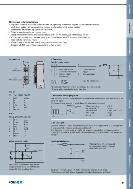
In<strong>for</strong>mationStructure <strong>and</strong> per<strong>for</strong>mance features– 1-quadrant controller. Positive set value alterations are adjusted by acceleration. Negative set value alterations causeshort-circuit braking via the motor winding (increase in intermediate circuit voltage possible!)– Speed setting via set value input (interface 0 to10 V <strong>DC</strong>)– Setting of operating modes via 2 control inputs– Speed-controlled version with evaluation of Hall signals <strong>for</strong> <strong>AC</strong>TUAL speed value monitoring via MF-pin– With voltage-controlled (= uncontrolled) version, no braking function <strong>and</strong> <strong>AC</strong>TUAL speed value monitoring– Fixed limits <strong>for</strong> current <strong>and</strong> voltage– Voltage supply with input filter, filtering <strong>and</strong> generation of auxiliary voltage– Equipped with PCB plug or Molex plug depending on type of motorVARIODRIVEVARIODRIVE CompactPin connectionPlug S2MolexS23 62 5Control signals1 4S1Motor connection4 83 72 61 51618AMP1. Control inputSpeed-controlled versionAB0 0 Output stage disabled0 1 Counter-clockwise rotation1 0 Clockwise rotation1 1 Brake function*low (0)high (1)0 to 0,8 V2,4 to 30 V*Brake function: The braking function serves to slow down the motor only.It has no holding brake function <strong>for</strong> the static duty.A0 Counter-clockwiserotation1 Clockwise rotationInput B is not connectedA/BGNDECI motorVario<strong>Drive</strong> CPin Type MOLEX Type AMP1 GND MF-Pin2 A B3 S+ A4 +UB S+5 B Gnd6 MF-Pin +UBPlug S1Pin Type MOLEX Type AMP2. Actual speed value output (MF-Pin)Only with speed-controlled version, open collector that transmits a short pulse at every edge change of themotor Hall signals.The illustrated signal sequence <strong>for</strong> st<strong>and</strong>ard assembly is the speed value output.150ustGNDMF-PinVoltage range U CE :Max. current I c :Pull-up resistor:Pulse length:U CESat :< 30 V10 mA> 2000 Ohm at 24 V150 μs< 0,8 VBG motor1 L 3 +UHall2 +UHall GndHall3 RLG 2 RLG 34 RLG 1 RLG 25 L 2 RLG 16 L 1 L 37 GndHall L28 RLG 3 L 13. Set value inputThe speed selection is normally made externally with a voltage in the range of 0 to10 V <strong>DC</strong>. A voltage of 10V is equivalent to the maximum speed determined internally.With the voltage controlled version of the VT-A, the set value is internally fixed at the maximum value.To reduce the set value, an external potentiometer can be connected or an external set value voltage canbe applied.BCI motorVoltage-controlled versionS+GND2k2GND12 V12 V10k22nFInt. Comm<strong>and</strong>Typical wiring of the reference input with thevoltage controlled version. Special features arecontained in the relevant data sheets.Speed-controlled versionS+S-The interpretation of the set value <strong>and</strong>the corresponding level are describedin the relevant data sheet.For detailed in<strong>for</strong>mation, please refer to the corresponding specification data sheets.The instructions <strong>and</strong> safety notes in the operating manual must be observed at all times.GND21Representatives Specifications <strong>AC</strong> motors