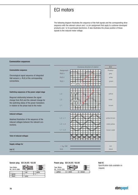
ECI motorsThe following diagram illustrates the sequence of the Hall signals <strong>and</strong> the corresponding drivesequence with the relevant colours <strong>and</strong> / or pin assignment that apply to customer-developedproducts <strong>and</strong> / or to purchased electronics. It also illustrates the phase position of thesesignals to the induced motor voltage.Commutation sequencesClockwise direction of rotationECICommutation sequenceAssignmentPositionChronological signal sequence of integratedHall sensors (= RLG) at the correspondingconnections.RLG 3RLG 2RLG 1360°electricalgreywhitegreenSwitching sequences of the power output stageL3Phase WyellowRequired relationship between the signalchange from RLG <strong>and</strong> the relevant change <strong>for</strong>the switching status of the power transistorsin relation to the phase lead to the motor.L2L1Phase VPhase UvioletbrownInduced voltagesIdealised illustration of the sequence of theinduced voltages between the relevant connections.L3-L1L2-L3yellow-brownviolet-yellowL1-L2brown-violetTotal of induced voltagesSupply voltage <strong>for</strong>Hall IC+ U , Hall BGndredblackSensor plug ECI 24.XX / 63.XX Power plug ECI 24.XX / 63.XX Hall ICType: MolexNo.: 39-01-2085greenblackredgreywhiteType: MolexNo.: 19-09-10361: yellow 2: violet 3: brown321Specification data available onrequest.78
Nominal dataTypeECI motorECI 30.20Nominal voltage (U BN ) V <strong>DC</strong> 24– Very dynamic 3-phase, 6-pulse internal rotor motor.– EC <strong>technology</strong> with slotless stator design.– Extremely silent running, no cogging torque.– Very suitable <strong>for</strong> high speed applications due to minimized iron losses.– Dynamically balanced rotor with 4-pole neodymium magnet.– Detection of rotor position via 3 Hall sensors.Option: motor without sensors <strong>for</strong> sensorless operation.– Precision ball bearings <strong>for</strong> long service life <strong>and</strong> silent running.– Motor supply <strong>and</strong> control via external operating electronics.Nominal speed (n N ) rpm 30 000Nominal torque (M N ) mNm 10Nominal current (I BN ) A 1,9Nominal output power (P N ) W 32Speed at no-load operation (n L ) rpm 43 000No-load current (I BL ) A 0,20Continuous stall torque (M BNO ) mNm ---Permissible eff. continuous stall current, motor lead (I nOeff ) A ---Permissible continuous stall power (P BnO ) W ---Short-term permiss. peak torque (M max ) mNm 45Permiss. peak current, motor lead (I max ) A 8Induced voltage (U imax ) V/1000 rpm 0,62Terminal resistance (R v ) Ω 1,9Terminal inductance (L v ) mH 0,26Rotor moment of inertia (J R ) kgm 2 x10 -6 1,5Thermal resistance (R th ) K/W ---Protection class IP 20ECI 30.20 B01Ambient temperature range (T U ) °C 0 to +40Motor mass (m) kg 0,21Order No. 932 3020 001[min -1 ][x1000]F radialLF axialF axial 6NF radial 1N L 1 10 mmPermissible shaft load at nominal speed <strong>and</strong> lifeexpectancy L 10 at 20 000 h (at T U max. 40°C).40 4,0M30 3,020 2,010 1,02I4 6 8 10[mNm][A]0Operating electronics:DRIVECONTROL VT-A in aversion without speed controlcan be used <strong>for</strong> tests(adapter cable necessary).0,0816o3,9 r610240Blind holes <strong>for</strong> self threading screwsaccording to DIN 7500. Screw indepth 5,3 mm max.9 0,3 38,8 0,3 4,2 0,2(3x) 2,3 H101,7 0,20,114o35 0,145 0,1o263x 120°79Representatives Specifications <strong>AC</strong> motorsBCI motorBG motorECI motorVario<strong>Drive</strong> C VARIODRIVE Compact VARIODRIVE In<strong>for</strong>mation